Week 2 - Flow over a Cylinder.
AIM
-
Simulate the flow over a cylinder and explain the phenomenon of Karman vortex street.
PART-I
- Simulate the flow with the steady and unsteady case and calculate the Strouhal Number for Re= 100.
PART-II
- Calculate the coefficient of drag and lift over a cylinder by setting the Reynolds number to 10,100,1000,10000 & 100000. (Run with steady solver)
- Discuss the effect of Reynolds number on the coefficient of drag. [ Results should be validated with any standard literature and error should be within 5 %]
INTRODUCTION
- One of the fundamental simulations in the CFD domain involves flow over a cylinder. Even now, extensive research is being done to comprehend the cylinder wake flow's complex unstable dynamics. Beyond a critical Reynolds number, experimental measurements and numerical calculations have both supported the onset of instability of the wake flow behind a cylinder, eventually leading to a type of periodic flow identified by distinct frequencies, popularly known as the Von Karman vortex street. Laminar flow past cylinders with regular polygonal cross sections typically separates at one or more sharp corners of the geometry of the cross section itself, leaving a system of vortices on either side of the mid symmetry plane.
- The physics of the flow are far more complicated than what its deceptively basic shape may suggest for a circular cylinder, where the point of flow separation is determined by the characteristics of the upstream boundary layer.
THEORY
- The Reynolds number, which is the ratio of inertial to viscous forces, controls the transition from a laminar to a turbulent region.
-
`Re=(rho.V.D)/mu=(V.D)/nu`
where `rho`=Density of flowing fluid
V= Free stream velocity
D=charectristic dimension of body
`mu`=dynamic viscosity of fluid, `(N-s)/m^2`
`nu`=Kinematic viscosity of fluid, `m^2/s`
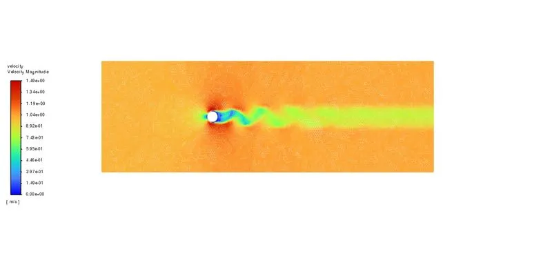
- Vonkarman vortex street is a repeating pattern of swirling vortices caused by a process known as Vortex shedding which is responsible for the unsteady separation of flow or fluid around blunt bodies.
- vortex shedding is an oscillating flow that takes place when a fluid such as air or water flows past a bluff (as opposed to streamlined) body at certain velocities, depending on the size and shape of the body. In this flow, vortices are created at the back of the body and detach periodically from either side of the body forming a von Karman street. The fluid flow past the object creates alternating low-pressure vortices on the downstream side of the object. The object will tend to move toward the low-pressure zone.
- If the bluff structure is not mounted rigidly and the frequency of vortex shedding matches the resonance frequency of the structure, then the structure can begin to resonate, vibrating with harmonic oscilations driven by the energy of the flow. This vibration is the cause for overhead power line wires humming in the wind, and for the fluttering of automobile whip radio antennas at some speeds.
-
The frequency at which vortex shedding takes place for an infinite cylinder is related to the Strouhal number by the following equation:
Where
 is the dimensionless Strouhal number,
  is the vortex shedding frequency (s-1),
  is the diameter of the cylinder (m), and
  is the flow velocity (m s-1).
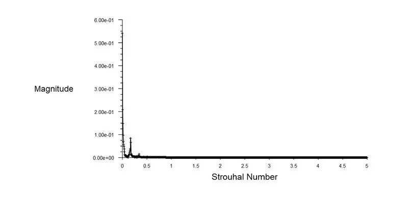
 - For Reynolds number, from 100 to 100000, the Strouhal number varies only between 0.18 and 0.22.
- Co-efficient of drag: it is a dimensionless quantity used to quantify the drag or resistance of an object in a fluid environment like air or water. lower drag coefficient indicates the object will have less aerodynamics drag.
-
The drag coefficient
 is defined as
where:
 is the drag force, which is by definition the force component in the direction of the flow velocity.
 is the mass density of the fluid.
 is the flow speed of the object relative to the fluid.
 is the reference area.
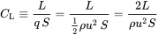
- Co-efficient of lift: it is a dimensionless coefficient that relates the lift generated by a lifting body, to the fluid density around the body, the fluid velocity and an associated reference area.
-
The lift coefficient CL is defined by
 ,
,
where
 is the lift force,
  is the relevant surface area and
  is the fluid dynamic pressure, in turn linked to the fluid density
  , and to the flow speed
  .
. - One of the important factors that could lead to the investigation of vortex shedding in practical applications like bridges, aircraft control surfaces, heat exchangers, and many others is the vortex-induced vibration. For the design and development of a very good scale product, it is necessary to study the vibration brought on by the vortex phenomena resulting from flow dynamics.

SOLVING AND MODELLING APPROACH
- The project's primary goal is to investigate how Reynolds number affects flow along a cylinder. It is crucial to have a larger flow domain and a smaller mesh size to catch every vortex in the wake zone in order to capture the flow with every regime.
- The 2D geometry of the flow field and mesh will be the first part of problem. For the flow domain to be fully captured, a smaller mesh size is crucial. To capture boundary layer detachment from the cylinder's surface, an inflating layer will be introduced close by.
- Laminar model will be used to solve the simulations since the Reynolds number used falls under the laminar flow.
- For steady state and unsteady state solver SIMPLE interpolation scheme will be used to calculate results.
- User defined material will be used as the flow fluid.
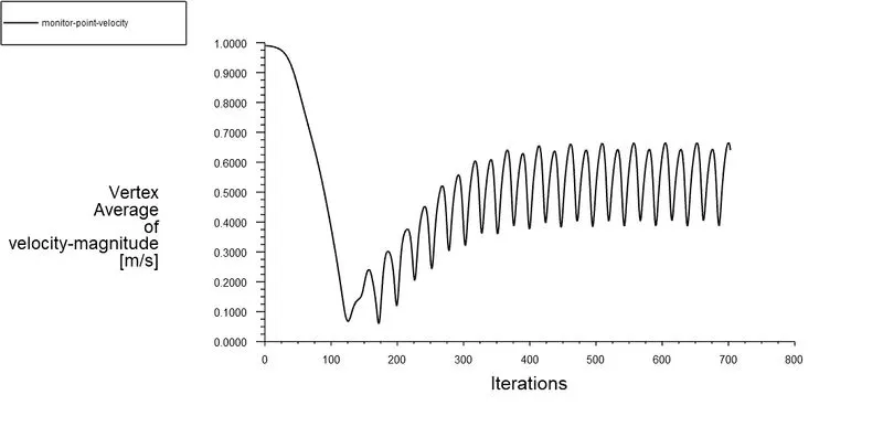
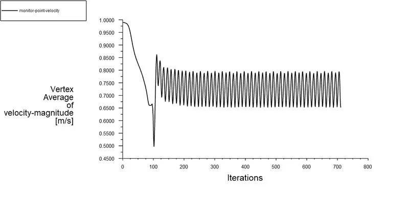
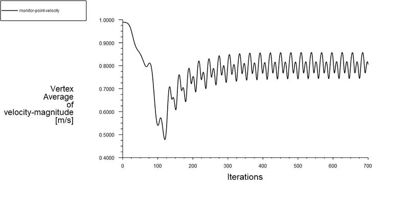
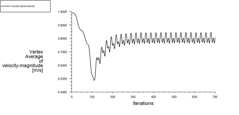
- Create a monitor point at a distance of 2D from behind the cylinder to plot the vertex average velocity. This plot helps to find the Strouhal number.
- Later plot and calculate the coefficient of lift and coefficient of drag.
PRE-PROCESSING AND SOLVER SETTINGS
- Geometry
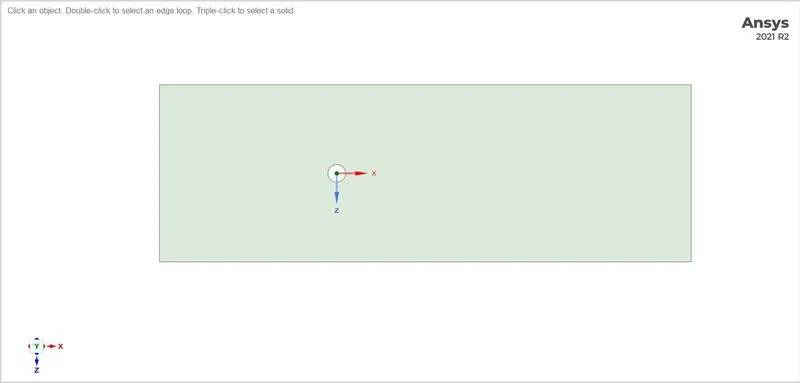
- Create a 2-D model in spaceclaim as shown in figure below. The dimensions are:
- Diameter of the circle = 2m
- Length of the domain to left of the origin of the circle = 20D
- Length of the domain to right of the origin of the circle = 10D
- Height of the domain = 10D
- After creating the geometry, load the geometry to the mesh part.
- Meshing
- Open the meshing window. Mark inlet, outlet, wall and symmetry in the named selection.
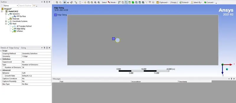
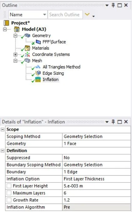
- Mesh the geometry with the element size = 0.25m. Edge sizing is needed to apply to the cylinder as shown in th figure below.
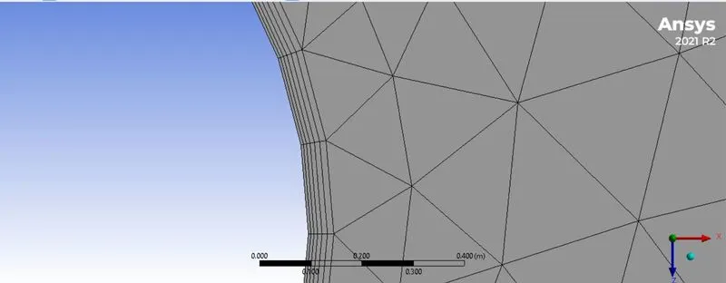
- It is important to capture the flow near cylinder, hence the inflation layer is need to be used as shown in the figure below.
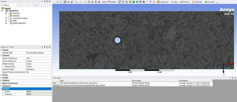
- Mesh model is shown in the figure below for element size = 0.25m.
Solver requirements
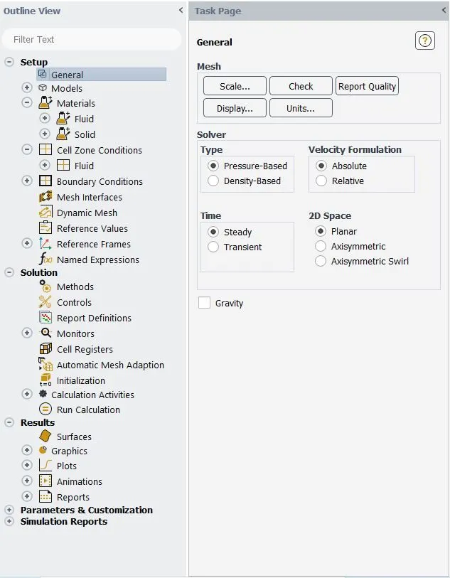
- General setup used in solver is shown in the figure below.
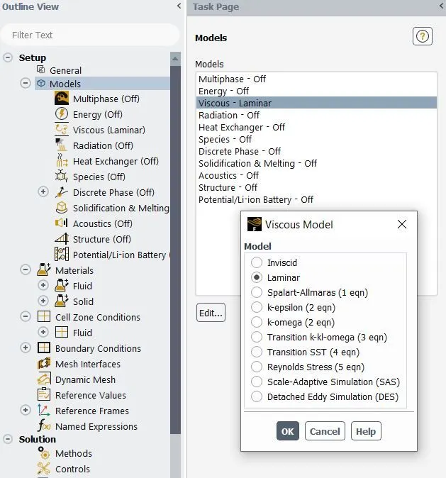
- Use viscous model as Laminar as hsown in the figure below since Re used are 10, 100, 1000. Use Turbulence model k-omega SST for Re = 10000 and 100000.
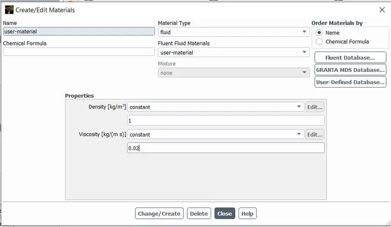
- Use the user defined fluid material instead of default material i.e., air as shown in the figure below. User defined material has density of 1 kg/m^3 and viscosity of 0.02 kg/ms.
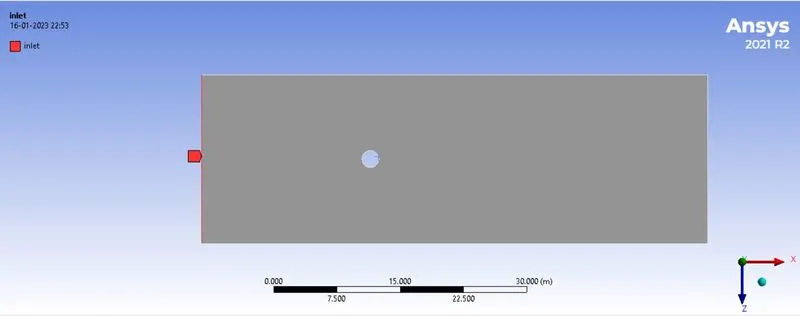
- Next asign the boundary conditions for the fluid model as shown in the figures below.
- Inlet - inlet velocity = 1m/s.
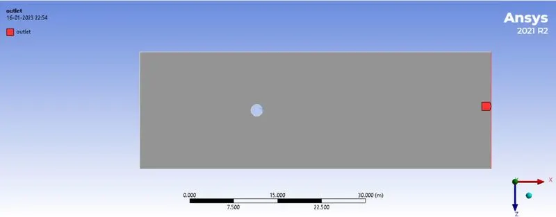
- outlet - pressure outlet
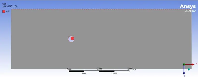
- wall
- Symmetry
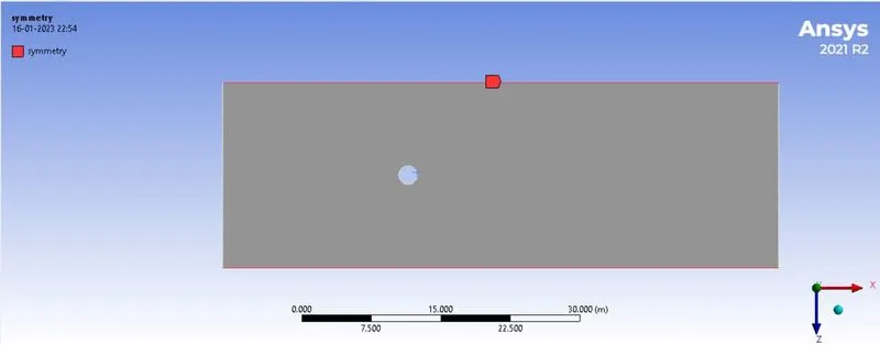
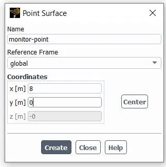
- Insert a monitor point to the left of the cylinder at distance of 4D m as shown in the figure below.
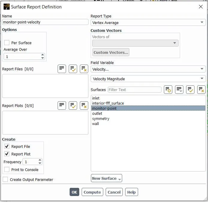
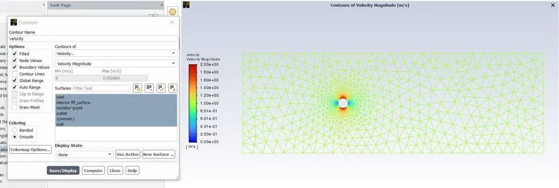
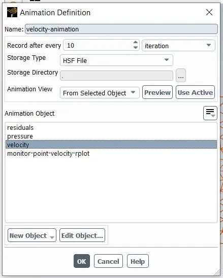
- Create report definition for vertex average of velocity, Coefficient of drag and Coefficient of lift, Contours for velocity and also set velocity contour animations as shown in the figures below.
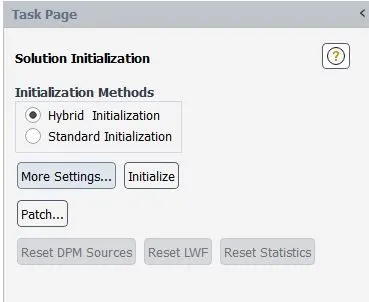
- Initialize the model for Hybrid initialization.
RESULTS
Part 1 : Flow with the steady and unsteady case and calculation for the Strouhal Number for Re= 100.
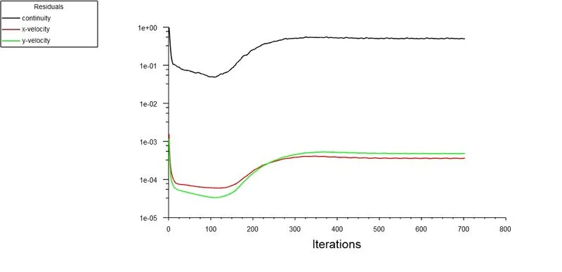
- Steady case Re = 100
- Residual plot
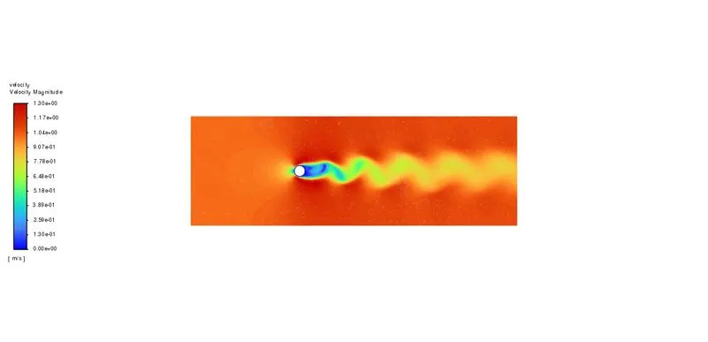
- Velocity contour
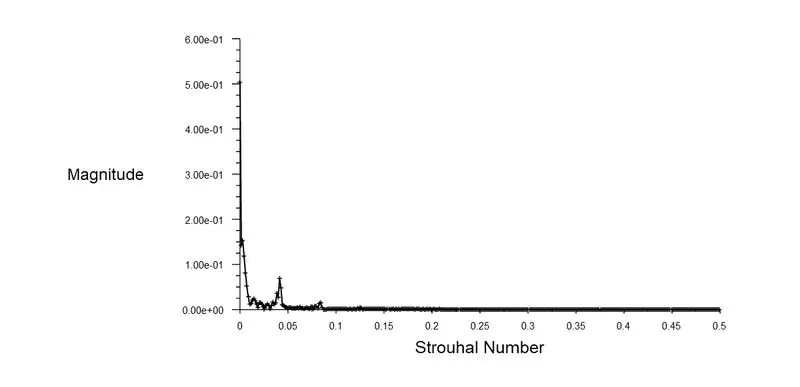
- Strouhal Number
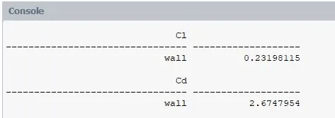
- Coefficient of Drag and Lift
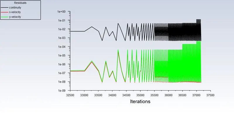
- Unsteady case Re = 100
- Residual plot
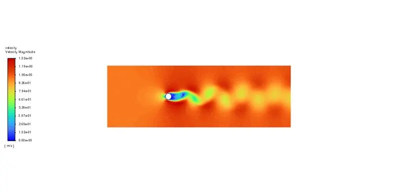
- Velocity contour
- Strouhal Number
- Coefficient of Lift and Drag
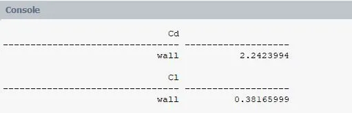
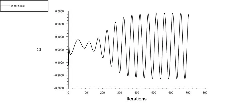
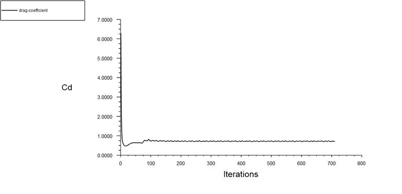
- The below table shows the Coefficients of Drag and Lift for both steady and unsteady case at Re = 100.
-
Solver Coefficient of Drag Coefficient of Lift Steady state 2.674 0.231 Unsteady state 2.24 0.381
- When we compare both the cases, we can say that the flow has converged when the the flow reaches from inlet to outlet and we obtain the required vortex shedding or von Karman vortex street effect. hence we can look into the velocity contour plots to understand whether the flow is converged or not.
- The value of Coefficient of Lift validates to the value in the Simulation of cross flow induced vibrations by Eric Williams.
- Part 2 : coefficient of drag and lift over a cylinder by setting the Reynolds number to 10,100,1000,10000 & 100000.
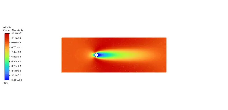
- Re = 10
- Velocity contour
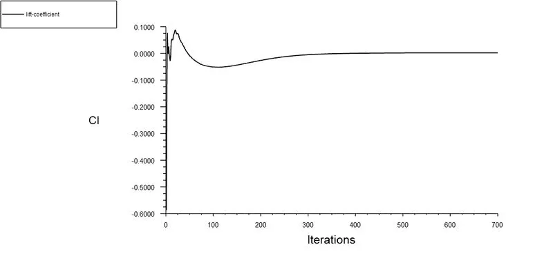
- Coefficient of Lift
- Coefficient of Drag
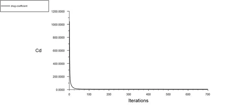
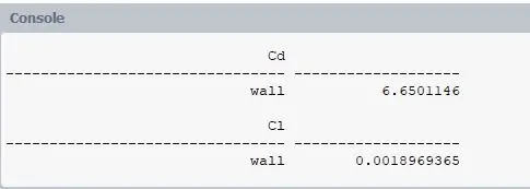
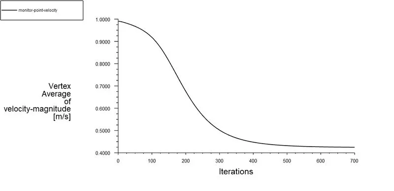
- Vertex average velocity at monitor point
- Re = 100
- Velocity contour
- Coefficient of Drag
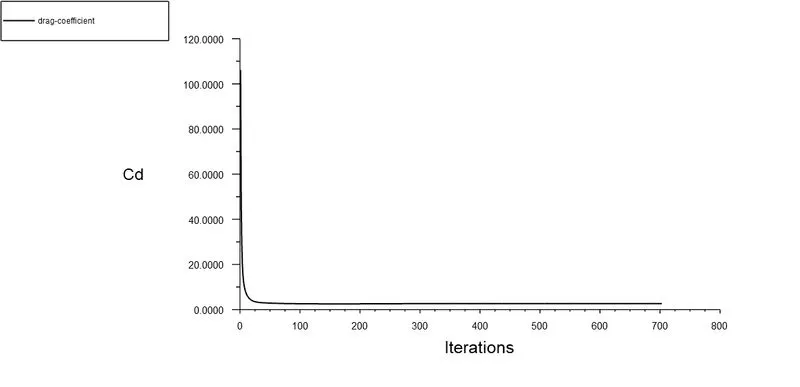
- Coefficient of Lift
- Vertex average velocity at monitor point
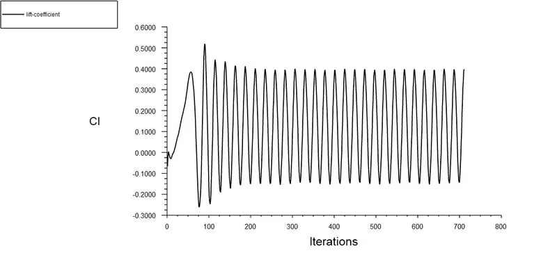
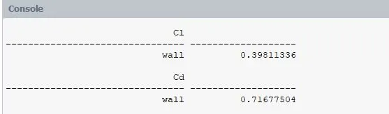
- Re = 1000
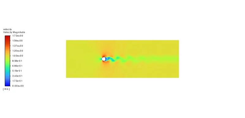
- Velocity contour
- Coefficient of Drag
- Coefficient of Lift
- Vertex average velocity at monitor point
- Re = 10000
- Velocity contour
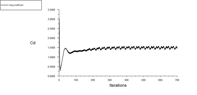
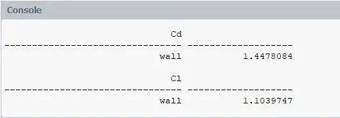
- Coefficient of Drag
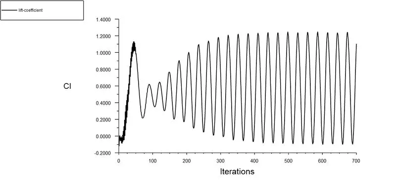
- Coefficient of Lift
- Vertex average velocity at monitor point
- Re = 100000
- Velocity contour
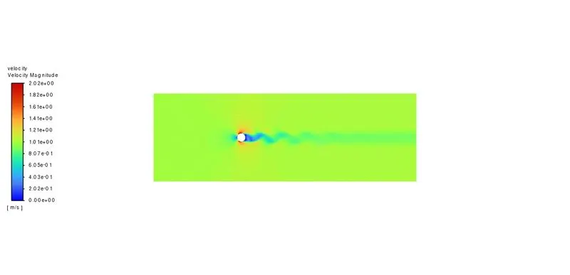
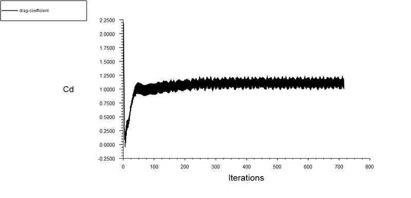
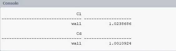
- Coefficient of Drag
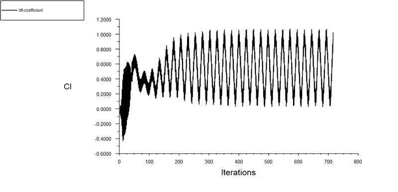
- Coefficient of Lift
- Vertex average velocity at monitor point
- The below table shows the Coefficients of Drag and Lift for Reynolds Number 10, 100, 1000, 10000, 100000.
-
Reynolds Number Coefficient of Drag Coefficient of Lift 10 6.650 0.00189 100 2.674 0.231 1000 0.716 0.398 10000 1.44 1.103 100000 1.001 1.223
CONCLUSION
- As we can conclude from the table that, as the Reynolds Number increases the coefficient of Drag gets decreased and also due to the increased Reynolds Number the Coefficient of Lift gets increased.
- This phenomena occurs because when the Reynolds number increases, the surface friction between the fluid and the cylinder also rises, causing the boundary layer to rupture before the flow separates and resulting in a decrease in drag and an increase in lift.
- As the Reynolds Number increases the effect of vortex shedding gets increased to the right of the cylinder body.