Week 2 - Flow over a Cylinder.
Aim:
To simulate the flow over a cyinder a 2d simulation in both steady and un steady case.
Objective :
1) To calculate the co efficient of lift and co efficient of drag by varying the Reynolds number settings as 10, 100, 1000, 10000 etc in a steady state solver.
2) Discuss the effect of reynolds number on cofficient of drag.
Theory :
Karmon vortex is the repetting swirling of the fluid flow that happens after certain period of the flow in the shedding. This flow can also be taken as convergence pattern.
The proper search is circular motion of the fluid flow along the centre line.
Procedure:
To Evaluate the given conditions, initially we need to set a boundary for the cylinder model and based on that solution is estimated and evaluated.
Steps in ansys fluent for the flow over the cylinder :
step 1) open the ansys fluent and space claim to create a 2D cylinder pattern.
Draw initially the circle with diameter of 2m and make a rectangle with 60*20 m .
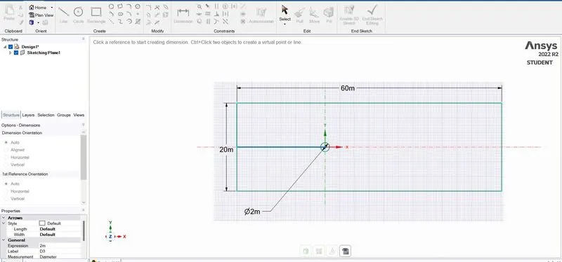
2) convert this into 3d form by pressing the pull window or return to 3d mode.
close the geometry and proceed for meshing.
3) Right click the mesh and edit, the geometry which is created will directly imported in this meshing area. Only the setup changes to be done.
Initial generation of mesh be quadrilateral it should be converted into tria for this simulation.
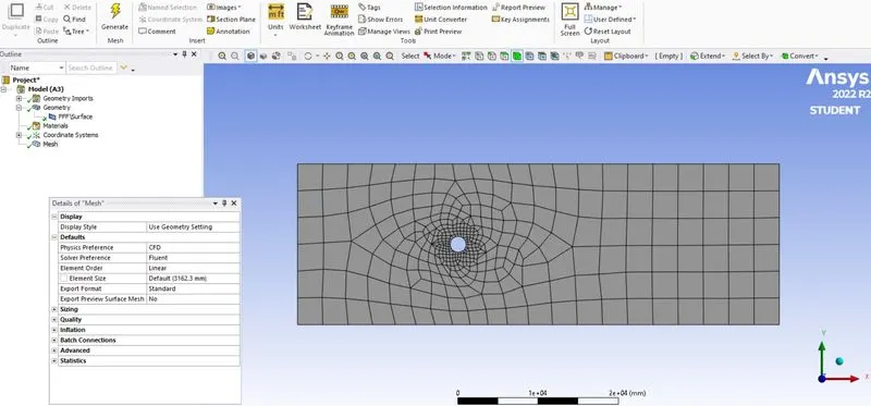
To change right click mesh ---> insert ---> method---> select the geometry ---> apply ---> change from quadrilateral to tria ---> generate mesh (which gives the tria mesh).
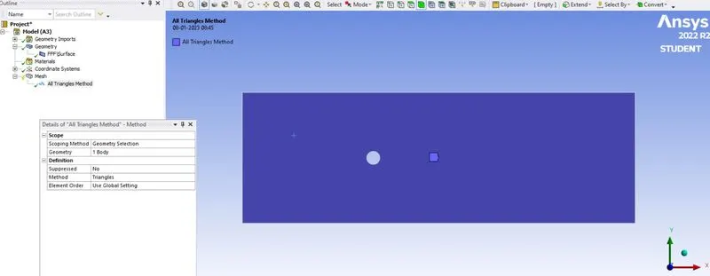
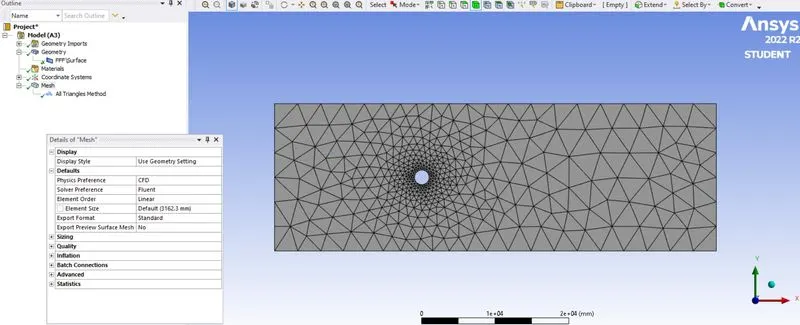
Since the element size is too large change that into 500 mm make it refining.
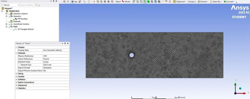
4) The edge of the cylinder is uneven which the flow can be affected. Since the flow crosses the edge it has to captured in very finer ways so that the nature of the flow velocity can be defined with minimum error and maximum accuracy.
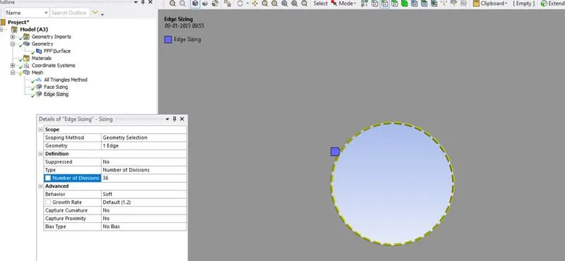
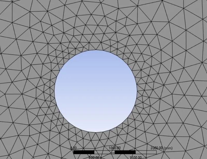
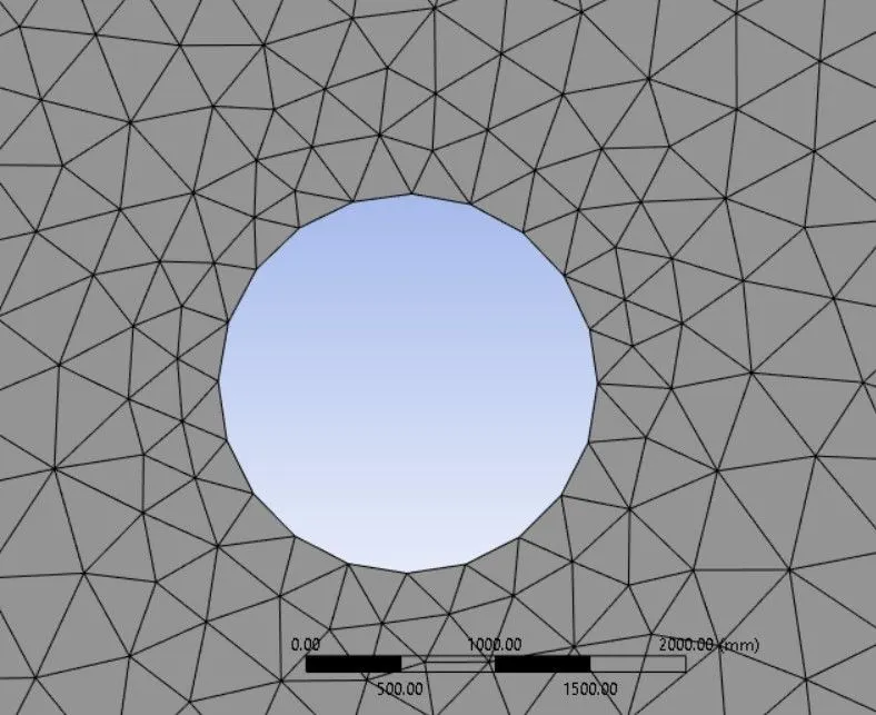 Right click mesh ---> sizing ---> select edge and edge of the circle ---> apply ---> number of division ---> 36 ( 360 deg of circle with 10 deg inclination for each edge ). ---> generrate mesh.
 ----->
5) Inflation layer is formed to create a structured mesh at the boundary layer which capture the flow very closely towards the boundary.
Mesh ---> inflation layer ---> boundary selection ---> frist layer thickness of height 5 mm ---> 6 layer formed.
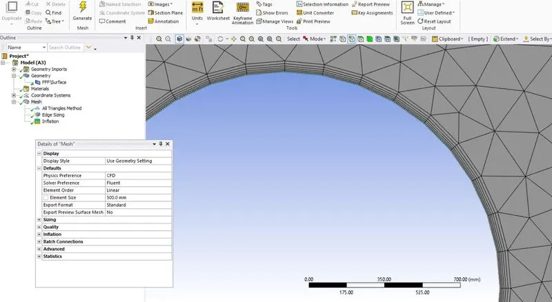
Naming has been given.
6) Setup right click edit.
Setup is the area where all the physical parameters for the simulation is done.
Pressure based solver ---> steady state ---> viscosity as (laminar)
material selection ---> fluent data base ---> air ---> copy ---> new name as air new ---> change /create ---> cell zones ---> select the available surface ---> edit ---> material as air new which is created already ---> again material ---> detele the available air ---> and fro the created air new material select the density as 1 kg /m^3 and viscosity is 0.05 kg /ms.
set boundaries condition for inlet --> outlet --> wall.
To track the velocity flow monitor point is needed.
Results ---> create ---> 8m from x axis and point is created .
solutions ---> method ----> simple .
defnition ---> new ---> surface report ---> vertex average ---> in the monitor point ----> velocity ---> print to console.
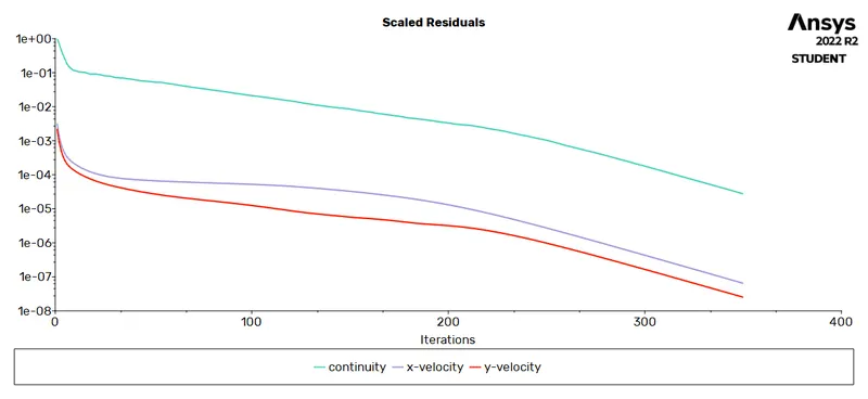
solutions ---> residuals ---> print to console ---> ok
To lift and drag report ---> defnitions ---> force report ---> lift select and boundary ----> create the lift report.
to drag ---> definitions ---> force report ---> drag select and boundary ---> create the drag report.
7) Initiallize the simulations for the given conditions .
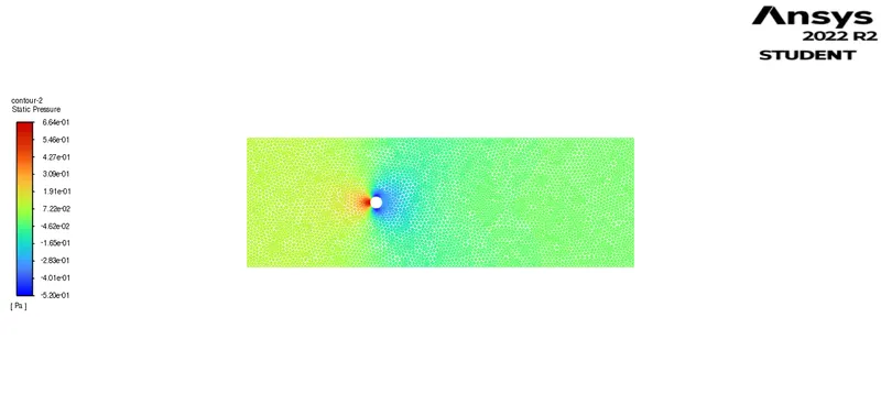
After initializing ---> create the animations ---> for the velocity and pressure contour.
press calculate for the iteration of 350 .
The obtained results :
velocity contour
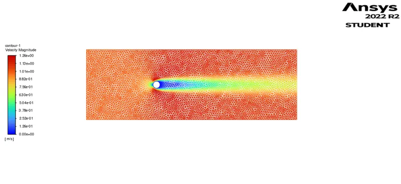
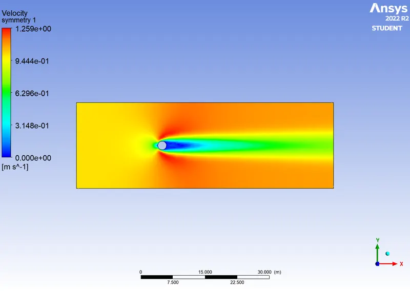
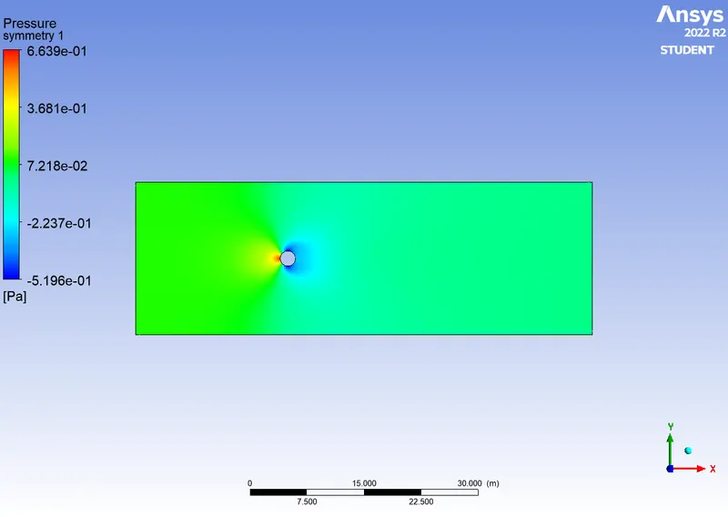
pressure contour:
residuals :
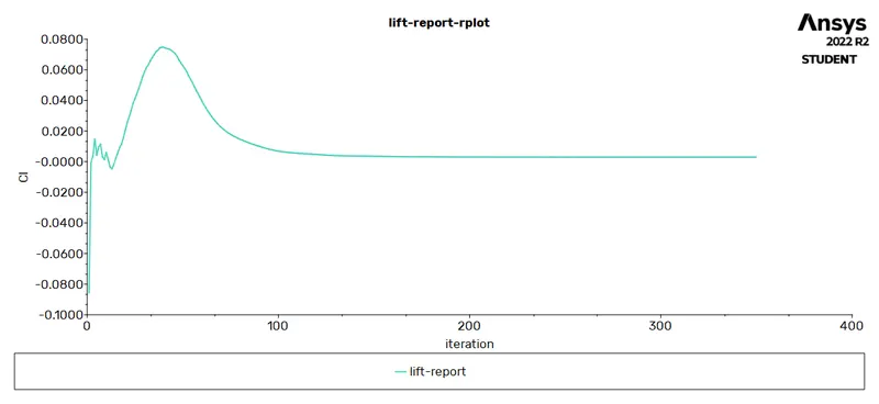
lift report :
Drag report;
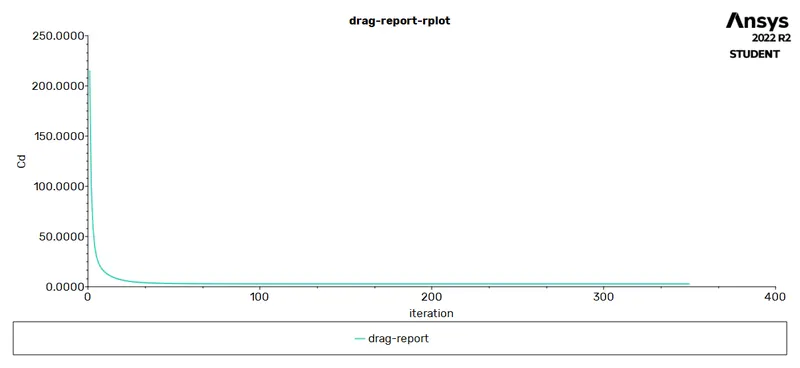
THE CONVERGENCE OF LIFT AND DRAG IS :
cl (lift co efficient ) = 0.0029
cd (drag co efficient ) =2.840
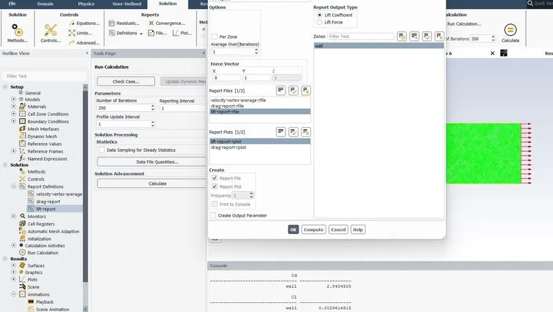
The above mentioned graphs and plots are made for the condition of
viscosity 0.05 kg/ms
velocity 1 m/s
density is 1 kg/m^3
diameter 2m
which gives the reynolds number as
RE = (ρvd)/μ
RE= 40.
With the change as per the request.
AT STEADY STATE :
Reynolds number 10 , 100, 1000 is achieved by attaining a viscosity of 0.2, 0.02, 0.002 respectively.
Based on the changing conditions of setup the following results are obtained.
velocity contour of the moving point is :
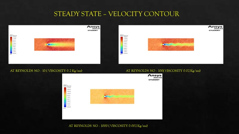
- It is stating that steady state the vorman kortex is achieved by increasing the reynolds number.
- The more finer the mesh the calculation time extends to meet its korman vortex.
Residual of the point :
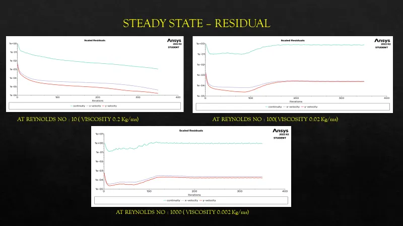
- It is stating that value decrearse initially and reaching the convergence gradually @ reynolds number 10.
- The residual value drops initially and attaing the convergence by increasing@ reynolds number 100
- In third case the value drops steaply and maximum increase is showing at the level near 100 th iteration @ reynolds number 1000
Lift of the cylinder :
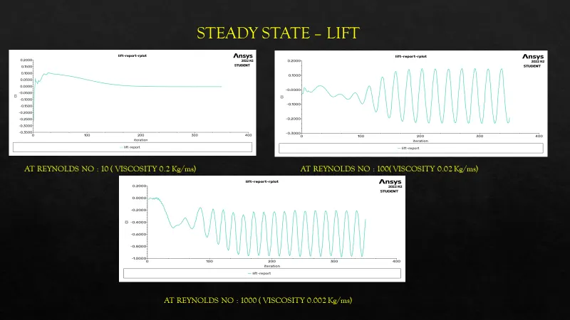
- Lift graph clearly shows the formation of korman vortex at different level of reynolds number.
- Average lift value @ reynolds number 10 is -0.0268
- Average lift value at reynolds number 100 is -0.194
- Average lift value at reynolds number 1000 is -0.354
Drag of the cylinder :
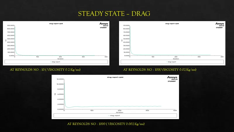
- Average Drag at reynolds number 10 is 5.407
- Average Drag at reynolds number 100 is 2.158
- Average Drag at reynolds number 1000 is 1.181
Velocity average vertex :
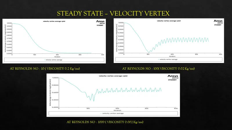
- velocity vertex clearly shows the the convergence status of the monitor point which is at the distance of 5times the diameter.
- The velocity increases when the point is moved away from the wake region of the circle that is towards the outlet wall.
Note the study can be made by increasing the velocity by keeping the viscosity constatnt.
With the change as per the request.
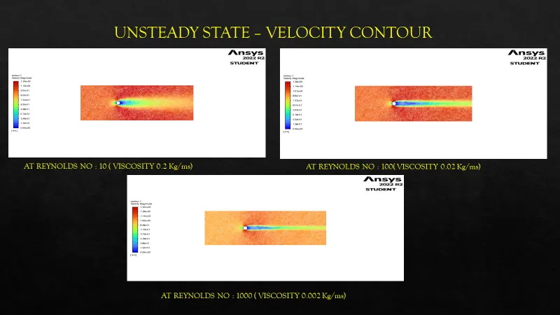
AT UNSTEADY STATE :
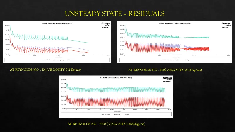
Reynolds number 10 , 100, 1000 is achieved by attaining a viscosity of 0.2, 0.02, 0.002 respectively.
Based on the changing conditions of setup the following results are obtained.
velocity contour of the moving point:
Velocity vertex :
Residuals :
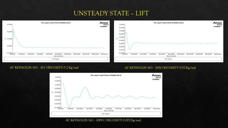
Lift of the point :
- Average lift value at reynolds number 10 is -0.00269
- Average lift value at reynolds number 100 is -0.0479
- Average lift value at reynolds number 1000 is -0.443
Drag of the point :
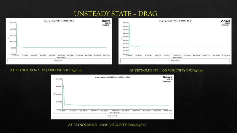
- Average Drag value at reynolds number 10 is 5.40
- Average Drag value at reyolds number 100 is 2.0419
- Average Drag value at reynolds number 1000 is 1.005
Final values are compared with the given research paper and it suits the results .
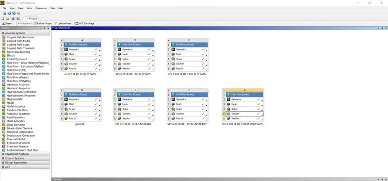
this is the structure of the Flow over cylinder.
Note the study can be made by changing the velocity if the inlet.
Note study can also be done by changing thedistance of the monitor point.
Google link of the project :
https://drive.google.com/file/d/1ogc2_WraeWh07uYaCPXuwZTAoSwh1tjR/view?usp=share_link