Week 2 - Flow over a Cylinder.
Aim
Perform the CFD simulation of user-defined fluid over a 2m dia cylinder with different reynold numbers.
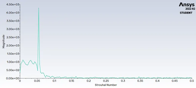
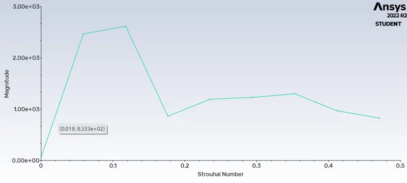
1. calculate the Strouhal Number for Re= 100
2. Calculate the coefficient of drag and lift over a cylinder by setting the Reynolds number to 10,100,1000,10000 & 100000
Introduction
The flow over will show important concepts like:-
1. Vortex Shading
2. Von Karman vortices
3. Strouhal Number
4. Renolds Number
5. coefficient of drag and lift
Theory
1. Vortex Shading
In fluid dynamics, vortex shedding is an oscillating flow that takes place when a fluid such as air or water flows past a bluff (as opposed to streamlined) body at certain velocities, depending on the size and shape of the body. In this flow, vortices are created at the back of the body and detach periodically from either side of the body forming a Kármán vortex street.
2. Von Karman vortices
In fluid dynamics, a Kármán vortex street is a repeating pattern of swirling vortices, caused by a process known as vortex shedding, which is responsible for the unsteady separation of flow of a fluid around blunt bodies.
3. Strouhal Number
In dimensional analysis, the Strouhal number (St, or sometimes Sr to avoid the conflict with the Stanton number) is a dimensionless number describing oscillating flow mechanisms.
4. Renolds Number
In fluid mechanics, the Reynolds number (Re) is a dimensionless quantity that helps predict fluid flow patterns in different situations by measuring the ratio between inertial and viscous forces. At low Reynolds numbers, flows tend to be dominated by laminar (sheet-like) flow, while at high Reynolds numbers flows tend to be turbulent.
5. coefficient of drag and lift
Lift and drag coefficients are proportionality constants that enable the calculation of aerodynamic forces
Solving & Modelling Approach
I have soved through the stages mentioned above with the help of videos shown and guidance of the technical staff.
The process fluesnt fluid flow will be done in following these 5 steps:-
1) Geometry - The geometry of the model will be formed where the actual flow will flow/interfere
2)Mesh - The meshing of the volume is done whoose parameters are set by default with help of 'Boundary Box'
3)Setup - The initial and boundary conditions or parameters and the model choosen are given to the model.
4) Solutions - Based on conditions and requirements the result is calculated with the help of model choosen
5) Results - The final results are appeared here from where the investigation of simulation is done.
Pre-processing and solver setting
Step 0) Change unit to meters
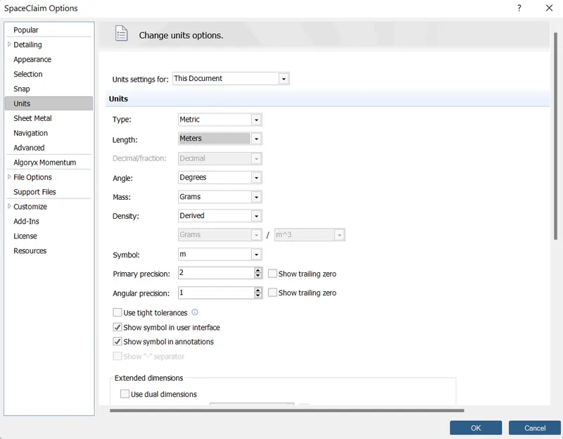
Step 1) The geometry was made .
1.1) 2D sketch was made first according to the conventional dimentions
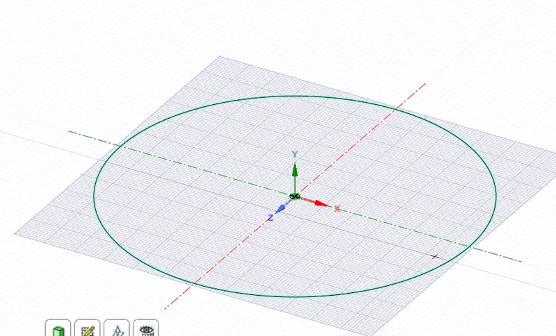
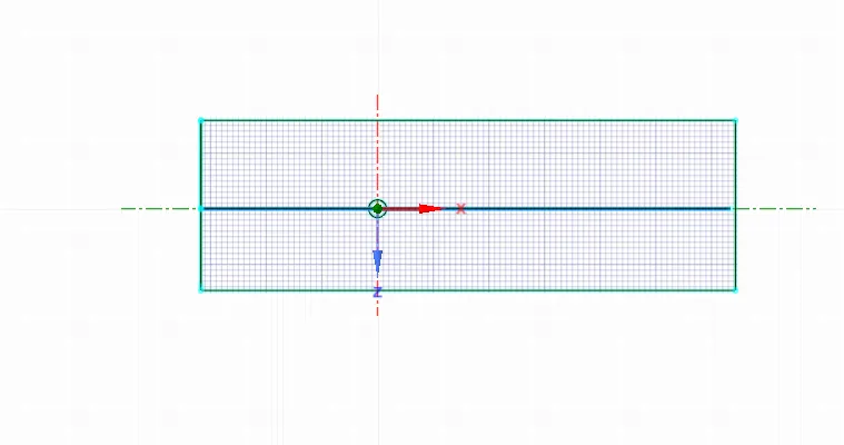
1.2) 2D sketch was converted to 3D using PULL feautre in design.
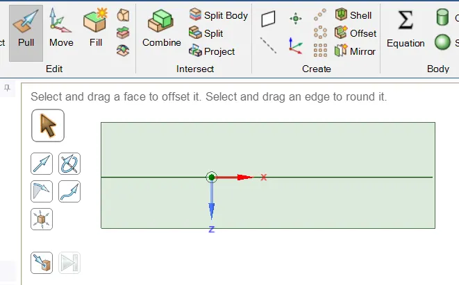
1.3) The sketch features were deleted
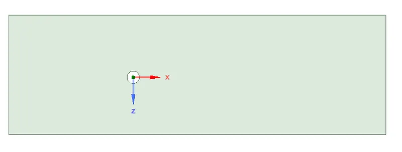
Step 2) Meshing is done
2.1) Mesh element length and shape is given from METHOD
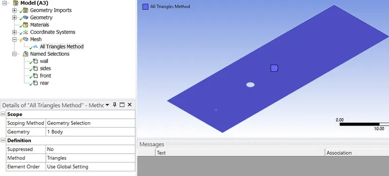
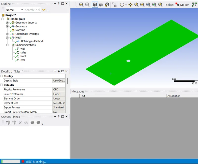
2.2) For fining the cylinder edges SIZING tool is used
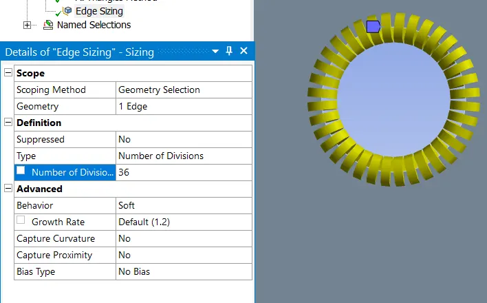
2.3) For better edge foundation, INFILTERATION tool is used.
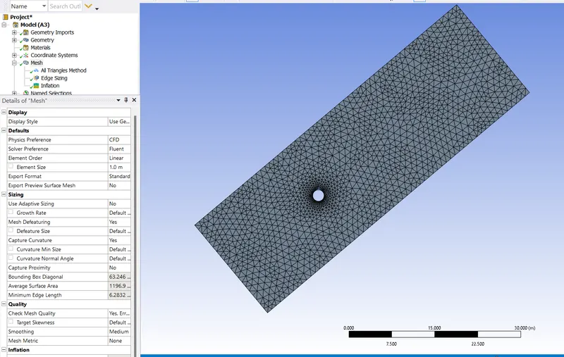
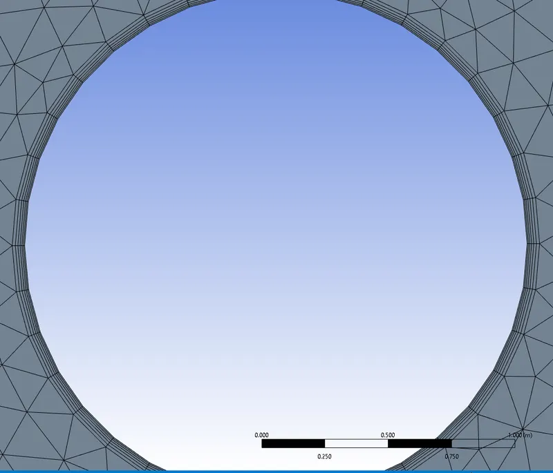
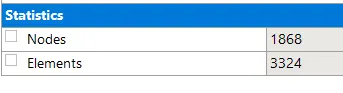
2.4) Assign the names to the edges of the surfaces

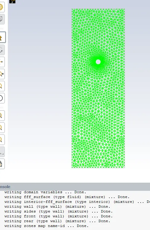
Step 3) Seting-up of model parameters is to be done.
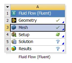
3.0) Check tthe status
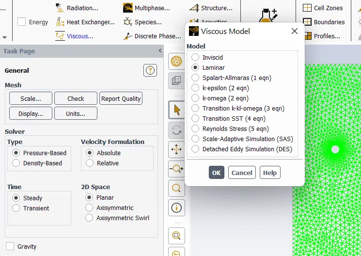
3.1) An user-defined from 'air' is made with new density and viscosity parameters.
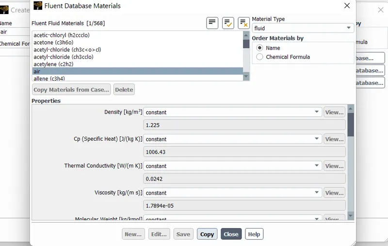
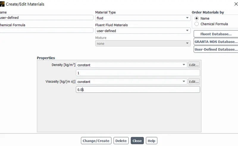
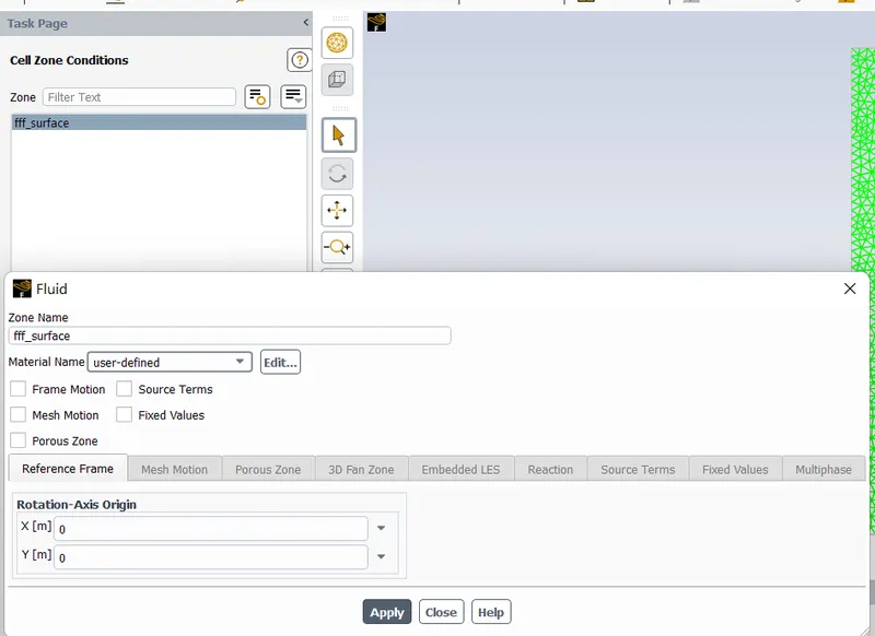
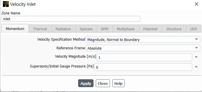
3.2) Boundary Conditions are given, as mentioned below:-
1. Input Velocity Varying with Varying Renolds Number
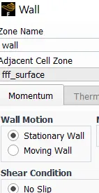
2. No slip to the walls
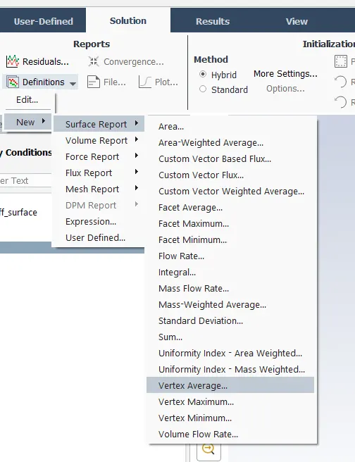
3.3) Define the result parameters to be required
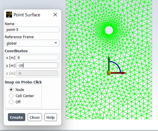
3.4) Creat a point away from cylinder center
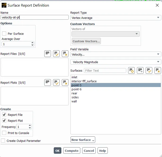
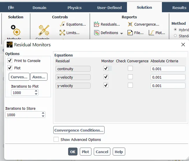
3.4) Un-check the convergence criteria from solving report
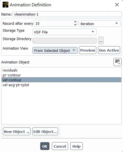
3.5) Give setup for animations
3.6) Give contours from result column
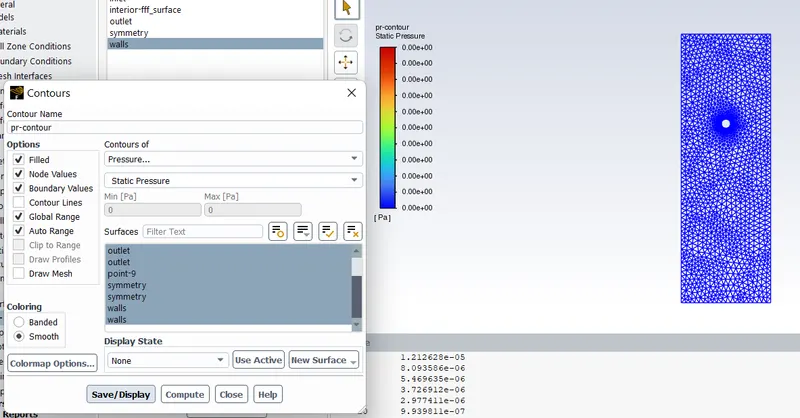
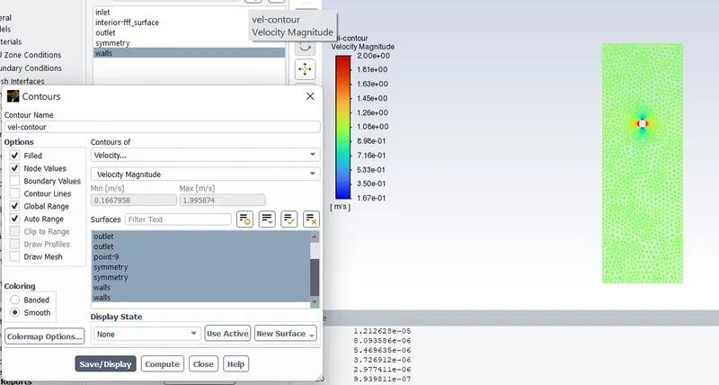
Step 4) Solve the model
4.1) Calculate with 350 iterations and initial conditions
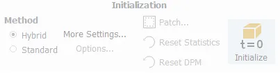
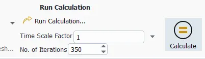
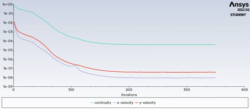
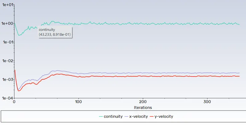
4.2) Compare the convergence graph.
Results
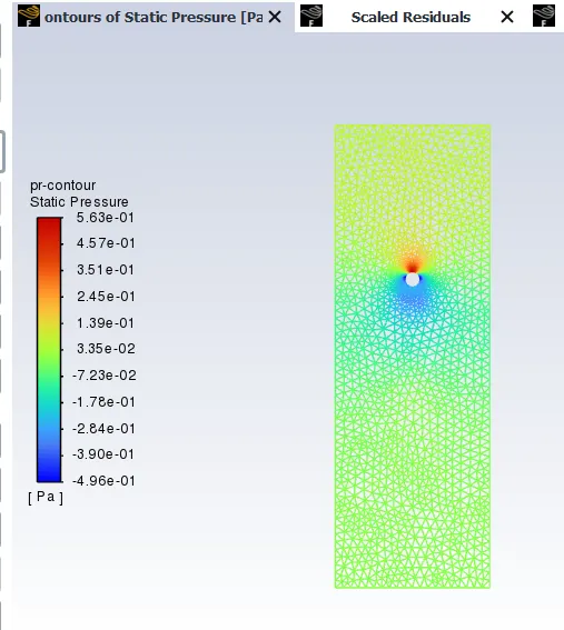
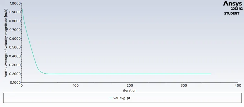
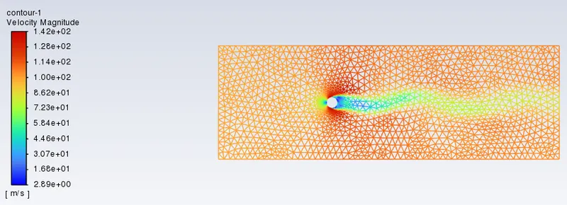
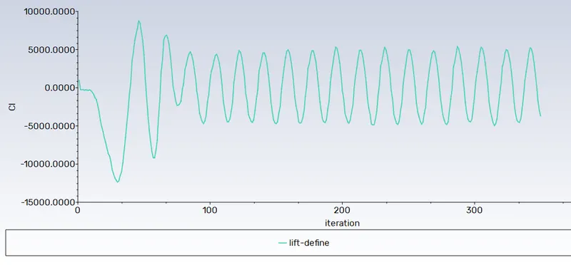
The Velocity contour, Pressure contour, convergence graphs for different Renolds number are given below:-
1. Re = 1

2. Re = 10
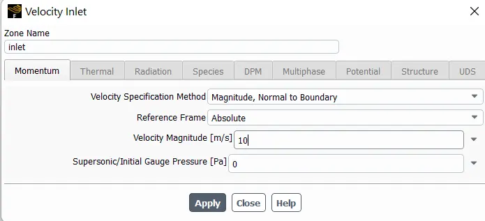
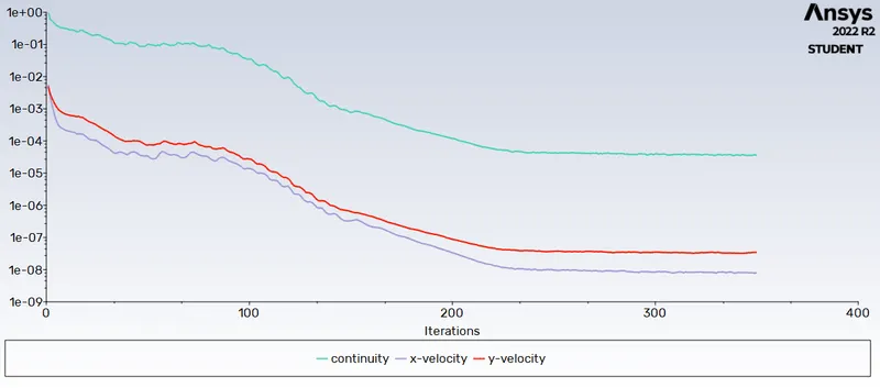
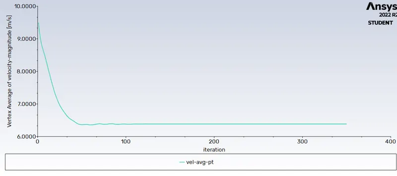
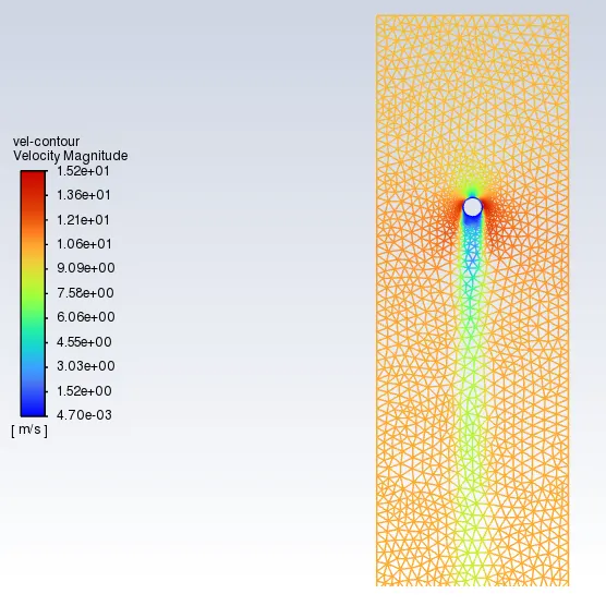
3. Re = 100
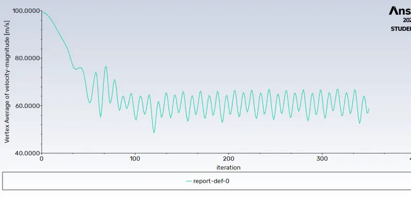
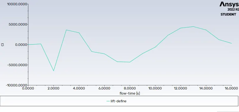
Lift coefficient graph
Strouhal Number graph
| Steady + Re(100) | Un-Steady + Re(100) | |
| Lift coefficient | |
 |
| Strouhal Number graph | |
 |
Conclusion
The following points can be concluded from this report:-
1. Vortex Shedding is more likely to come for finer mesh
2. Shedding comes at higher renolds number
3. High renolds number can be achieved by higher inlet fluid velocity
4. HIgh velocity models take a bit longer time to converge.