Week 2 - Flow over a Cylinder.
AIM- To simulate flow over a cylinder and explain the phenomenon of Karman vortex street and to calculate the strouhal number for both stable and unstable conditions for reynold's number =100. Also, to calculate the drag and lift co- effecients for different values of reynold's number and to study the effects of reynold's number on co-effecient of drag.
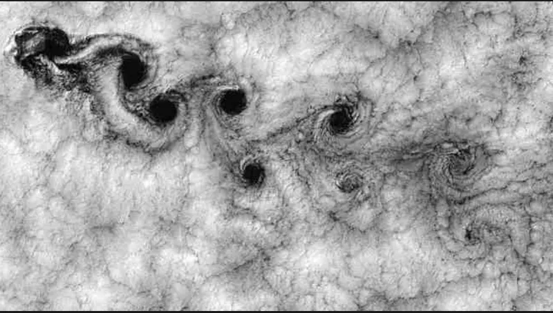
THEORY- Before we proceed any further it is important for us to understand the phenomenon Karman vortex street.Basically, it is a phenomenon that involves a repeating pattern of swirling vortices caused by aprocess called vortex shedding which is responsible for the unsteady separation of flow of a fluid around blunt bodies. A dimensionless number known as strouhal number is used for solving the oscillating unsteady fluid flow problems.It represents the ratio of inertial forces due to local accelaration to the inertial forces due to the changes n velocity from one point to another in the flow field.A vortex street forms only at certain range of flow velocities specified at a certain range of reynold's number, typically above a limiting Re value of about 90.
Von Karman vortex street
The governing eaquation for Reynold's number is as follows,
Re=UL/v
where, U= free stream flow speed
L= characteristic length of the domain
v= kinematic viscosity of the fluid
v=density/dynamic viscosity
In the given case calculations for simulation with different reynold's numbers are as follows,
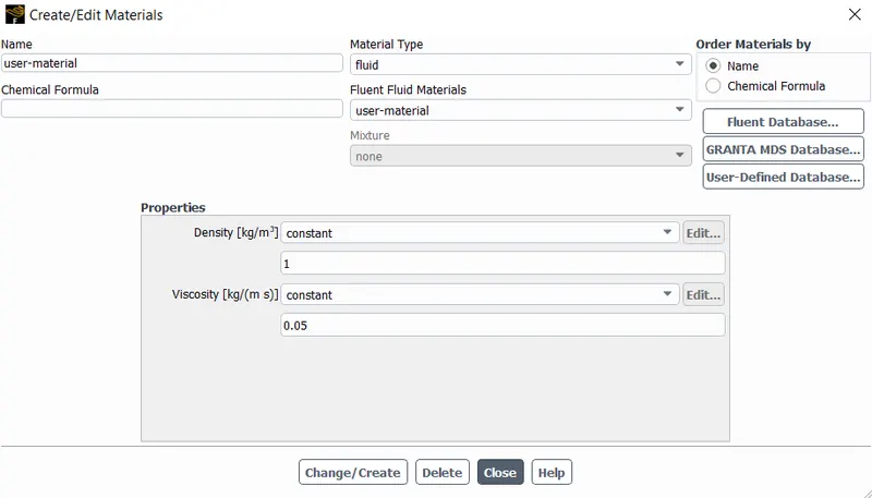
Length of the domain is 2m and density of fluid is specified as 1 kg/m3 and dynamic viscosity is fixed at 0.05 kg/ms ad velocity is calculated and specified at differennt reynold's numbers
For Re=10,
Re=UL/v
10=U*2/0.05
2U=0.5
U=0.25m/s
Similarly,
For Re=100
U=2.5m/s
For Re=1000
U=25m/s
For Re=10000
U=250m/s
For Re=100000
U=2500m/s
Therefore, by varying the above calculated velocities in the boundary conditions strouhal number, co-effecint of drag, co-effecient of lift etc can be computed for respective reynold's numbers
PROCEDURE-
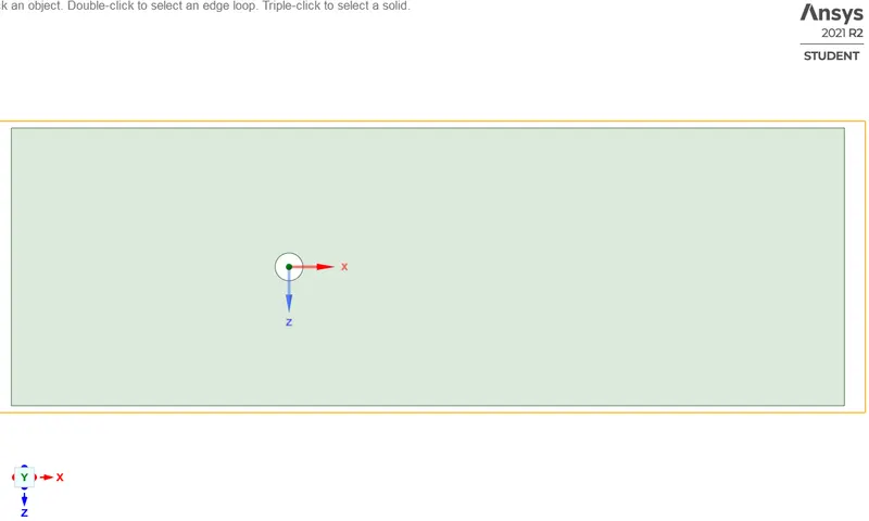
1.The geometry is setup in space claim by constructing a circle of 2m diameter within a rectangle of length 60m and breadth 20m, the circle is positioned 20m from the left side and 40m from the right side, the geometry is then converted into surface by using pull tool the circle is the selected and deleted and also the construction lines are all delelted there by completing the geometry.
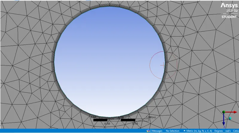
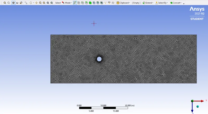
2.The mesh is then generated,initaly a quadrilateral mesh is generated by default which is then changed to triangular mesh,various element sizes are specified and checked for vortex shedding, in this case vortex shedding is observed at 0.5m element size, after the mesh generation the circular edge smoothness is enhanced by using edge sizing tool and 1 division si allocated for every 10 degrees of 360 degrees, hence 36 divisions are allocated for the circular edge and also 6 inflation layers are generated around the circle with offset of 5e-3.
3.The case is then set up by using simple solution scheme.
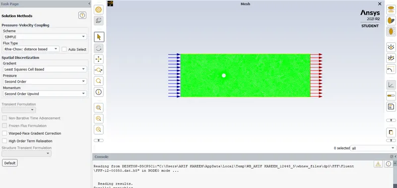
4.The fluid is created as user material and is used for further simulation.
5.In boundary conditions pressure is fixed at 1 atm and viscosity at 0.05 where as velocity is varried for different reynold's numbers.
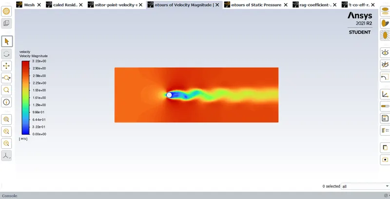
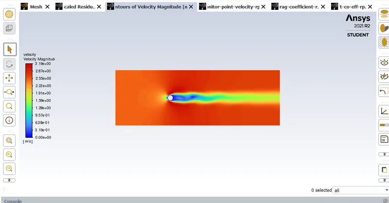
6.Then a monitor point is created to study the velocity of the flow over cylinder and velocity vortex average is plotted and velocity contour is created to visualise the vortex shedding phenomenon and also an animation is created.
7.To calculate co-effecients of drag and lift references are set as follows.
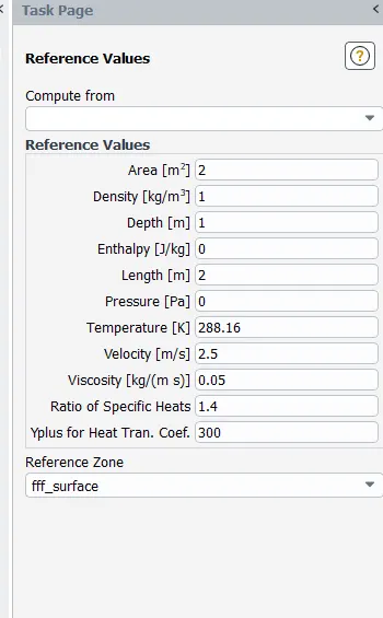
8.Then reprts for drag and lift are generated under definitions.
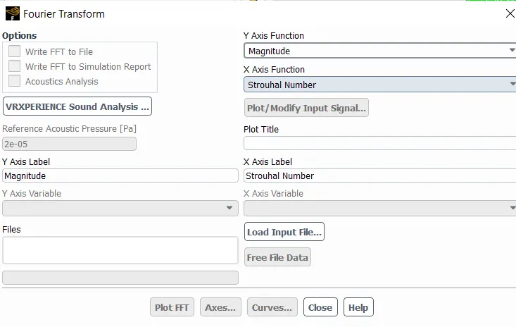
9.The strouhal number is calculated for both steady and transient states by defining a force report for co-effecient of lift at wall.Later, FFT is performed which converts the time dependent value of lift to frequency domain and magnitude is selected on x-axis and strouhal number is selected on y-axis and input file is loaded and then FFT is plotted.
RESULTS-
Part 1-
Velocity contours
Steady state Re=100 Transient state Re=100
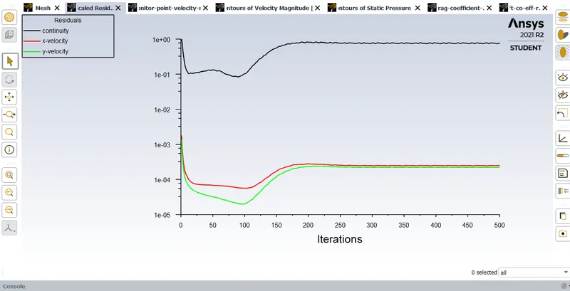
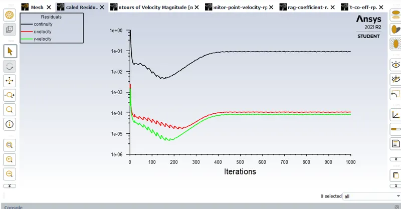
Residual plots
Steady state Re=100 Transient state Re=100
Vertex average of velocity magnitude plot
Steady state Re=100 Transient state Re=100
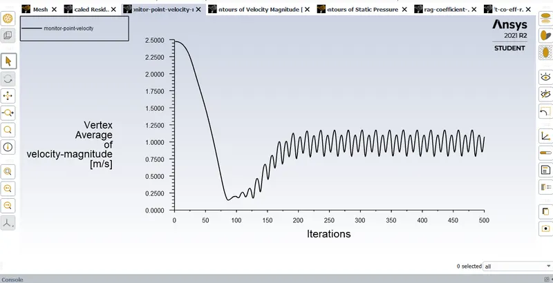
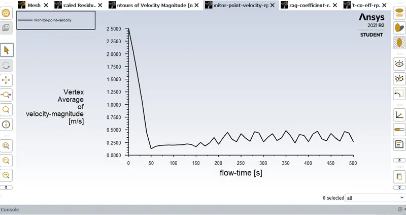
Co-effecient of drag plot
Steady state Re=100 Transient state Re=100
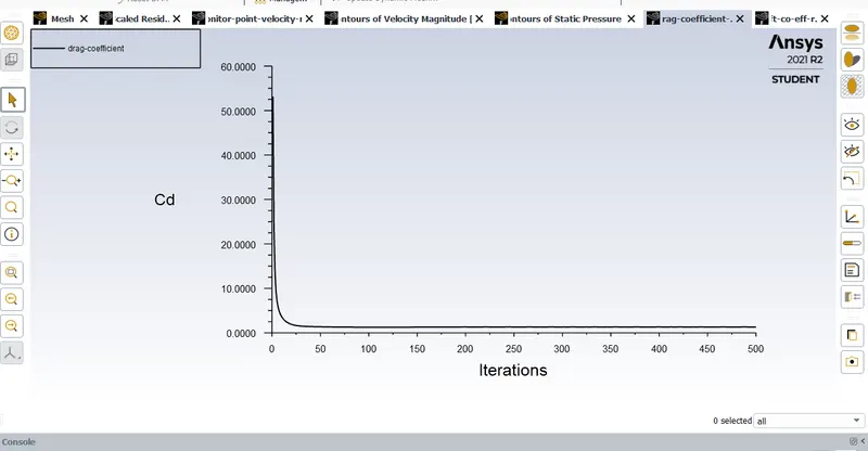
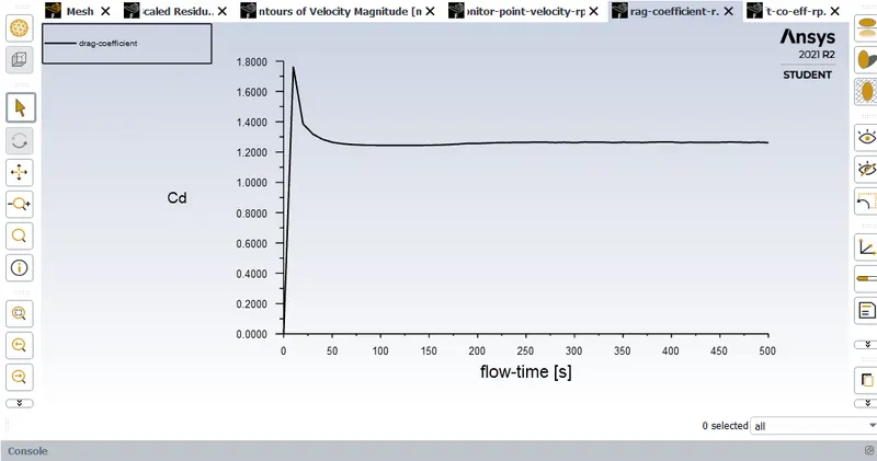
Co-effecient of lift plot
Steady state Re=100 Transient state Re=100
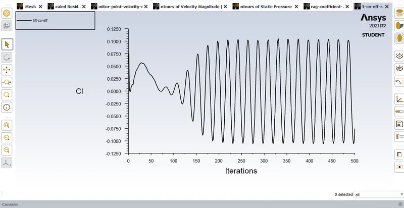
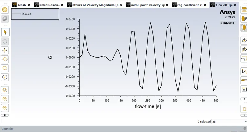
Strouhal number plot
Steady state Re=100 Transient state Re=100
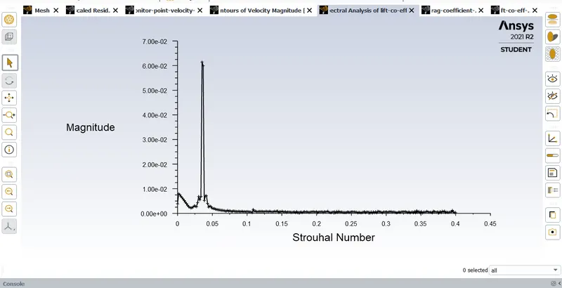
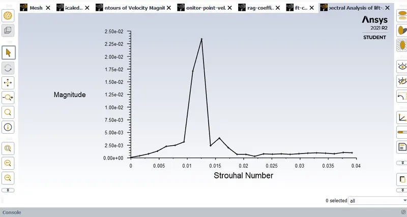
Strouhal number=3.642856e-01
Part 2
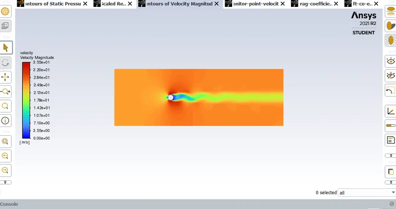
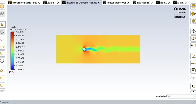
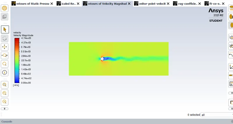
Velocity contours
Re=10 Re=100
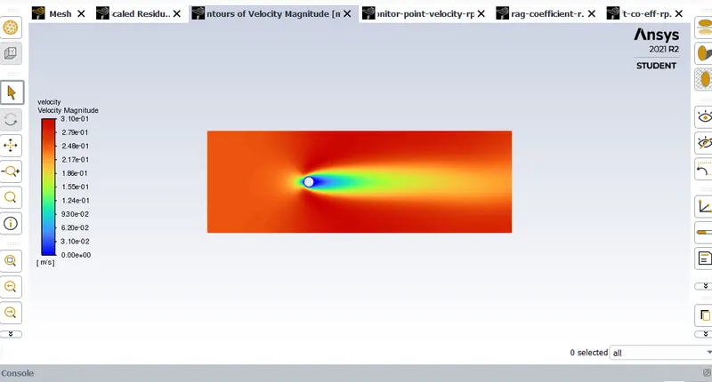
Re=1000 Re=10000
Re=100000
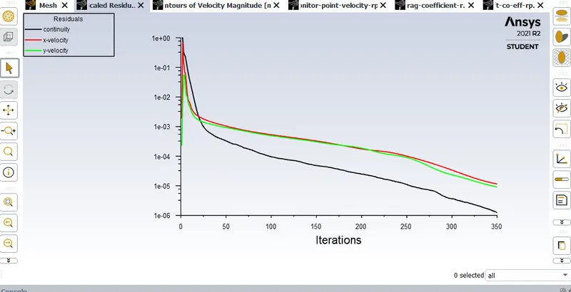
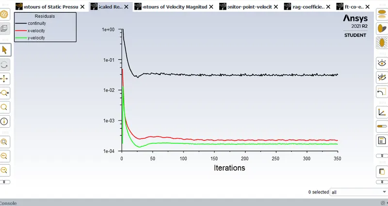
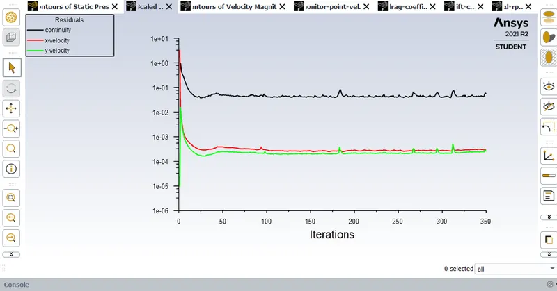
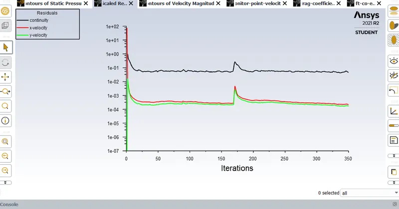
Residual plots
Re=10 Re=100
Re=1000 Re=10000
Re=100000
Vertex average of velocity magnitude plot
Re=10 Re=100
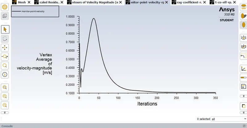
Re=1000 Re=10000
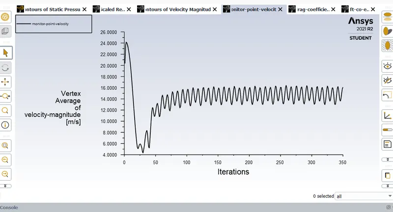
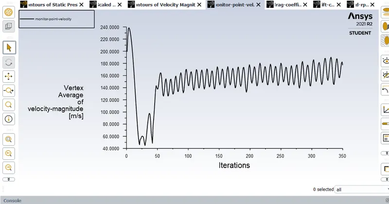
Re=100000

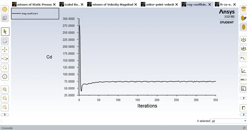
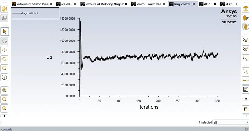
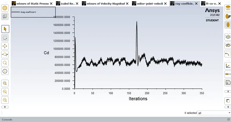
Co-effecient of drag plots
Re=10 Re=100
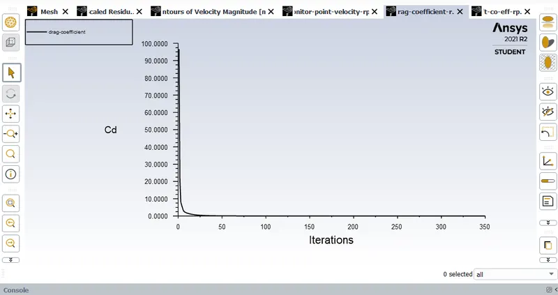
Re=1000 Re=10000
Re=100000
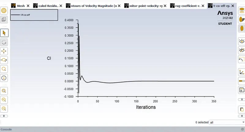
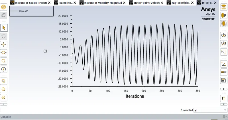
Co-effecient of lift plots
Re=10 Re=100
Re=1000 Re=10000
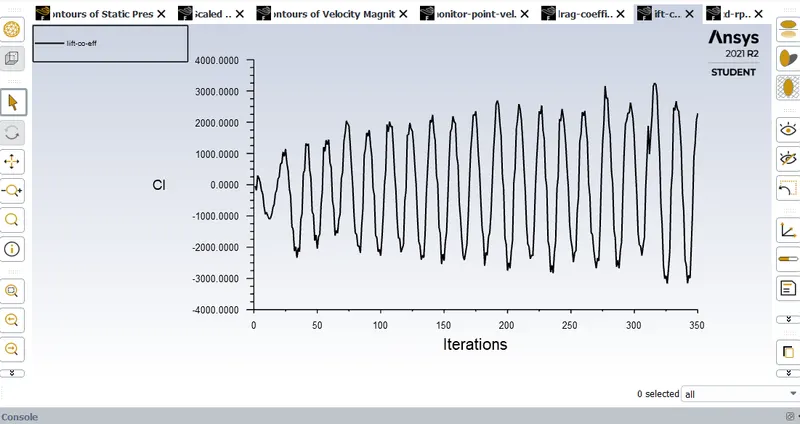
Re=100000
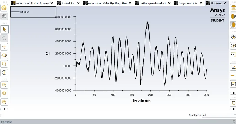
CONCLUSION-
1.In case of stable and unstable laminar fluid flow,for reynold's number 100, it is observed that time-dependent momentum equations result in lower vortex shedding.Hence, transient method is more effecient in resolving vortex shedding.
2.With increase in reynold's number,the fluid flow is observed to turn turbulent rather than laminar, moreover, turbulance in the flow increases with increase in reynold's number
3.In addition, the co-effecient of drag is observed to be directly proportional to reynold's number and also fluctuations in co-efficient of lift are found to rise with an increase in reynold's number
4.In general, it can be infered that viscosity being inversly proportional to reynold's number results in dominance of drag and lift forces over viscous forces, consequently transforming the flow from laminar to turbulent in a gradual fashion.