Week 2 Challenge : Surface meshing on a Pressure valve
Aim: To mesh the given geometry by using the given properties a by following the standard Meshing procedure.
Objective:
- Import the geometry.
- Check for any anamolies in the geometry.
- Fix the error or missing elements.
- Create a regional PID for each individual component of the valve.
- Do a Geometry check up.
- If there are any errors fix it (Intersect, Surface corrections etc.).
- Mesh the individual components of the valve.
- Create the three different cases as given in requirements.(Target length = 1mm, 3 mm and 5 mm)
Content of the body:
- Importing the geometry:
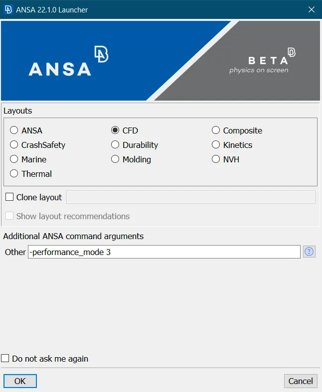
- Increase the performance of the ANSA:
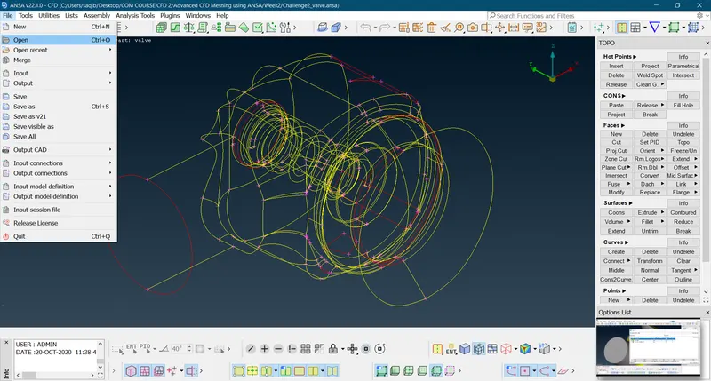
- Open the geometry by using the File > Open command > select the geometry:
- Increase the performance of the ANSA:
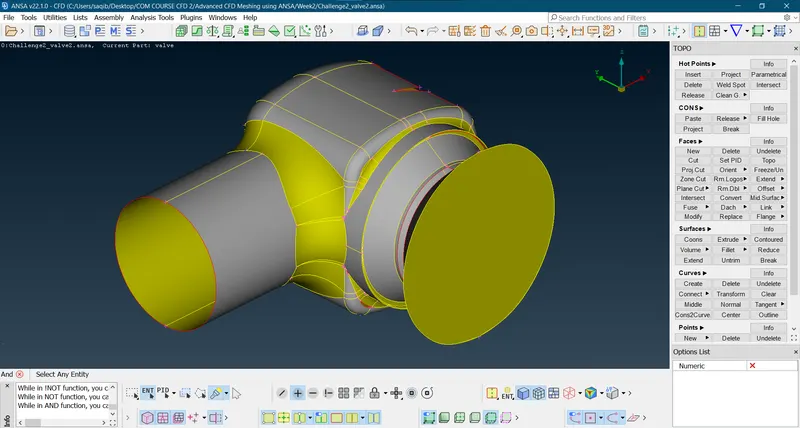
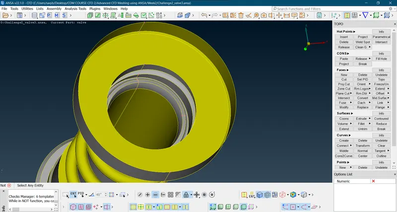
- Now using not and PID region select the outer body of the wall and hide it.
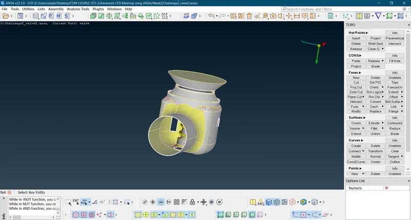
- Now as the outer body is selected using middle mouse button hide it using the not command.
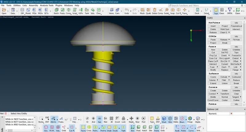
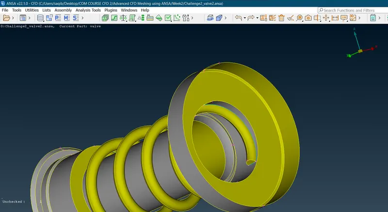
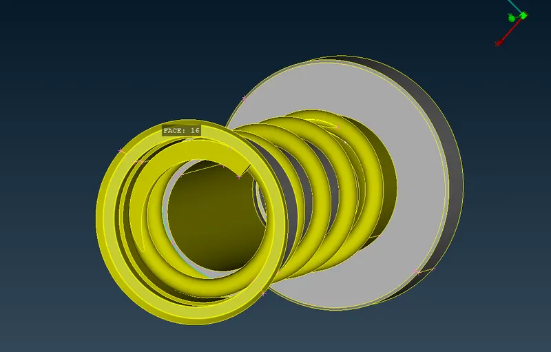
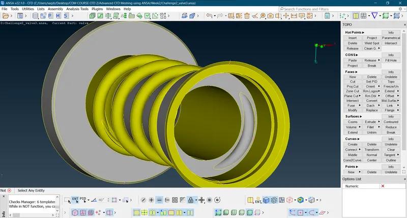
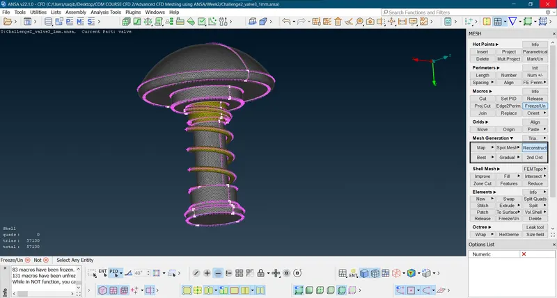
- Only spring, head and column are visible:
- Now hide the head of the plunger using not command with element selection:
- Fill the base of the column using the new command from face, use the loop here as it will encircle the perimeter beyond the hotpoints:
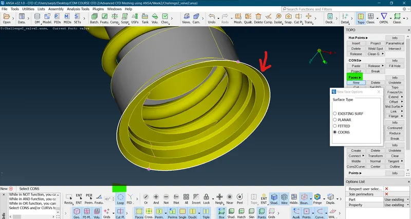
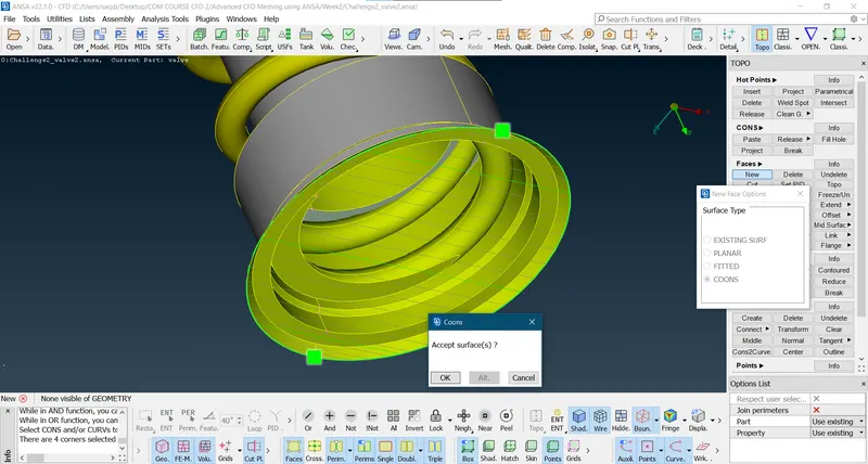
- The above step is deleted in the further steps to be followed.
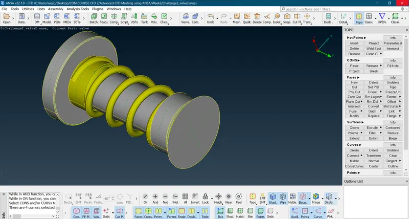
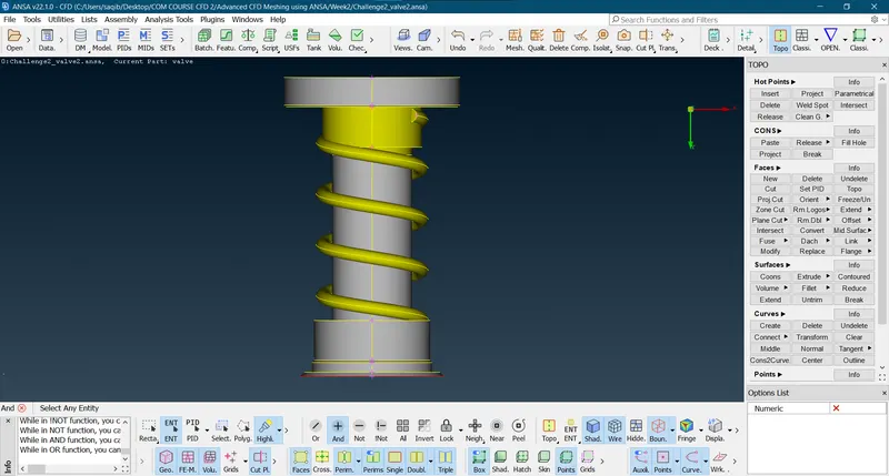
- Create the PID region for spring and column:
- The spring is named as spring and applied to the respective part.
- The column is named in the shell property and applied.(by selecting the PID region option from the tool bar)
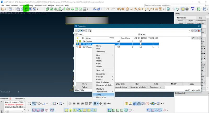
- Use the intersect(Face) option to intersect the geometriess viisble to create cons at the intersection and seperate the surfaces:
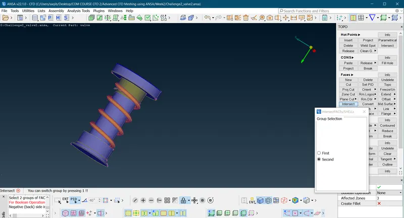
- First part is selected as the spring and second part as column. (left click + middle mouse)
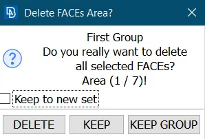
- Select keep option or close the popup as we will be deleting the faces manually.
- Now stsrt by deleting the intersecting faces using the delete option from the tool bar:
- Before deletion:
- After deleting triple cons:
- Deleting the extra cons:
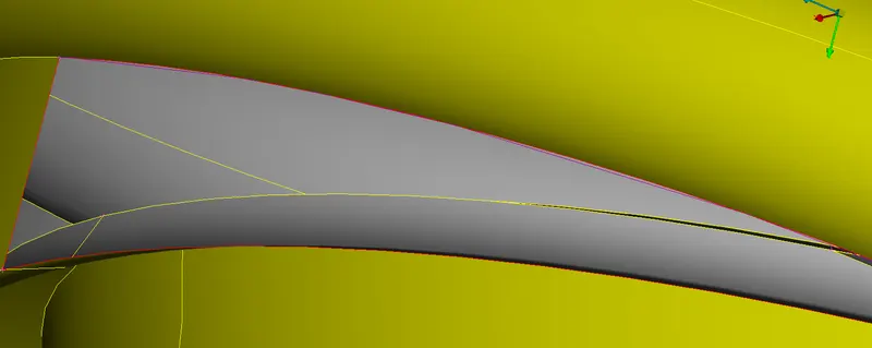
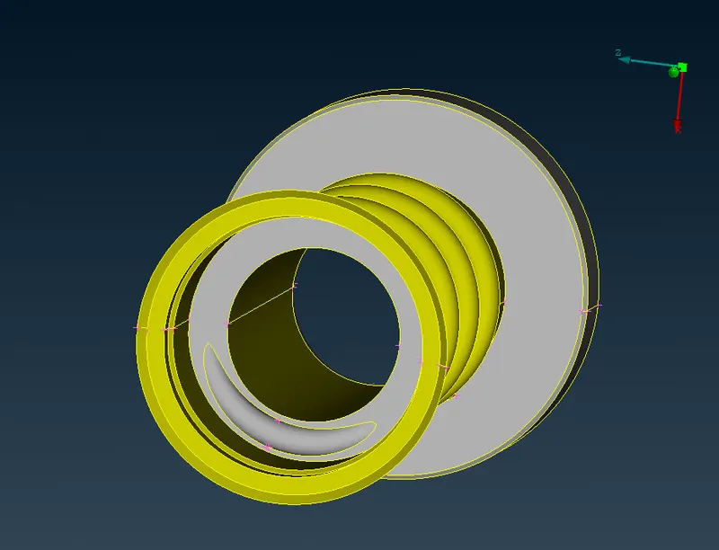
- Now deleting the inward pushed faces and replacing the surface with new face:
- Add new curve using cons2curve:
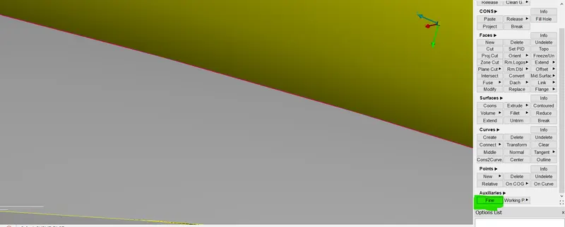
- Increase the resolution of the curve using fine command;
- New surface:
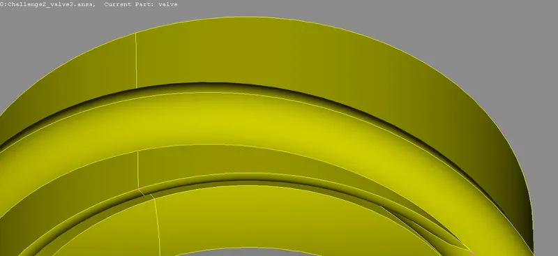
- Delete the curve.
- Removing the double cons:
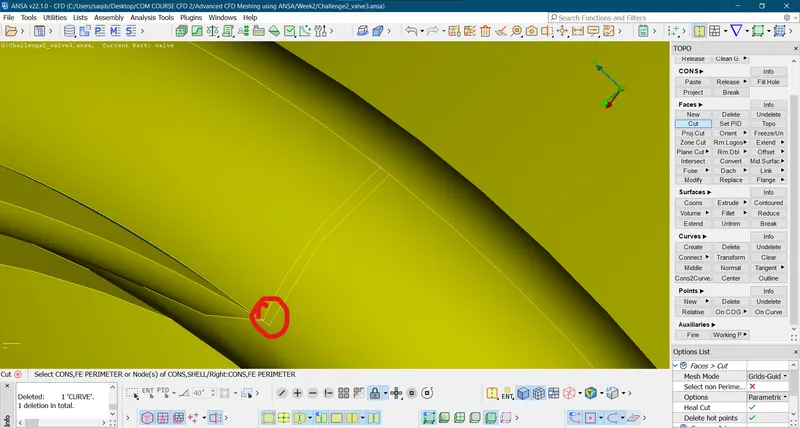
- Create extra cut and delete the curve and new surface using fill hole:

- Add new curve using cons2curve:
- Now delete the remaning spring parts intersecting:
- Before deletion:
- Run the geometry check:
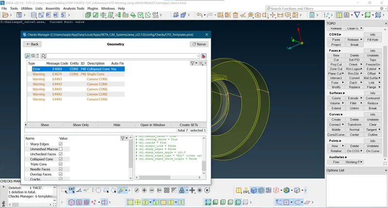
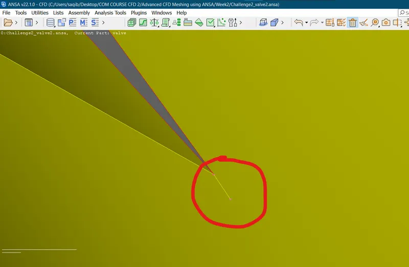
- Since it is a collapsed cons (starting and ending point are same) use autofix to fix it and again running the check:
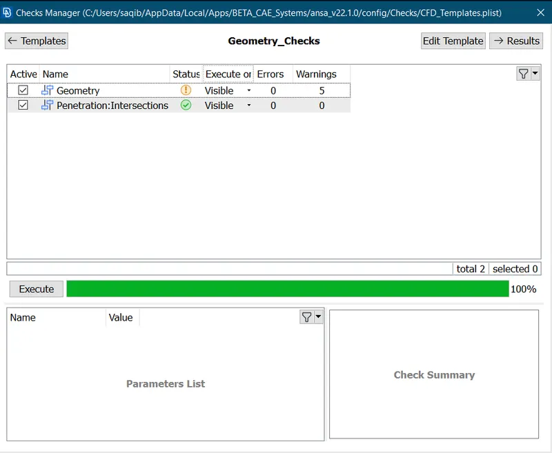
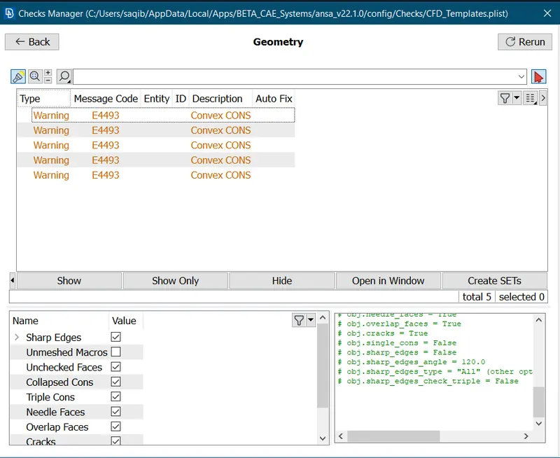
- The warnings are of the convex cons so for now it does not concern us.
- And the colapse coons are fixed by using the autofix.
- As all the issues are solved we can proceed to the next step.
- Now after deleting the intersected part of the spring and column:
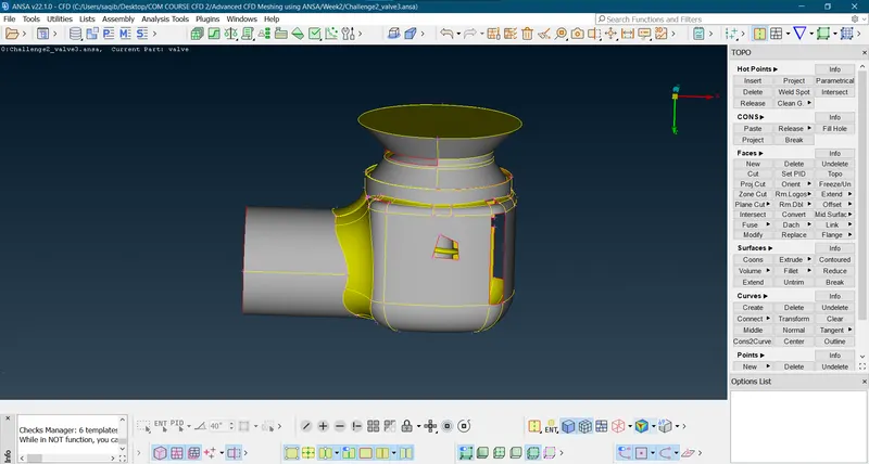
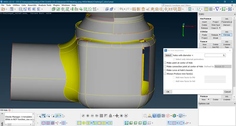
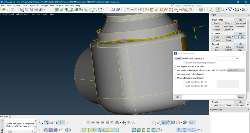
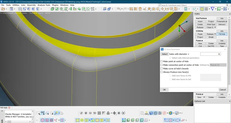
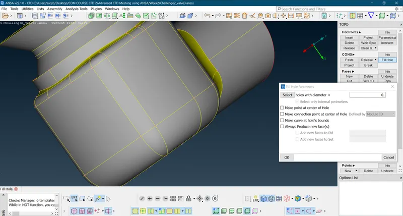
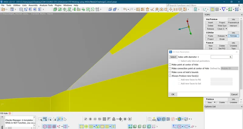
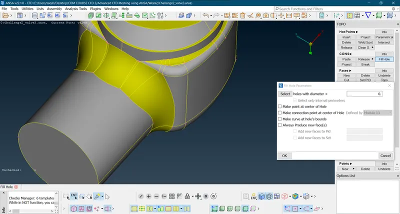
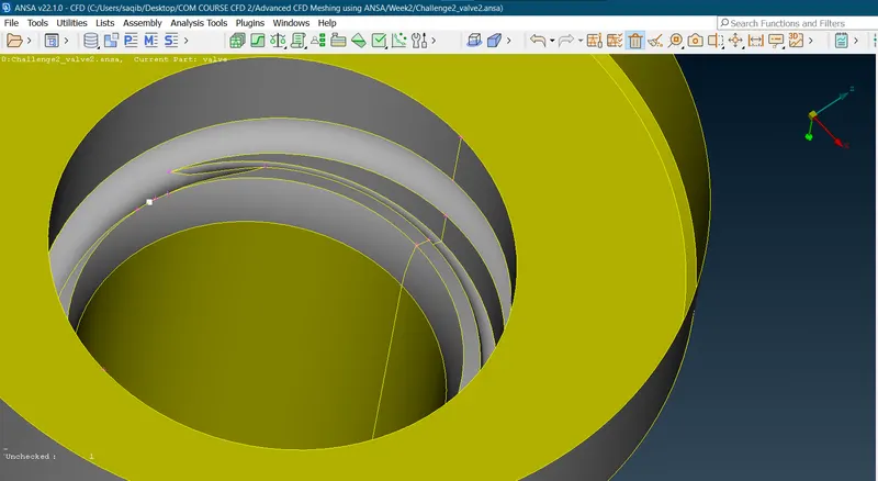
- Now fixing the outer casing surface errors:
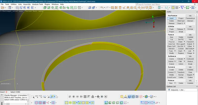
- Inserting the hot point:
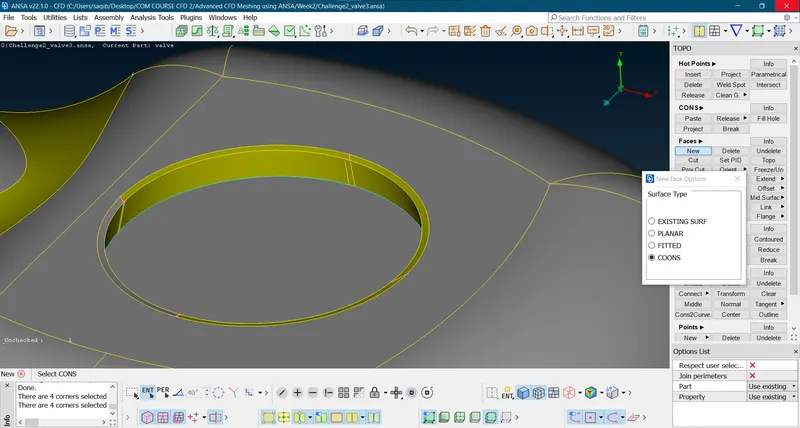
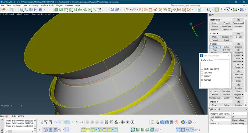
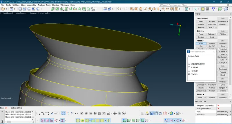
- Running the geometry check:
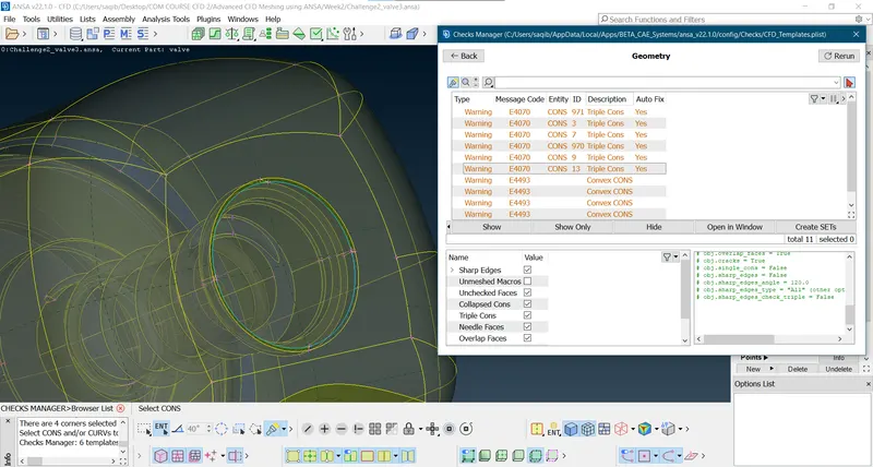
- All the triple cons are justified by the base of the column.
- The PID's are defined and the compression io done to delete unused/repeating PID's.
- The PID's are defined and the compression io done to delete unused/repeating PID's.
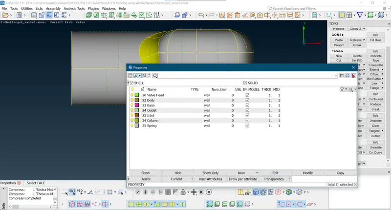
- Now uncut the geometry to eleminate any sharp edges while meshing:
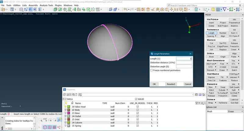
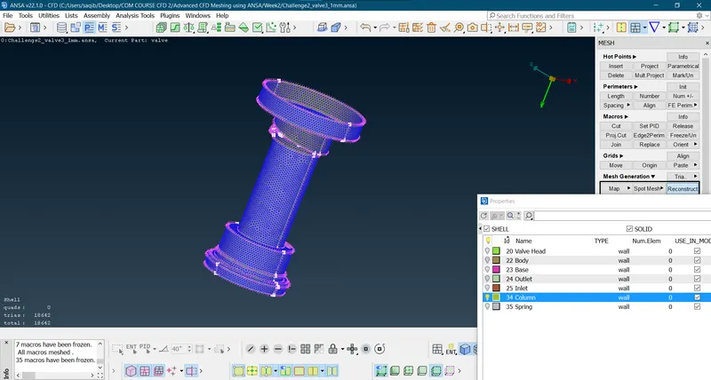
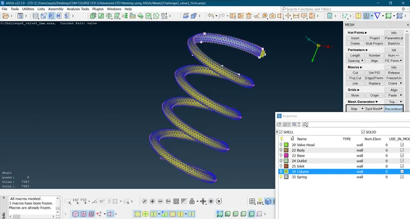
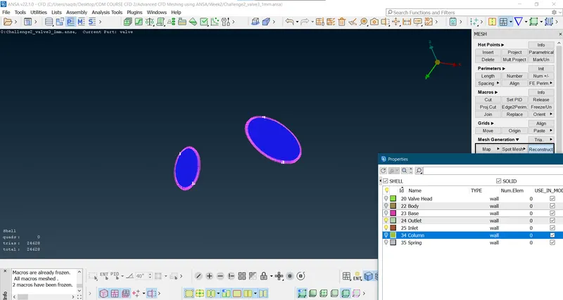
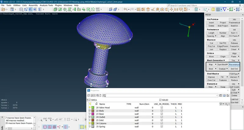
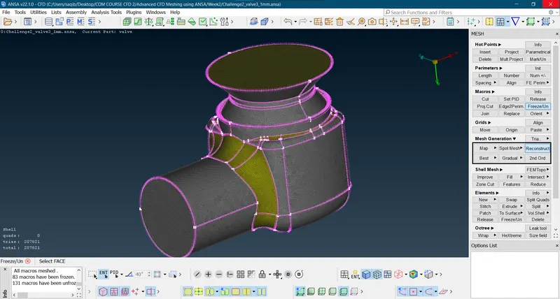
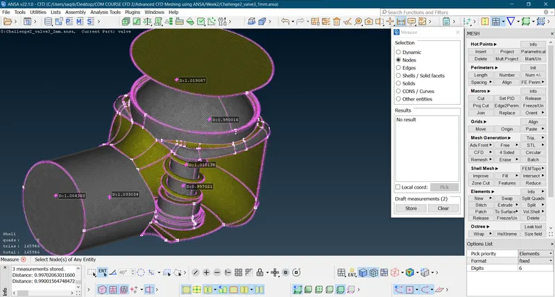
- Meshing (1mm):
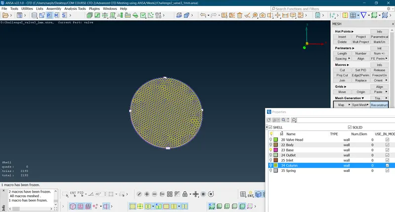
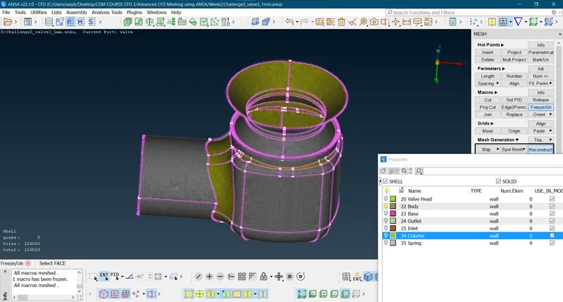
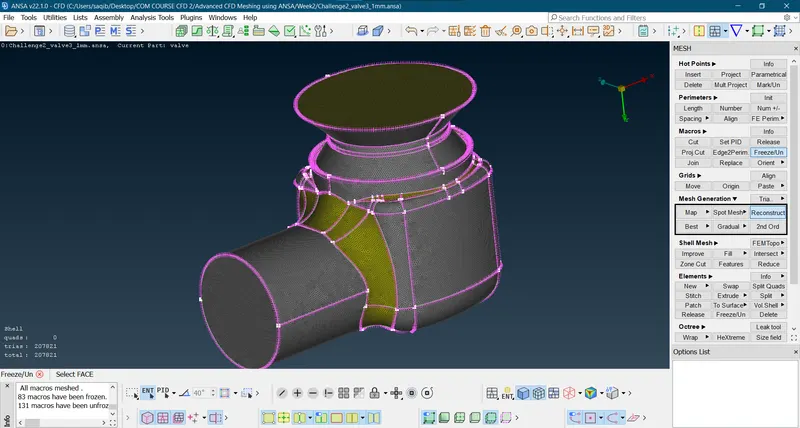
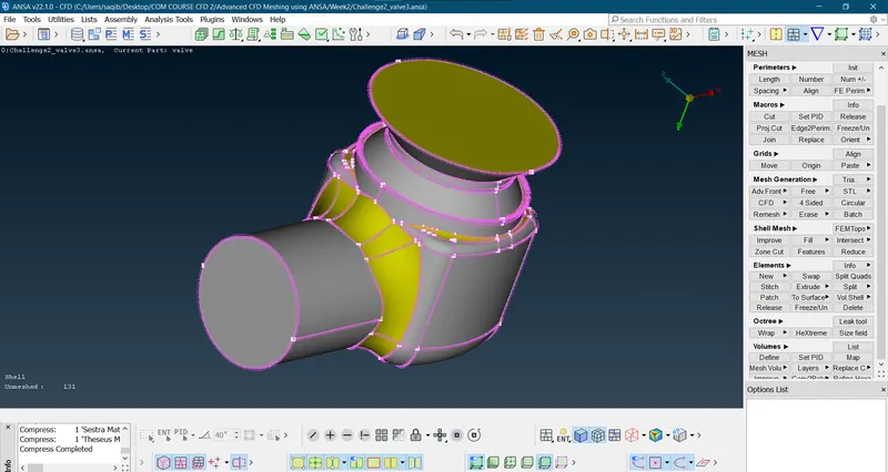
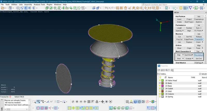
- Create a spot mesh of perimeters and macros of 1mm.
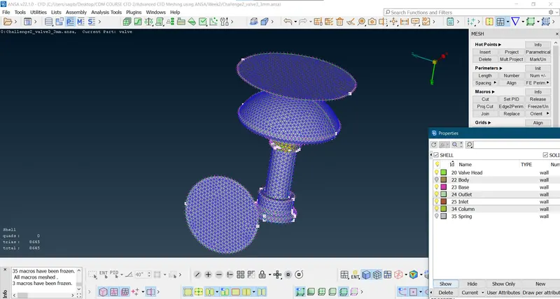
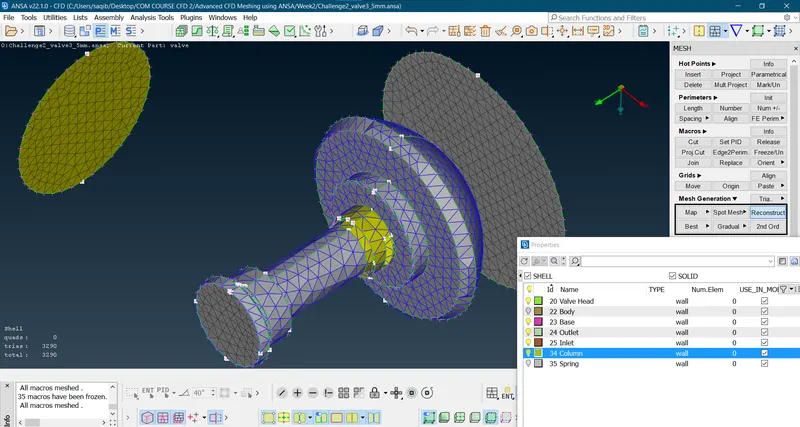
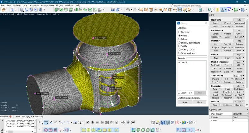
- Meshin (3mm):
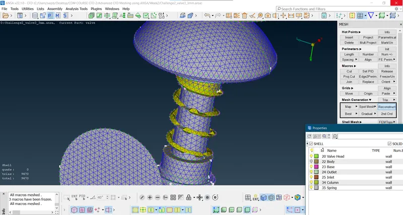
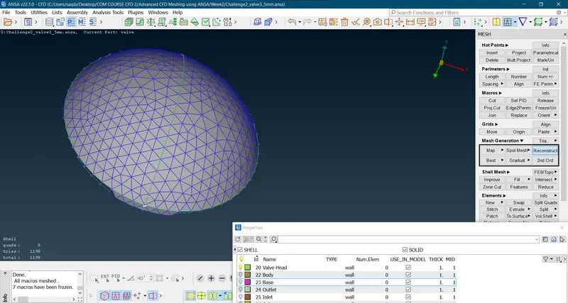
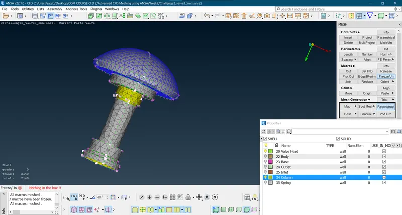
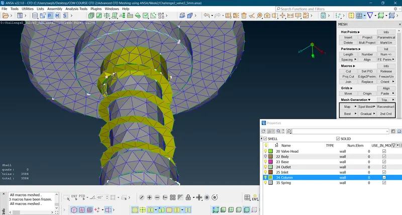
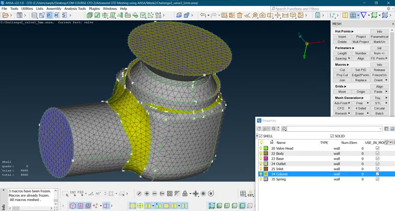
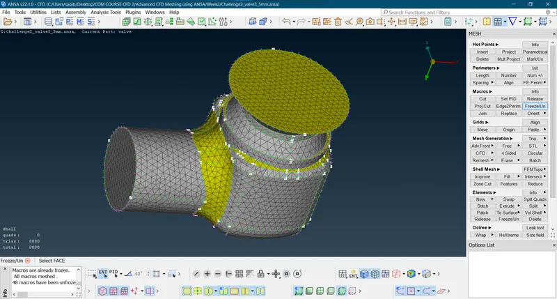
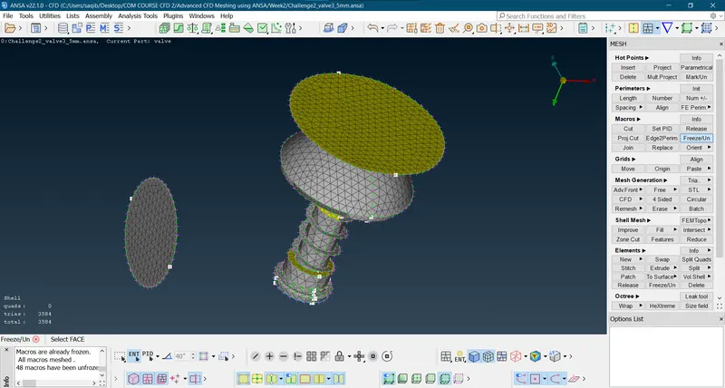
- Meshing (5mm):
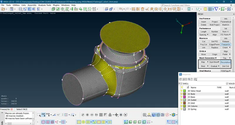
- By selecting the single PID each time spot mesh the entire geometry.
- Freeze(blue colored) the PID after it has meshed to avoid any interference causing the errors.
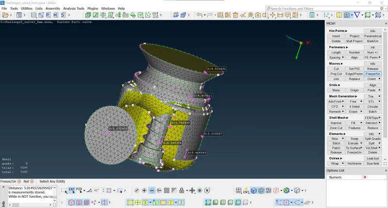
- Measure the nodal distance to verify the mesh obtained.
Results:
- Meshing (1mm):
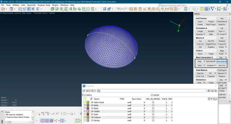
- Meshing (3mm):
- Meshing (5mm):
Learning outcomes:
- Cleaning the geometry.
- Fixing the surface errors.
- Meshing.
- Effect of Resolution/Target length variation.
- Creating and selecting the optimum mesh paramters for the analysis.
Links to the geometry files:
- https://drive.google.com/file/d/1FxkrGNF3zpy6_LD_w9Ed1PpPqUOEVKsf/view?usp=sharing
- https://drive.google.com/file/d/1p8Cmi19jsG2WDSlZGoooQZk1Z_Qt1EYW/view?usp=sharing
- https://drive.google.com/file/d/1kwuvHtolU5kezjlytPjYd_P4koe4fFFt/view?usp=sharing
- Rar File: https://drive.google.com/file/d/1HUHnBpeEDHObfDSIxZOy8BnDcbpew_YR/view?usp=sharing
Conclusions:
- The geometry cleanup and topology cleanup are performed on the geometry successfully.
- The geometry is meshed for three different element size i.e. Target length = 1mm, 3 mm and 5 mm.
- Less the Target length high is the surface mesh resolution (and nodes) and vice versa.
- For more accurate results use very low target length(high resolution) but this must not invertly interfere in the design of the geometry.
- The procedure and the results are explained in detail with the corresponding figures.