Week 2 Challenge : Surface meshing on a Pressure valve
AIM:
This project aims to generate a surface mesh on a pressure valve using three different mesh sizes and find out the optimal mesh size.
OBJECTIVES:
- Check for the geometrical errors and perform Topology cleanup.
- Set three different target lengths as three different cases and mesh the model. Target length = 1mm, 3 mm and 5 mm (i.e., 3 cases).
- Element type to be used is triangular.
- Apply any one target length from the above at a time for the entire model as one case thereby create 3 different models for 3 cases.
PROCEDURE:
Step 1 -
The first step we need do is import the given geometry and do a geometry checkup to find out all the errors that are present in the imported geometry.
Geometry -
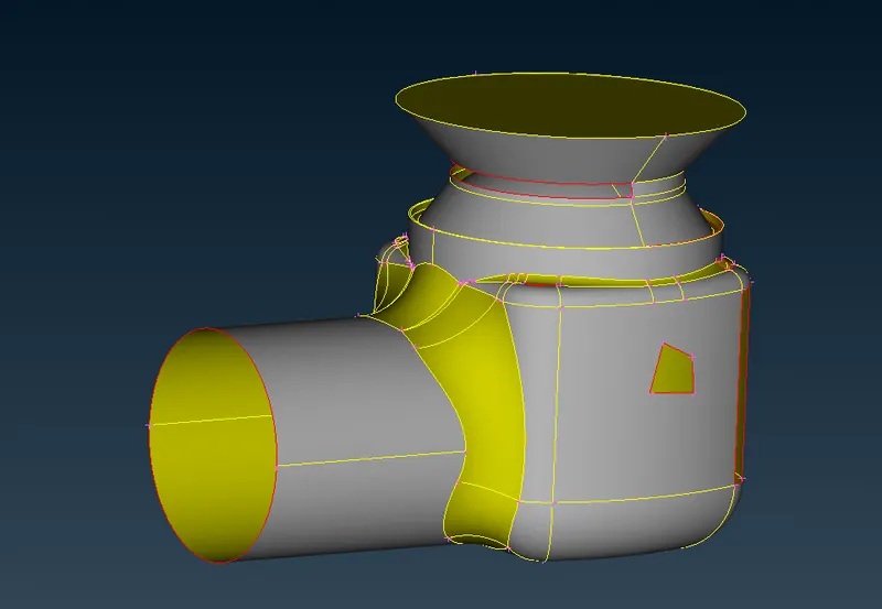
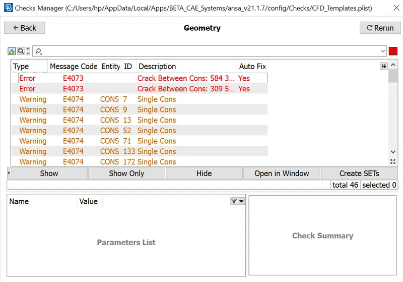
As we can see we have many single cones and gaps/open faces in the geometry, ANSA counts both of these as errors, as shown below after doing the geometry checkup also. So, the first thing we need to do is correct these errors.
Geometry checkup -
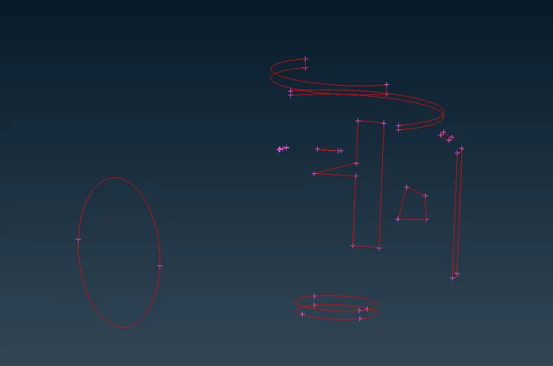
In order to see all the errors/single cons, we can turn off the shadow of the figure and turn off double and triple cons, so that we can see only single cons properly as shown below.
Single cons -
There are many ways to correct these errors like; using "New Face" option, using "coons" option in surfaces or using "Fill Holes" option under cons. The option we're going to use id the "Fill Holes" option as it fills the holes in a surface without creating a new surface and hence give a better single surface rather than multiple surfaces.
Fill Holes option -
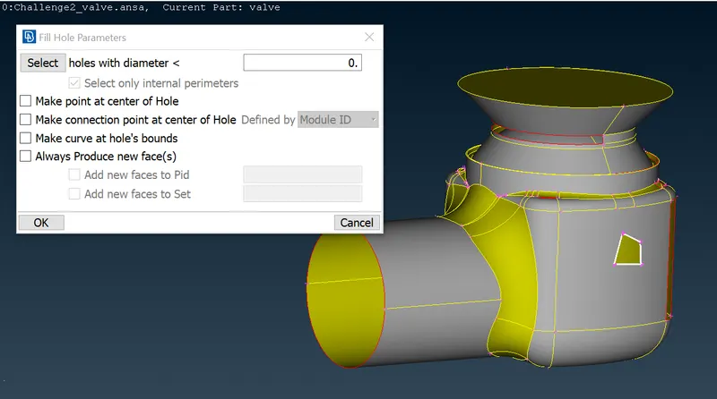
After selecting the fill hole option all we need to do is select any hole as shown above and click the middle button of the mouse. We can do this for all the holes and we'll get a clean geometry as below.
Cleaned Geometry -
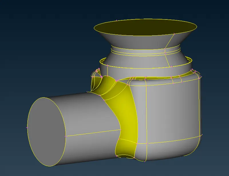
We can once again do the geometry check in order to verify the geometry.
Geometry checkup -
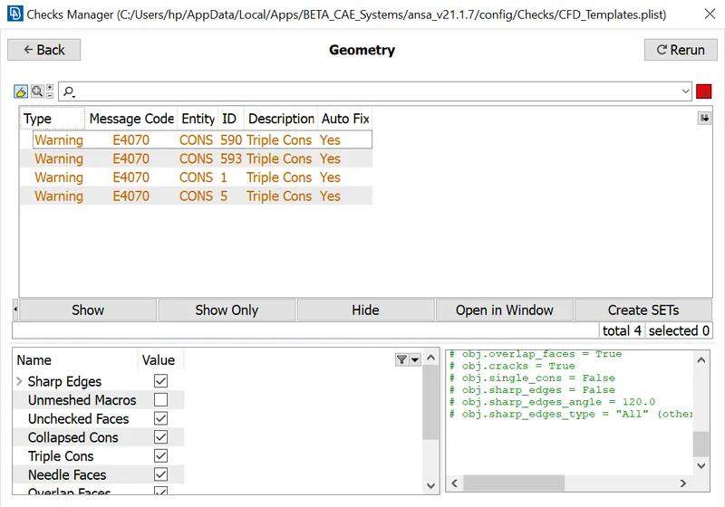
As we can see from above there are still 4 warnings, but these warnings are for triple cons and in order to create a water tight geometry for analysis we need these triple cons and hence we'll just ignore these warnings and proceed to next step.
Step 2 -
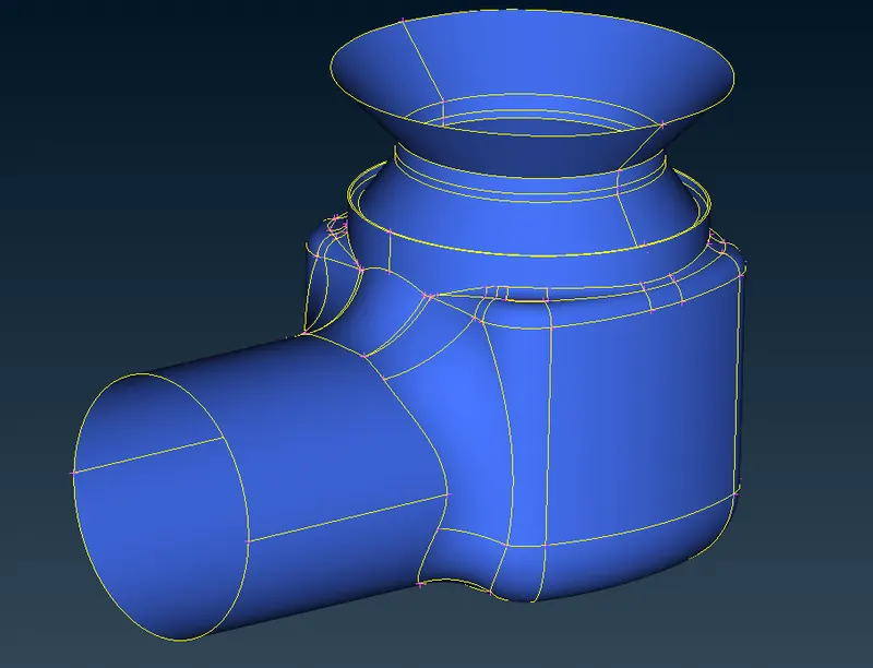
In this next step we'll divide the single PID model into several different PID in order to mesh the model more accurately and easily.
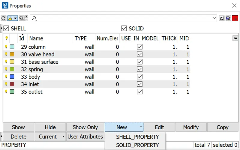
To create a new PID we'll open the PID manager, we'll add new PID by clicking on the "NEW" option present at the bottom options and under "NEW" option we'll select "Shell parameters".
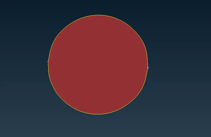
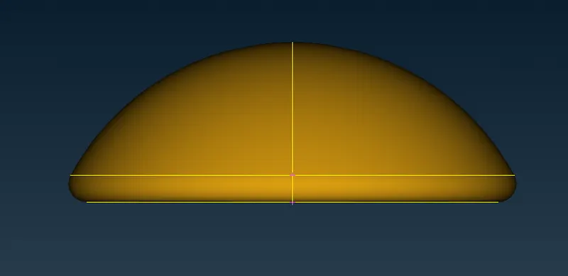
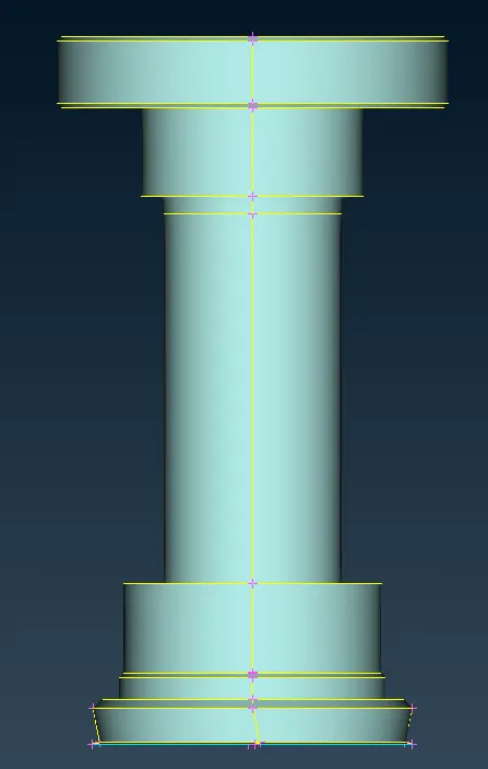
We'll create 7 PID (as shown below) and in order to assign each PID to a component all we need to do is click on the PID and then click on apply, after the select the required part, you want to assign to the selected PID and press the mouse middle button.
The PID list and all the different PID are shown below.
PID Manager -
Inlet -
Outlet -

Body -
Base Surface -

Valve Head -
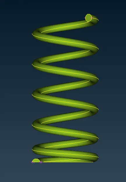
Spring -
Column -
Full Geometry in PID mode -
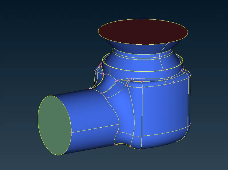
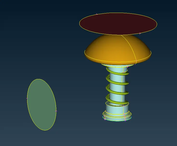
Step 3 -
CASE 1: Mesh Size - 5mm
Now we move to mesh mode from topo mode in order to mesh the given model.
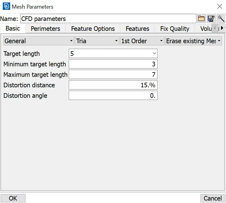
The first thing we need to do is open the mesh parameters (5mm for case 1) from the top option list and input the mesh parameters we want for the meshing of this geometry.
Mesh parameters for the given surface mesh is shown below.
Mesh parameters (5mm for case 1) -
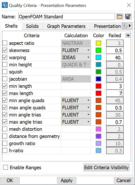
We'll also need to update the quality criteria according to our parameters as shown below.
Quality criteria -
As we're done setting up the parameters, now all we need to do is select the PID one by one in order to mesh them.
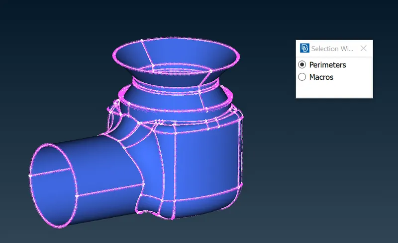
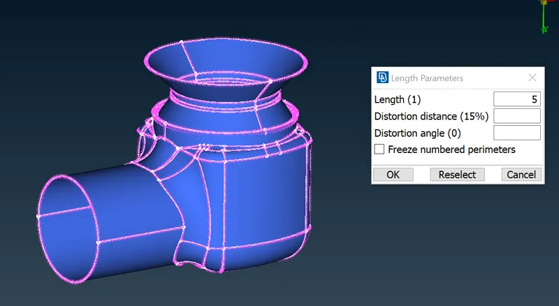
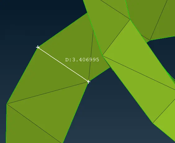
We use the length option in the Perimeters option to assign a length to all the edges(perimeters) and also to assign the mesh sizzing on the surfaces using the “Macros” option. We can cross check the distance between nodes using a measuring tool.
Surface meshing of body PID -
The first thing we'll do is isolate the body PID and then do the above mentioned steps.
Selecting the length option -
Providing the required mesh size -
We're done setting up all the required parameters and now we need to choose a meshing algorithm present in ANSA.
The algorithm we'll use is the "Spot Mesh" option.
Finale meshed body PID -
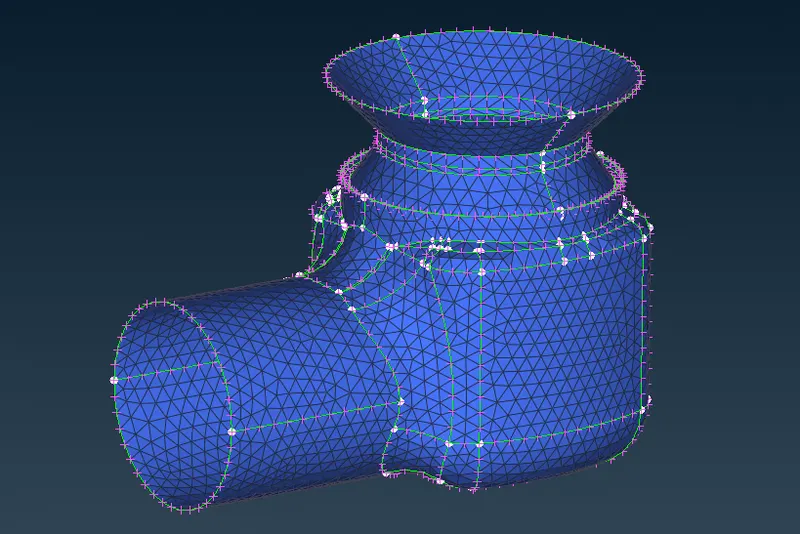
So, we're done meshing the body PID and similarly we can mesh all the PID's as shown below
Inlet -
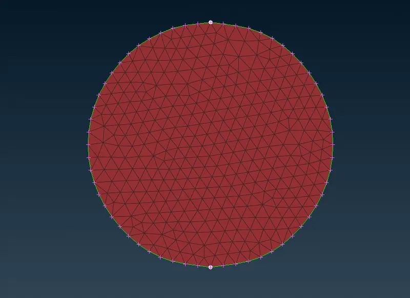
Outlet -
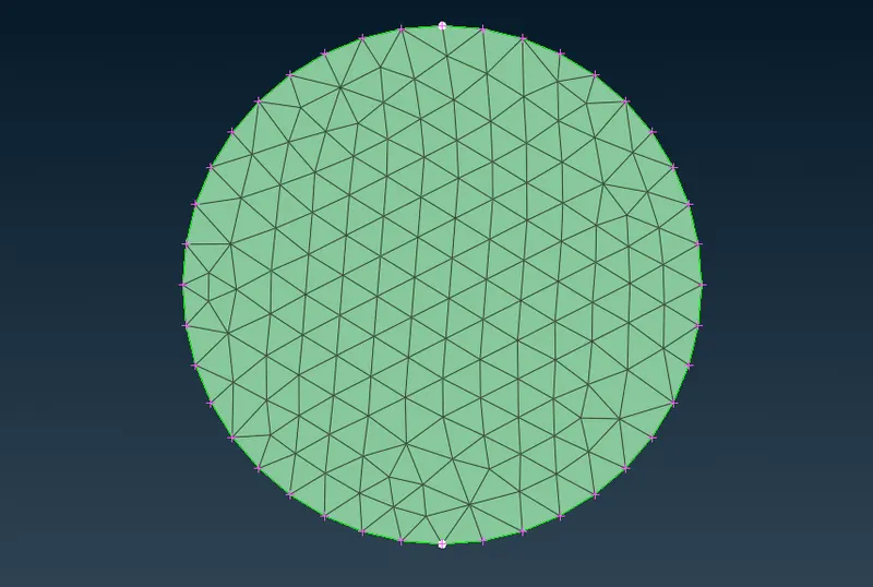
Base Surface -
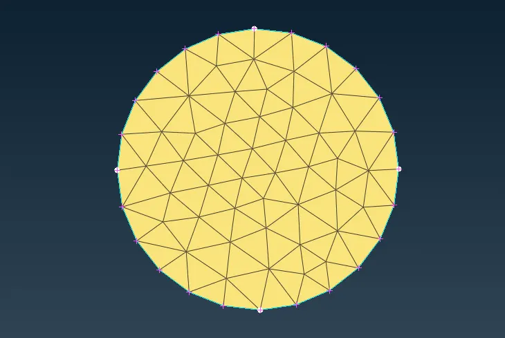
Valve Head -
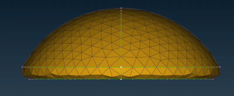
Spring -
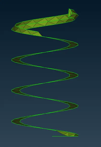
Column -
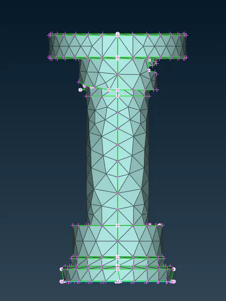
Whole Geometry -
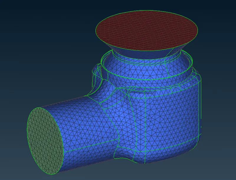
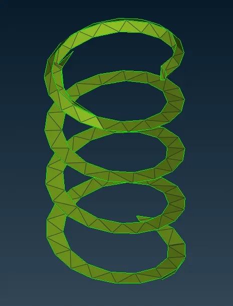
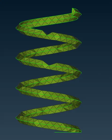
If we see the meshing on spring and around the valve head corners, we can see that the meshing is very bad and in the case of spring, if we measure the diameter of the spring its around 3.4mm but our element size is 5mm and hence it’s not meshing the spring properly. So, we need to reduce our mesh size in order to have a good mesh.
Mesh Around Spring -
Total number of elements -
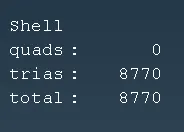
CASE 2: Mesh Size - 3mm
For this case the only thing we need to change is the mesh parameters and the rest of the procedure is same as above.
New Parameters -
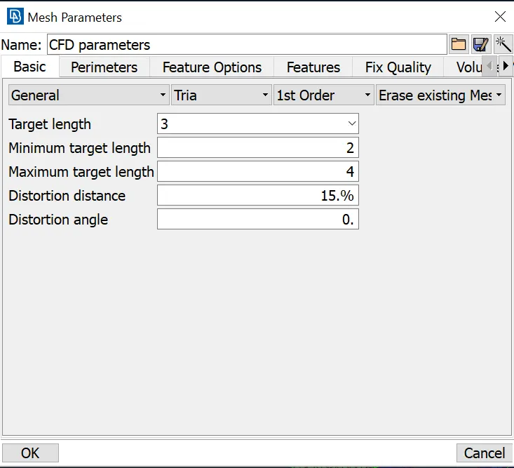
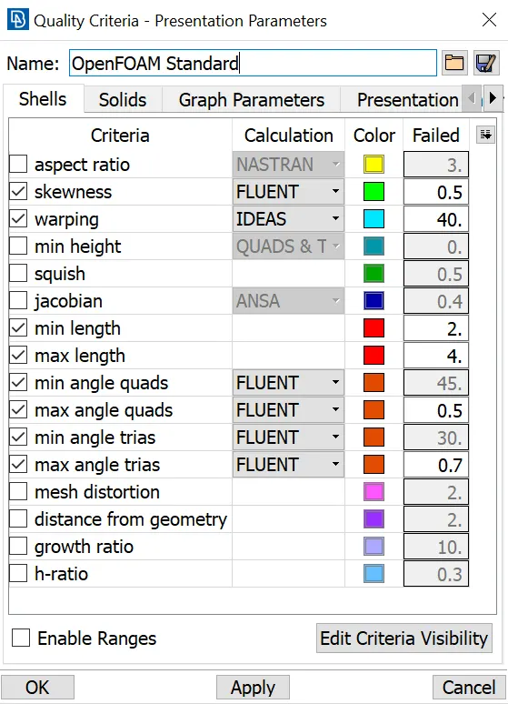
In the length option also, we'll enter mesh size as 3mm instead of 5mm.
Meshed parts -
Inlet -
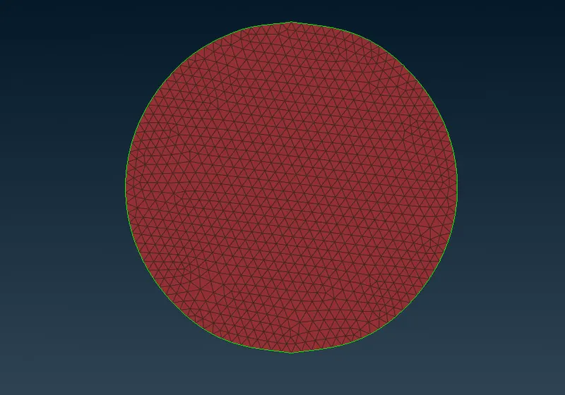
Outlet -
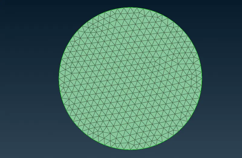
Body -
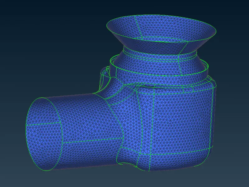
Base Surface -
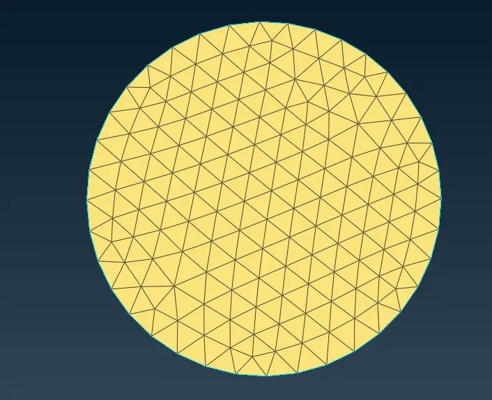
Valve Head -
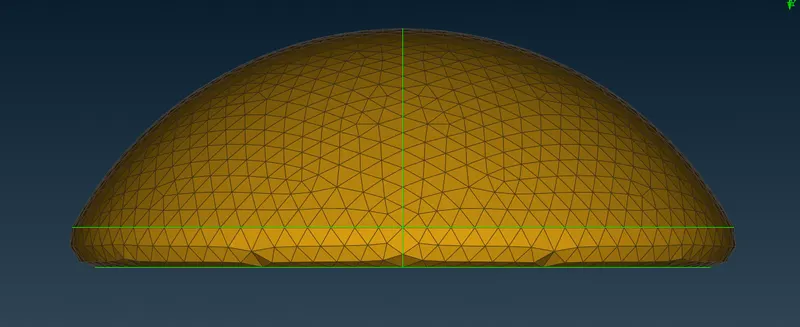
Spring -
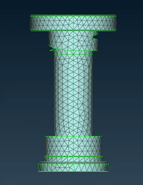
Column -
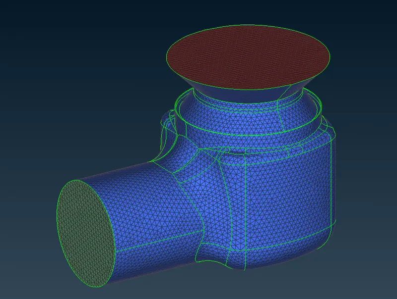
Whole Geometry -
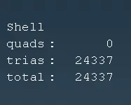
Total number of elements -
As we can see by reducing the mesh size, we improved the mesh quality but we're still not able to capture spring and the valve head properly and hence we need to reduce our mesh size more.
CASE 3: Mesh Size - 1mm
For this case the only thing we need to change is the mesh parameters and the rest of the procedure is same as above.
New Parameters -
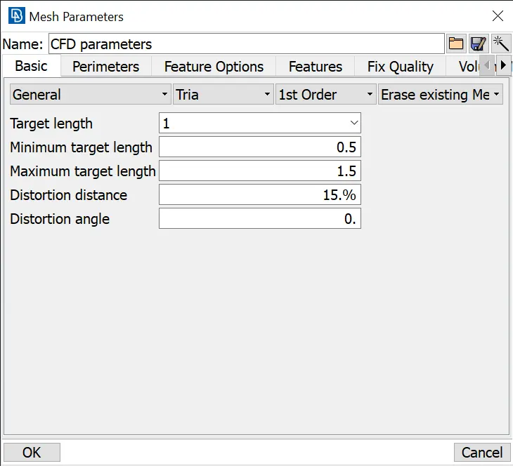
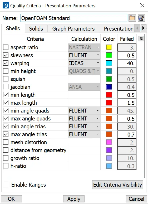
In the length option also, we'll enter mesh size as 1mm instead of 3mm.
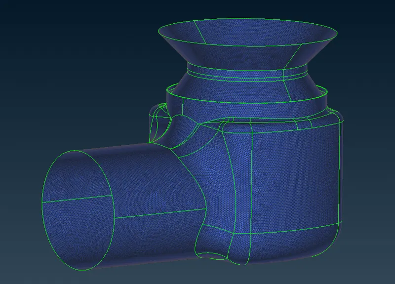
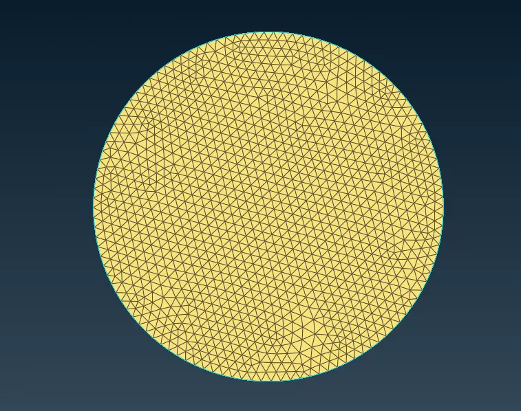
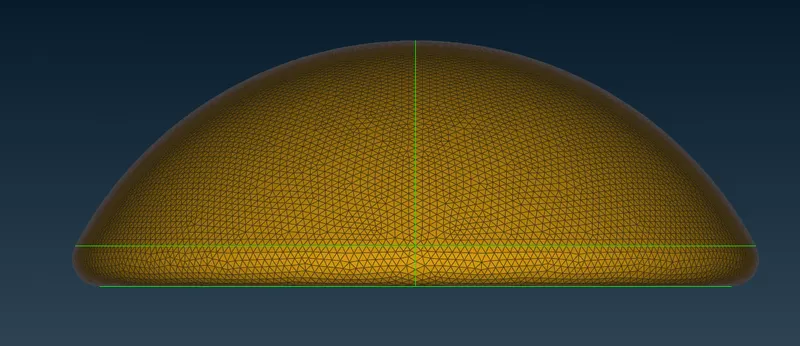
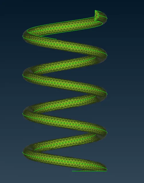
Meshed parts -
Inlet -
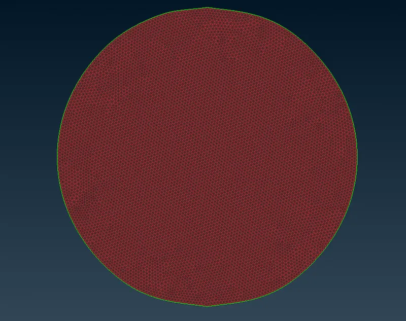
Outlet -
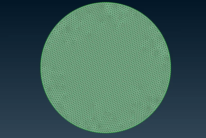
Body -
Base Surface -
Valve Head -
Spring -
Column -
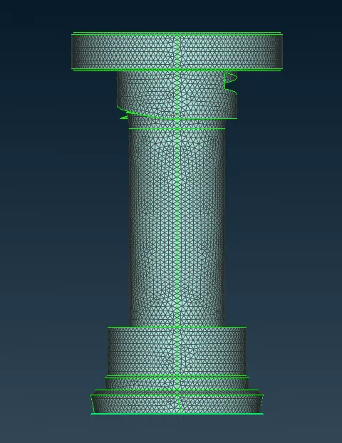
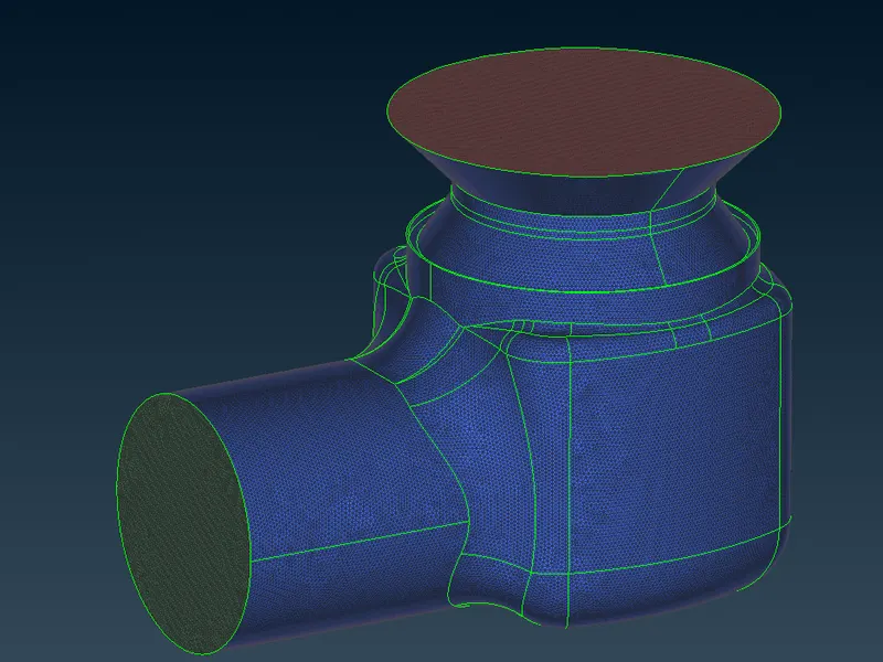
Whole Geometry -
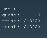
Total number of elements -
CONSLUSION:
- From the above 3 cases it can be concluded that the case 3 with 1 mm target length has little to no defeaturing and has retained the geometry of all components.
- Hence case 3 is giving the best results. But on the flip side it increases the computational time.
- To decrease the computational time the number of elements need to be decreased without having defeaturing. To achieve this the components whose size is less or equal to the mesh size needs to be meshed individually with different mesh size.