Week 2 Challenge : Surface meshing on a Pressure valve
AIM: Studying the surface meshing on ANSA for a pressure valve.
GEOMETRY: The provided geometry required a lot of clean up of empty spaces in order for proper CFD Applications.
This can be done from within the ANSA software itself. The first step is to do a "geometry check" which can let us know of all the open CONS available in the geometry that need to be fixed.
After the number and location of CONS is identified, we can use the "New Faces -> COONS" Option from the TOPO deck.
After fixing, the geometry looks like this:
Now that the geometry has been cleaned up, we can begin meshing. For a complex geometry like this, we must assign PDI to each component to help with the meshing process and to regulate any additional geometry cleanup or selection. By doing this, handling the complex geometries during meshing becomes very simple.PID is used to define the boundary conditions of a geometry for CFD Applications.
The number of PID's created are as follows:
Some of the individual PID's are:
As demonstrated, by selecting new, a new PDI is created and assigned to any part.
The PDI's side bulb indicator indicates that it is visible.
MESHING:
- Target length 1mm
Minimum length = 3mm
Maximum length = 5mm
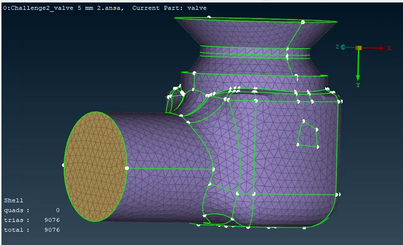
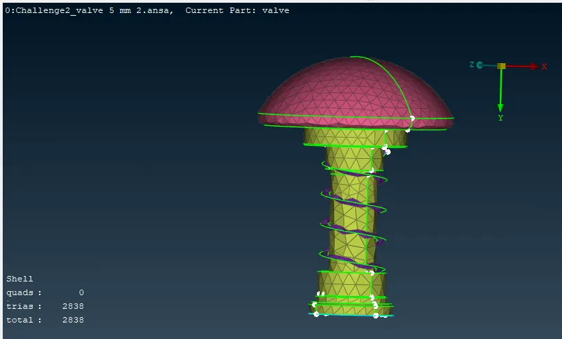
CASE 1: 1 mm
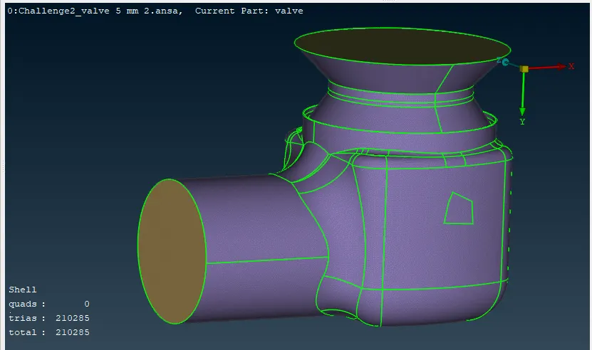
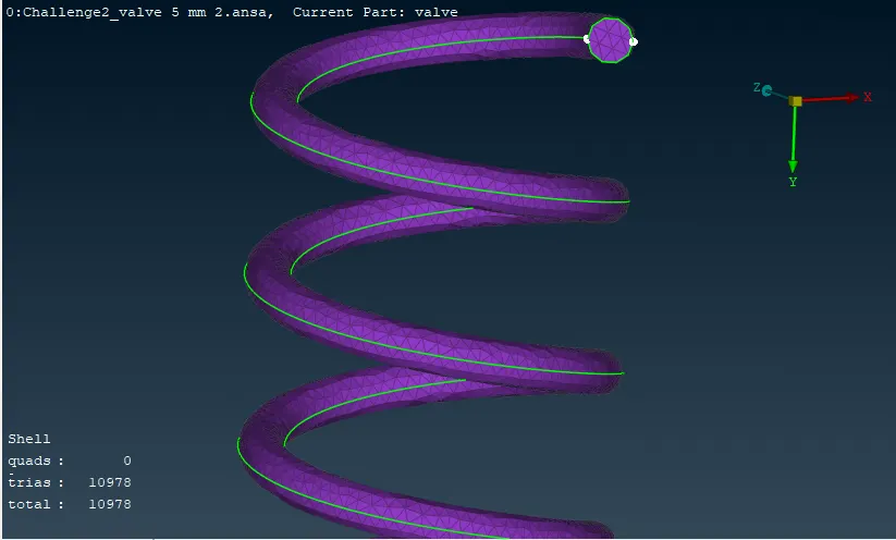
CASE 2: 3mm
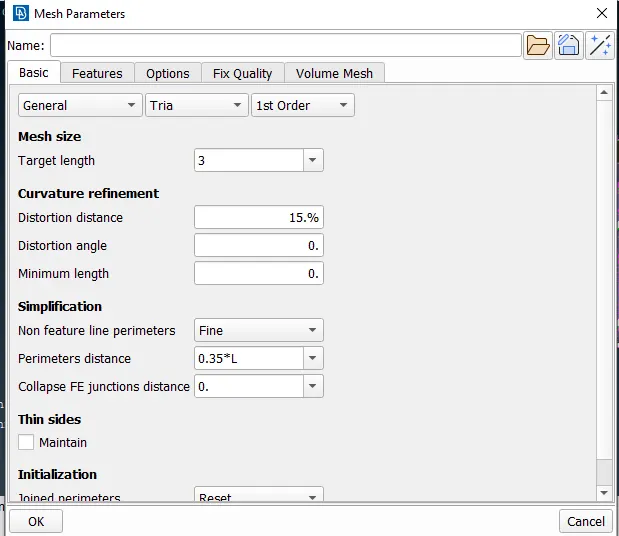
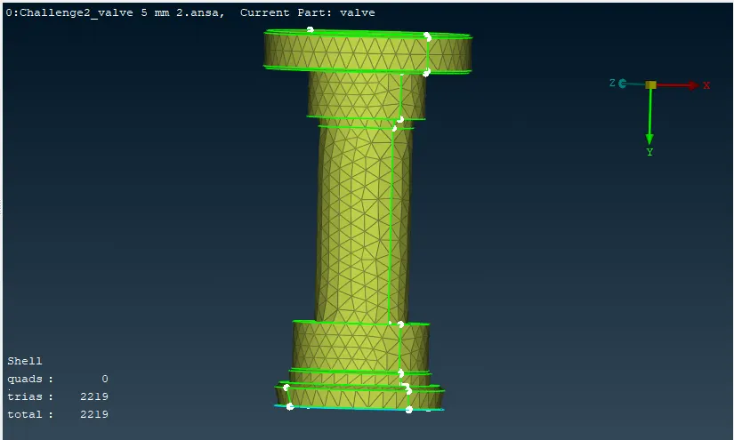
CASE 3: 5mm
CUNCLUSION:
- Fine mesh sizes improve accuracy, but they can lengthen calculation times.
- Depending on the parts size and necessary accuracy, we can create two distinct target lengths. In this instance, the outer casing mesh size can be 3mm, which is neither too big nor too fine for a good and accurate outcome.
- The precision of smaller parts rises as well since the mesh length for smaller parts, such as the spring and column head, can be 1 mm.