Week 2 Challenge : Surface meshing on a Pressure valve
Aim:
To perform (i)topology clean up (ii)Checking geometrical errors (iii) meshing for three different target lengths of 1,3,5 mm with the element type of triangular using ANSA.
Introduction:
ANSA is an advanced CAE pre-processing tool for Finite Element Analysis that provides all the necessary functionality for full-model build up, from CAD data to ready-to-run solver input file, in a single integrated environment. CAD geometry can be read in and manipulated by ANSA's powerful built-in geometry engine. Following the mesh area idealization, geometry can be meshed according to modeling requirements by its fully integrated surface and volume meshing functionality. Furthermore, the integrated batch meshing tool leads to optimal meshing results. Powered with comprehensive parts and welding management tools, ANSA allows parts assembly, with alternative connections types. Pre-processing completion is achieved through the uniquely interoperating pre-processing decks for NASTRAN, DYNA, PAM-CRASH, RADIOSS, ABAQUS and ANSYS, allowing direct model modification between solvers. Apart from the formats of the solvers for which complete pre-processing decks exist, i.e. NASTRAN, DYNA, PAM-CRASH, RADIOSS, ABAQUS and ANSYS, numerous other file formats are supported, for structural, CFD and other solvers. The core pre-processing functionality of ANSA is enhanced with a substantial number of other advanced tools that allow the user to complete specialized tasks without leaving the software environment. Such tools are the Cross Section Analysis Tool, the BIW Bath Traps Tool and the Fuel Tank Analysis Tool. The ANSA Morphing Tool may be used simply for evolutionary changes or sensitivity analysis. The powerful ANSA scripting language allows the coupling of the Morphing Tool with any parametric script driven optimizer within a cycle towards optimal modeling. The ANSA scripting language is an enhanced programming tool that boosts productivity by giving to the user the power to access data and perform custom operations in an automated way.
Procedure:
1.ANSA appeared on the start menu.By clicking that,Launcher window will appear on the display.By default ANSA Layout will be selected,layout CFD is Changed and additional ANSA command arguments are by default is Change directory,Changed to -performance_mode 3 and then Ok button is selected.
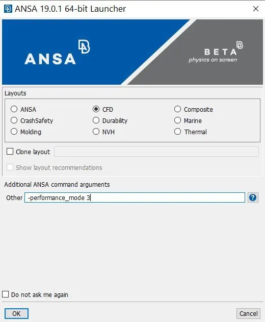
CFD contains a lot of solvers those poses a unique challenges for pre-processing and post-processing.By selecting the layout will helps to improve accuracy for the simulation Results.Additional ANSA Command arguments are the launcher options -performance_mode 3-Adjust the drawing performance and the memory usage.This option will slower the drawing performance for ehancing the quality.
2.The ANSA-CFD window opens then Open the file using File->Open option.Open window appears to select the file,After selecting and clicking the open button.Model Displays on the window.
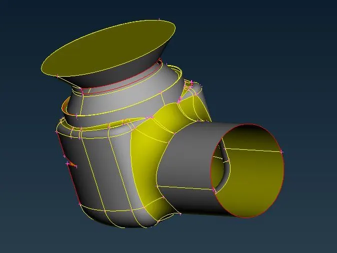
3.The loaded geometry has a Single CONS means that surfaces are missing,to patch with the help of creating a new surface.This would be done by Topo Module->faces->New
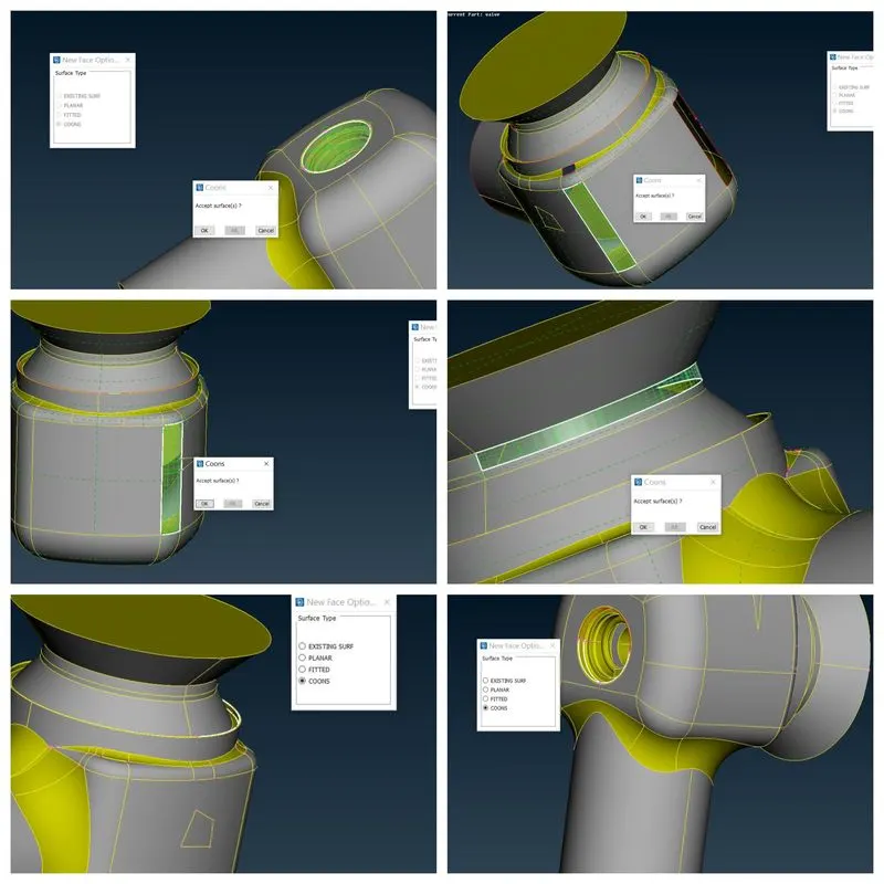
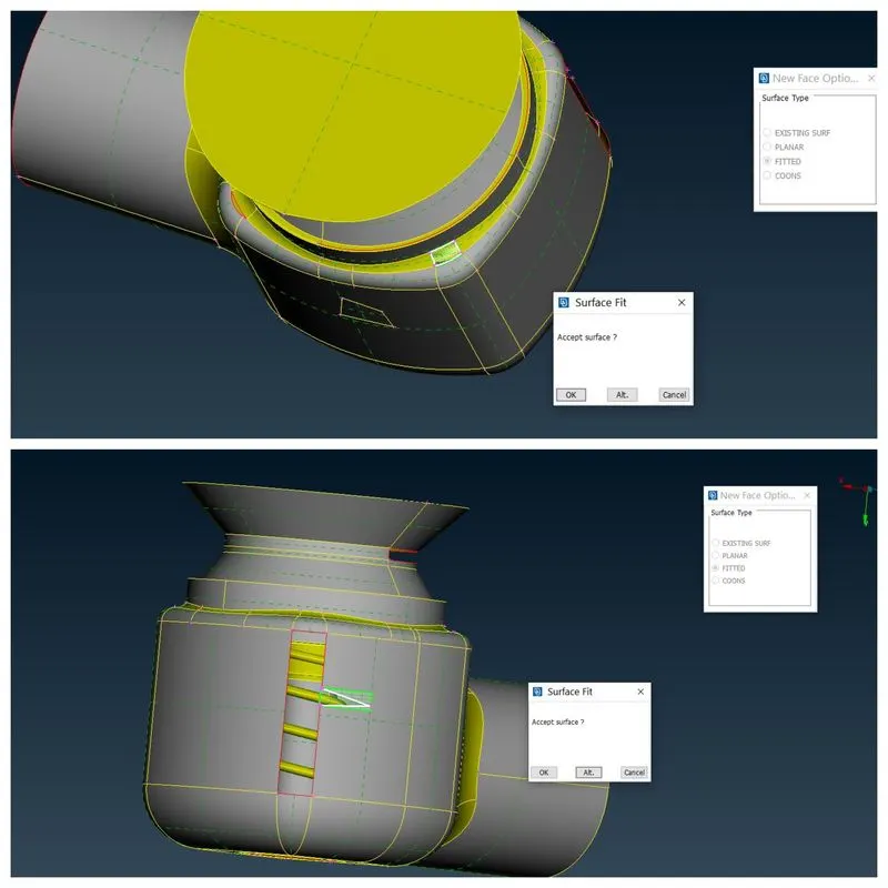
New face options window appears - provides a four different algorithms for creating a new faces (i) COONS-This model takes the boundaries as inputs as three or four,if three boundaries presented as a input and fourth boundary will be automatically created as a straight line or similar to the opposite boundary.The face created by the COONS Interpolation pricipal.This function creates multipatch face(ii)Existing Surf-this function defines a new Face laying on an existing surface.(iii)Planar-This function defines a new planar face. The underlying surface is automatically created.(iv)Fitted-The FITTED option is used for the definition of a non-planar Face. The created Face fits to the selected boundaries.From that Existing surf has been used.Existing surf has used to create and join the surface of the missing surface depicted in the below picture.
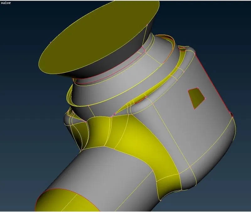
Single CONS has been selected using loop button and then scrolling button clicked.Selected the face by enabling the cross hatch option on the facesDraw toolbar.(i)Loop button-it is used select the CONS by one click that is connect as a chain.(ii)Crosshatch is used to select the faces.
4.COONS(reason for selecting the COONS is that boundaries show not as a planar and depends on one surface and fitted creates with alternatives ) is selected for six different boundaries.After selecting COONS on new face options,selected a boundary by one click with help of loop option and scrolling button is clicked.Top left side shown in the image below,creation of face there after the geometry checking for errors.
5.Topo Module->faces->new is selected,new face options window appears from that fitted is selected and the boundaries selected using entity option.sutface fit window appears,ok button is selected to accept the surface.This will be used for two boundaries.
6.Created a new face using fill hole ,Topo->CONS->Fill Hole is selected.After selecting that,Fill hole parameters window appears then clicked on CONS but it selects the whole chain and then pressed ok.

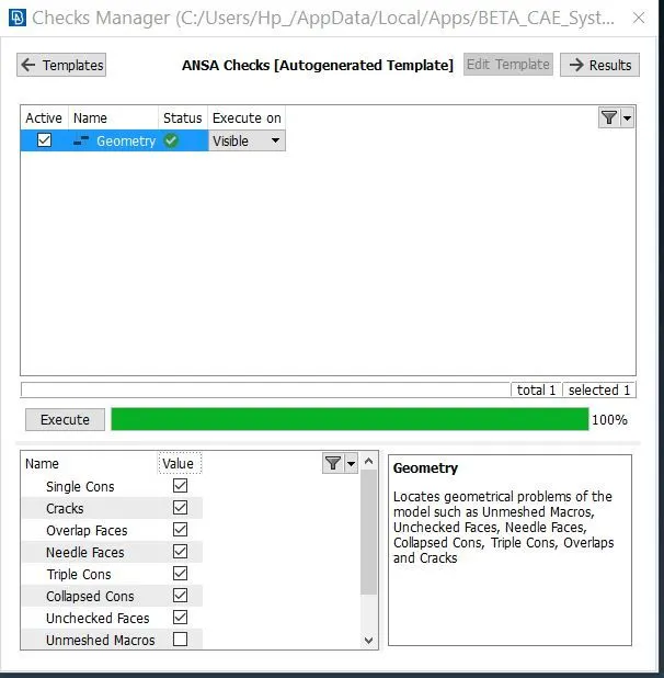
7.For checking the geometry with errors,on the Tools selected the checks option,under that geometry option is selected and then executed.(To determine the errors present in the geometry).
8.picture attached above for COONS algorithm show on the top left side creates a new face using describe procedure at point 4.
9.For meshing,presence of small faces needs that mesh to fit in that face.Due to the big component ,small mesh leads to creation of more elements.Solver needs a lot of computational resources and time .To avoid that deleting the small faces with the Cut option using Topo Module->faces->Cut. Selected the CONS and then right clicked to merge the cutted faces.Orange lines indicates the history partitioned face CONS (Deleted partioning the face CONS)
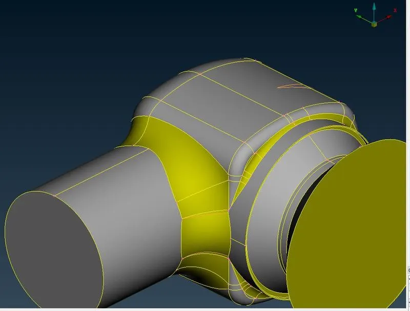
Cut option-Using this option ,split the one surface into two or more surfaces by using CONS and this can used to reduce the surface from two or more to one by deselecting the CONS
10.Creating a each and every PID (Represents Property IDs) by repeating the procedure that is starts by selecting properties on the Lists Toolbar.right-clicked new has selected it shows shell property and left-clicked to select it and provided a names on the Property window and clicked ok button.so the names are assigned as inlet,outlet,body,base surface,valve head,column,spring to the each of the Created PIDS.
PIDS-It represents the region of the model
11.Assigning the region to the PIDs ,starts by the right click on the property window and then select apply option and then the region is selected using cross-hatch(or)PID region(or)box-select and then scroll button is clicked and repeating this procedure for each of the PID created.
PID Region-By default ,whole model is assigned to the one PID.By selecting the surface it will select all the connected suraface that is under one PID
Cross Hatch-green lines will be displayed.to select the surface those lines has to select
Entities -It can be used to select the surface by clicking the CONS
box-select-Left click and dragging over the surface will select the surface.Hiding unrelated surface by using OR or Not on the focus toolbar
PID-Region of PID by selecting simple left -click at the green-lines or at CONS.
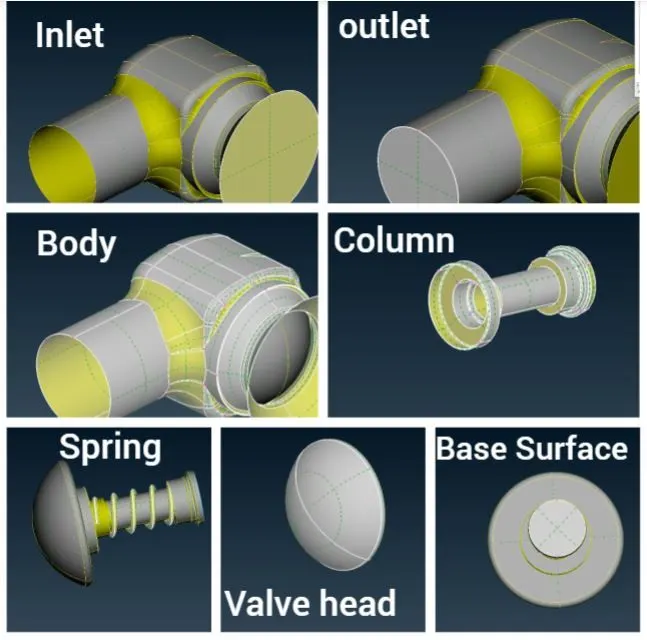
12.On the default PID consists only a deleted faces information.we can't able to delete this PID.To delete that PID.Topo module->faces->Undelete option will provides the deleted faces.then one surface is selected and middle scroll button is clicked.on the properties window the Default pid consist of deleted faces.then right clicked the default PID and choosed the delete option.to avoid the overlap faces.
Undelete Option-This function recovers a Face that was previously deleted, provided that the COMPRESS command was not used since the Face was deleted
13.File saved by using file-> save option.(for all mesh length upto the previous step is common to avoid repeating all those steps file is saved ,after this meshing would be done and then save as command will be used to save as the separate file for different target length)
14.Before starting the mesh,the procedure describe for meshing would be repeated for 3 different target lengths.Meshing procedure starts by changing the module to the mesh.Then length option under the Perimeter is selected.Selection window appears perimeter is selected then region would be selected using box select and scroll button is clicked and length parameters window will appear then enter the length value and then ok button is pressed and then macros is selected and then region will be selected using box select and then length parameters window will appear then enter the value and the press ok button.
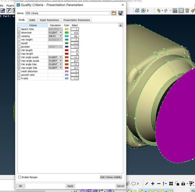
Perimeters and Macros-Perimeters is length between the nodes on segments and element length described for macro areas
15.Mesh Parameters from the utilities toolbar will open the mesh parameter window and them enter the value of target length and maximum and minimum target length value entered by using below formula and then ok button pressed.
Maximum target length=Target length+0.5;
Minimum target length=Target length-0.5;
Target length- Target Length defines the element length used by the functions that modify,create mesh.
16.Quality Criteria selected from utilities toolbar,quality criteria -presentation parameters window appeared value for max and min length is provided and ok button is selected.
17.Mesh generation ->SpotMesh is selected and regions can be selected using PID from the property window and right clicked then show only option is clicked and then spotmesh->visible is selected .Meshing only for selected PID would carried out.In the similar way for all other PIDs are meshed and finally right-clicked PID and show is selcted for each and every PID.Total mesh will be displayed.
18.File->save option is used and save window appears .provide the name for the file and pressed the save button.
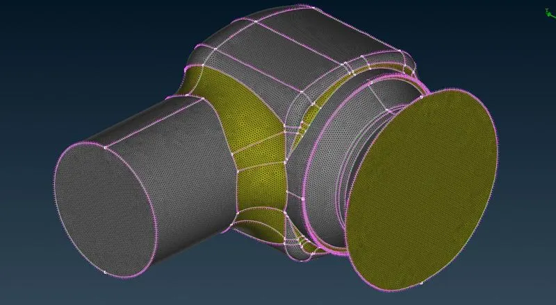
target length-1 mm
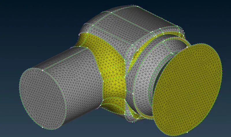
target length-3 mm
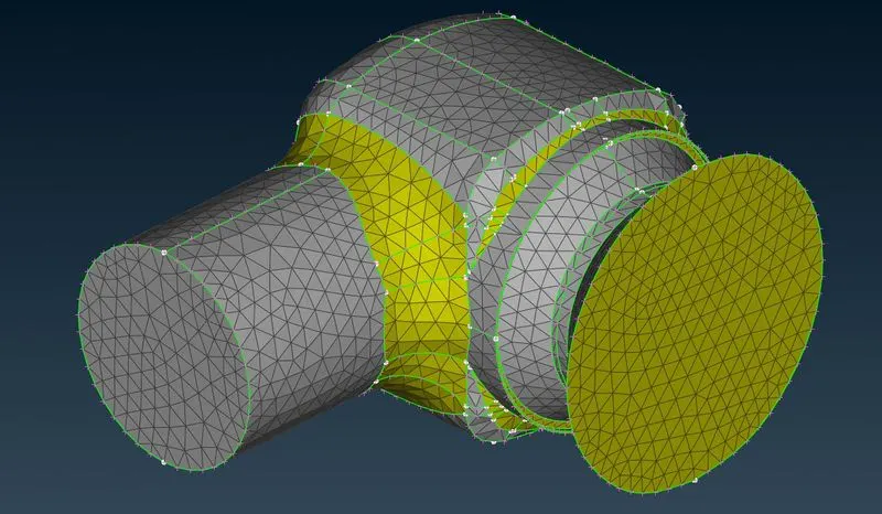
target length-5 mm
Meshing Result:
|
S.no |
Target length |
Elements |
|
1. |
1 mm |
211768 |
|
2. |
3 mm |
21086 |
|
3. |
5 mm |
6934 |
Conclusion:
1.3.5 mm cross-section length on the spring.If the target length is about 3 mm it creates one element.To provide a better quality atleast 2 elements has to fit inside.At 3 and 5 mm target length due to that,there is mesh distortion for spring and valve head
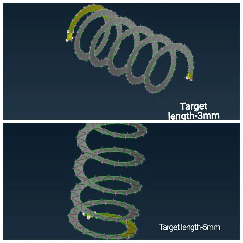
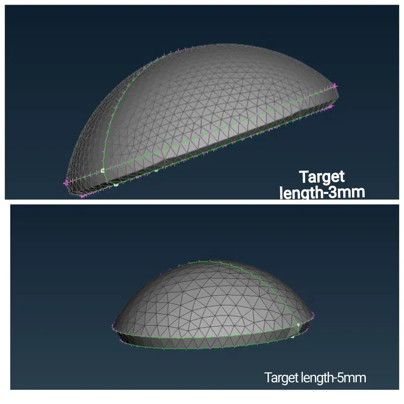
2.Based upon the 3 and 5 mm target length,mesh should alter for the spring and valvehead to the 1 mm target length for both cases to yield the better results.
3.1 mm mesh for valvehead and spring used for the cases of 3 and 5 mm target length for the whole model.No of elements are created are 67474 and 44942.This is done for mesh to fit in every small surface.
4.As reducing the value of target length,no of elements increases ,it represents the refining of mesh.
5.Geometry cleanup has performed and checked for errors.
6.Surface Meshing can be created on the valve for three different target lengths using triangular element type.
7.1 mm target length is showing good results because the shape of the meshing is smooth and no distortion of the meshed body shape where the elements is high
Files:
Mesh files attached here in a Zip Format, https://drive.google.com/file/d/1GvX0PwCLZgeIO9BPs4aadaSfOz4098dG/view?usp=drive_link