Week 2 Challenge : Surface meshing on a Pressure valve
Aim: To perform Surface Meshing on a Pressure Valve.
Theory:
Setup:
- Importing geometry into the GUI of ANSA.
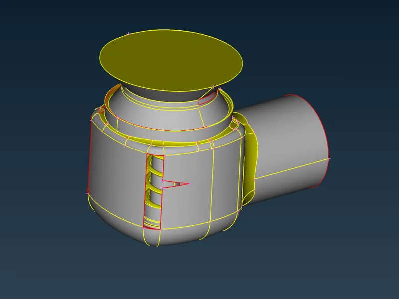
- Perform Geometry checks.
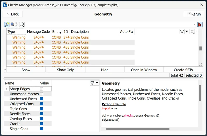
- Geometry Cleanup:
Single CONS are the main errors to be solved. Single CONS implies that there is a surface missing i.e.: a CONS is shared by only 1 surface instead of atleast 2 surfaces.
So, wherever there is a Single CONS we have to create a surface and therfore converting it into a double CONS. The 'NEW' option under the heading 'FACES' is used to do so.
There are few more options under 'NEW FACES' to choose from namely, Existing Surface, Planar, Fitted and COONS. Each of these options represents an algorithm to create a particular kind of surface based on the relationship with the boundary points of the surface formed.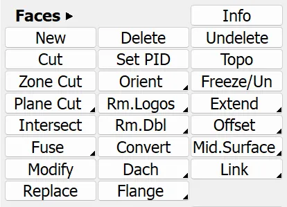
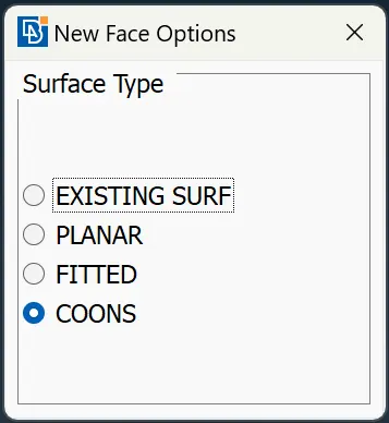
Existing Surf: It is used to patch a surface by taking inputs as the Single CONS' and an Existing surface to match the new surface with. Like the one used to patch the trapezium shaped hole.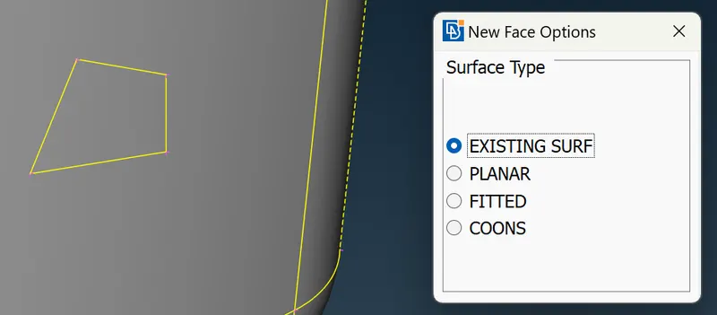
Planar: It is generally used to patch a planar hole i.e.: one that is without a curvature. Like the inlet and outlet holes. 'FILL HOLE' option can also be used.
Fitted: Surfaces are created by fitting a mathematical surface to a set of given curves or boundary edges. The surface is adjusted to pass through the given curves or edges as closely as possible, while also minimizing any deviations or distortions. Fitted surfaces are typically smoother and more accurate than COONS surfaces, but can be more computationally expensive to generate.
COONS: COONS are created by interpolating between the given curves or boundary edges. The surface is generated by connecting adjacent edges with straight or curved lines, and then filling in the resulting grid with flat or smoothly curved patches. COONS surfaces are typically faster to generate than fitted surfaces, but may have more noticeable distortions or inaccuracies.
If the surface obtained using any particular methods doesn't give desired result, 'UNIVERSAL DELETE' option can be used and any other method can be used for creating the surface until the desired surface is obtained.
Few problems encountered were solved by following certain practices like:- If 2 single loops are there and vertical face is to be created avoid loop selection rather go for entity selection.
- Selection of equal length CONS is must.
- Cracks can be generated if proper selection is not done while creating the faces. Should select all boundaries available.
- Small surfaces should be removed as they will interfere negatively with the meshing operation. As it will restrict size of element that can fit there. This is done by choosing CUT option and Right Clicking the unwanted CONS'.
- Also since the analysis is CFD type analysis the geometry should be closed.
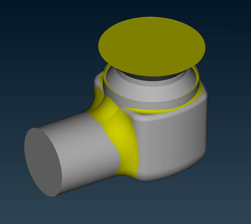
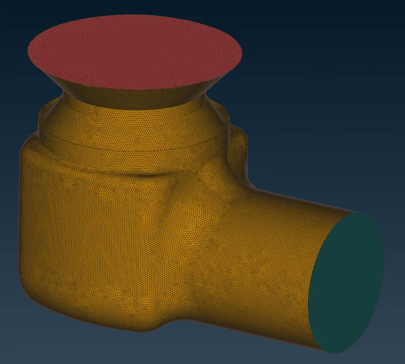
- Naming different parts of geometry
PID (Property ID) Manager is used to label different parts of the geometry. For the case at hand. Boolean operations are used to show/hide surfaces. Also to view the PIDs we have to switch the draw mode to PID.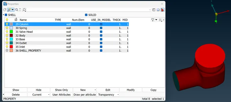
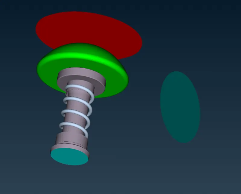
- Meshing: Meshing length is the perimeter for mesh size. It is to be provided at 4 places- Perimeter, Macro, Mesh parameters and Mesh Quality.
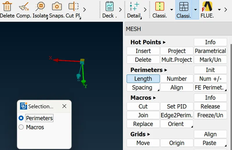
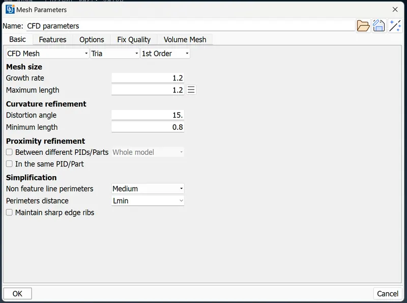
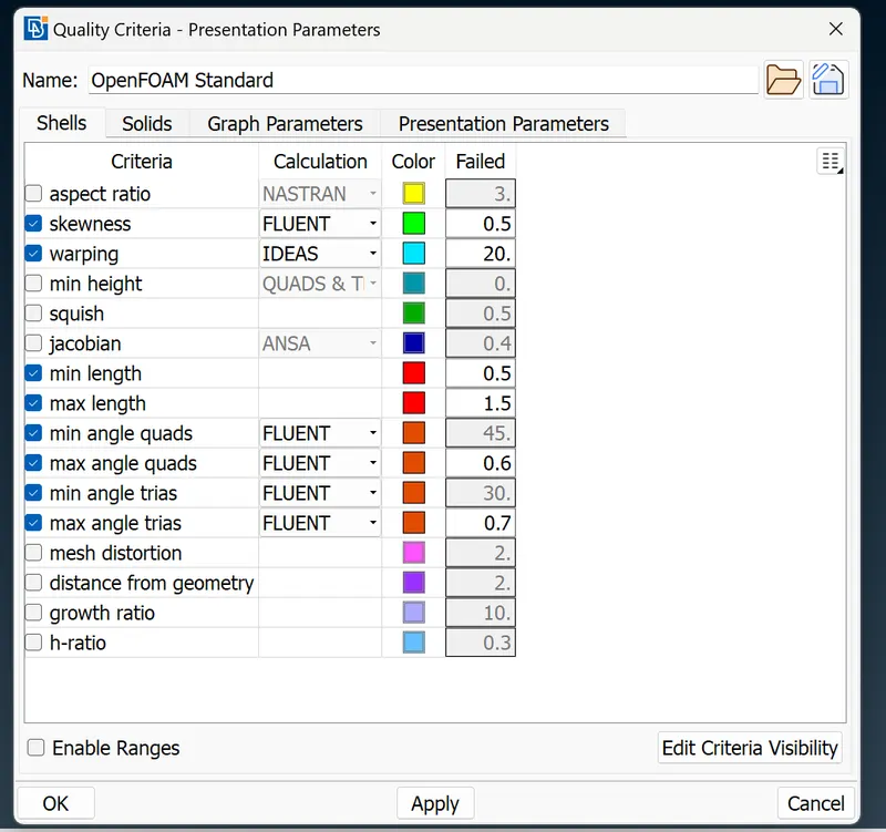
Perimeter is for the CONS while Macros is for the Surface formed by these CONS'.
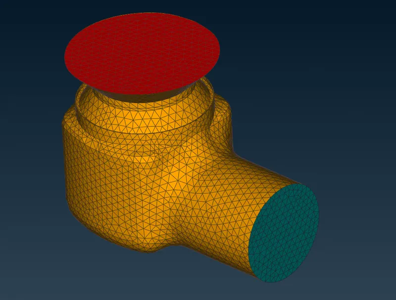
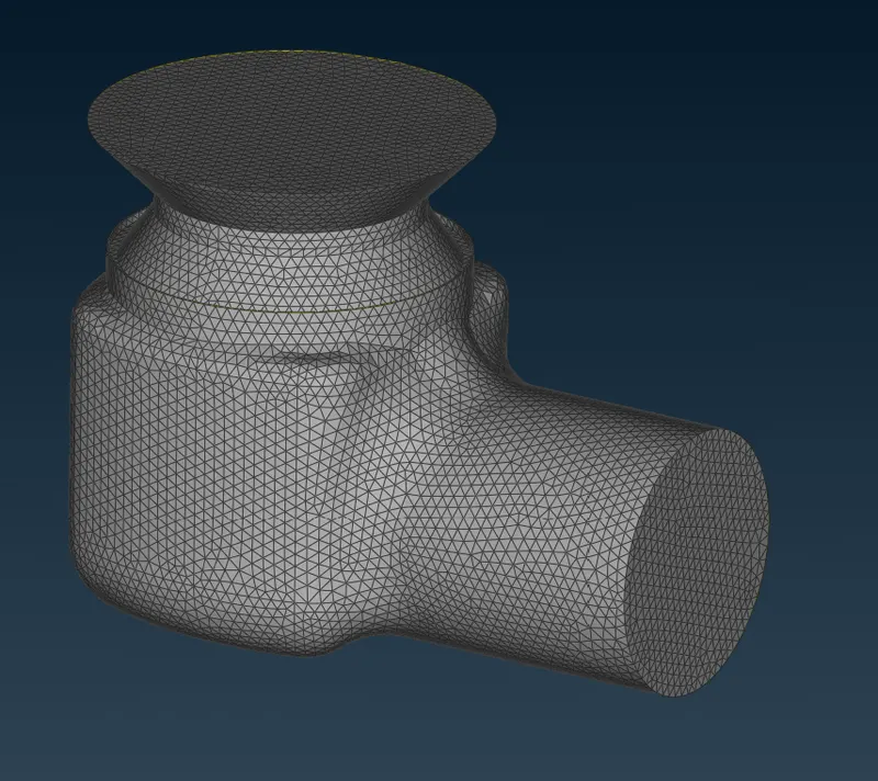
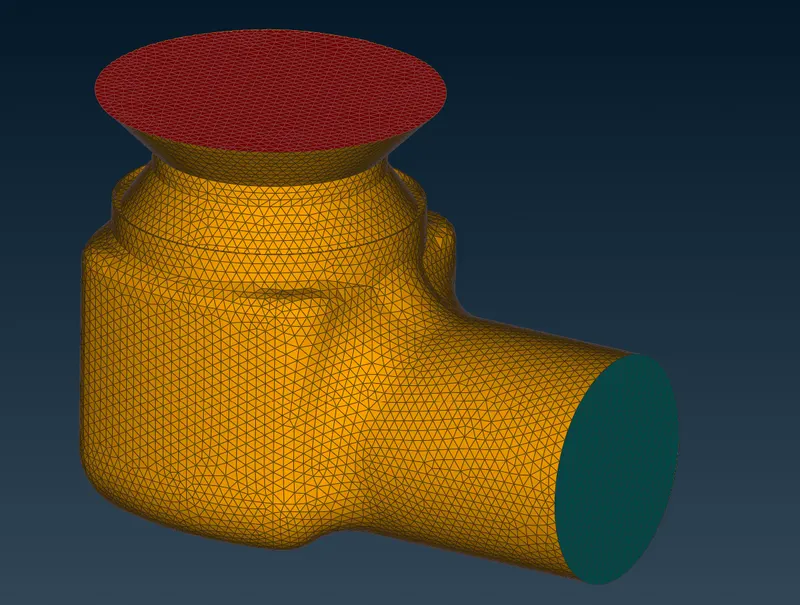
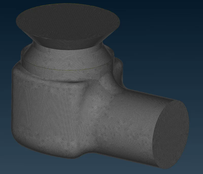
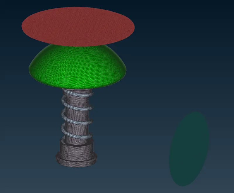
The mesh algorithm selected for meshing is CFD mesh. The Meshing was done for 3 element sizes- 5mm, 3mm and 1 mm.
The elment shape was kept as TRIA (Triangular). - Results:
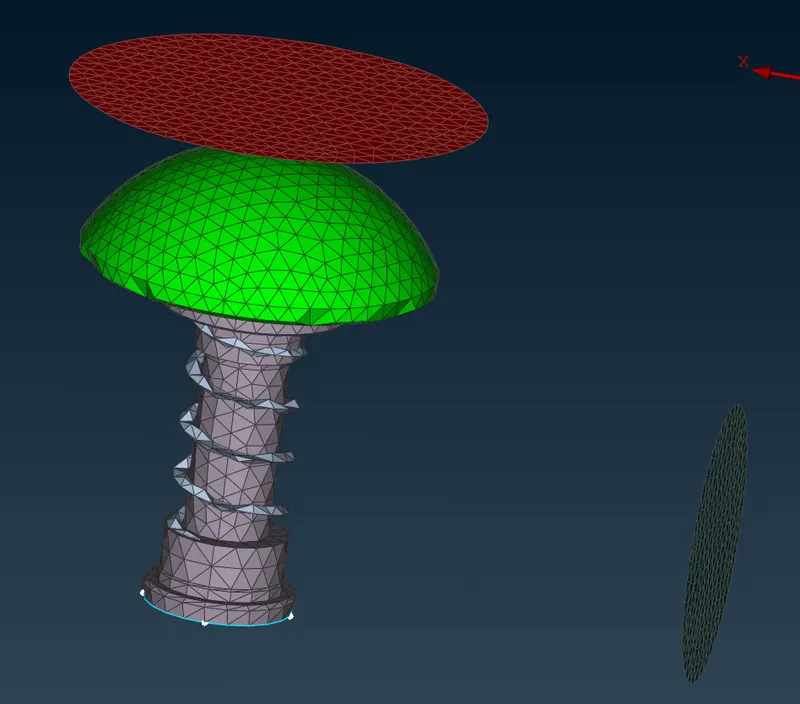
Following mesh was obtained for all 3 cases:- 5 mm mesh sizes.
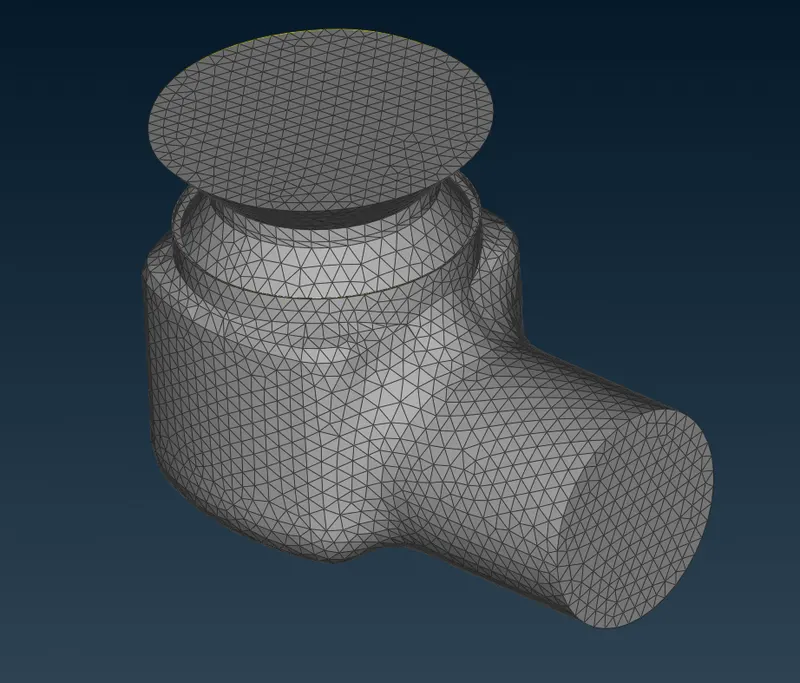
- 3 mm mesh size.
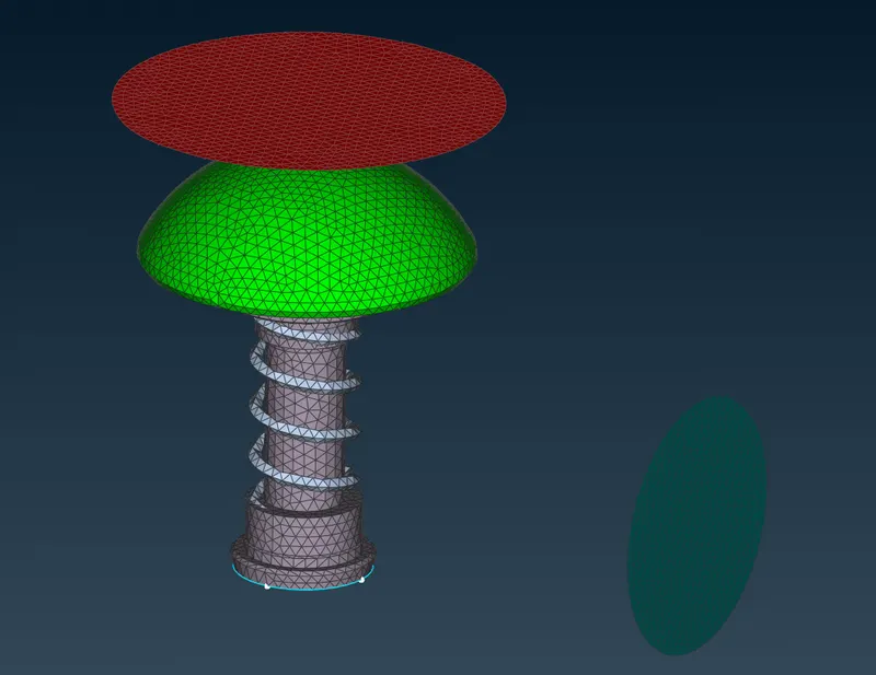
- 1 mm mesh size.
Mesh Size Cell Count 5 mm 26110 3 mm 35532 1 mm 218800
- 5 mm mesh sizes.
- Conclusion:
- The mesh obtained using 5mm element size is coarser then other 2 cases. The surfaces of parts like spring and the curved faces aren't captured properly.
- The mesh obtained from 3 mm mesh size is little finer and better than 5mm case but, it still isn't able to capture the curvature of the valve head properly and also the spring diameter is of the order of element size so that as well isn't captured properly. Rest of the geometry looks fine.
- The mesh obtained from 1 mm mesh size is the finest and captures the valve head and spring geometry properly. So, overall this would be the best mesh of all 3 but, the cell count is huge. As seen from above table, the mesh count for 1 mm is greater than that of 5 mm mesh by a factor of almost 10. So, the computational resources required to create such a mesh and hence to solve the physics over such a mesh will be high.
- Ideal mesh should be the one that is fine at places to capture the geometry features like curves properly and also coarse at places away from curved faces and of lesser interests. For eg. In above case the mesh in the middle of valve head away from the CONS, where curvature is not that high, the mesh can be coarser than the region near the CONS. This can be done by having different mesh length values for Perimeter and Macros. The Perimeter-value should be lower than the Macro-value.