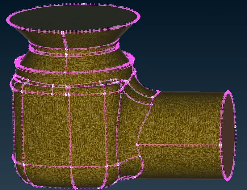
Week 2 Challenge : Surface meshing on a Pressure valve
Surface meshing on a Pressure valve
Aim: Check the geometrical errors on the pressure valve and perform topology cleanup. Meshing it for three target lengths.
Objectives: Mesh it for target lengths 1mm, 3mm, and 5mm.
Procedure:
- First, observe the geometry and get familiar with it. Note down any errors.
- Using checks from the tools bar, find out all the errors present in the geometry.
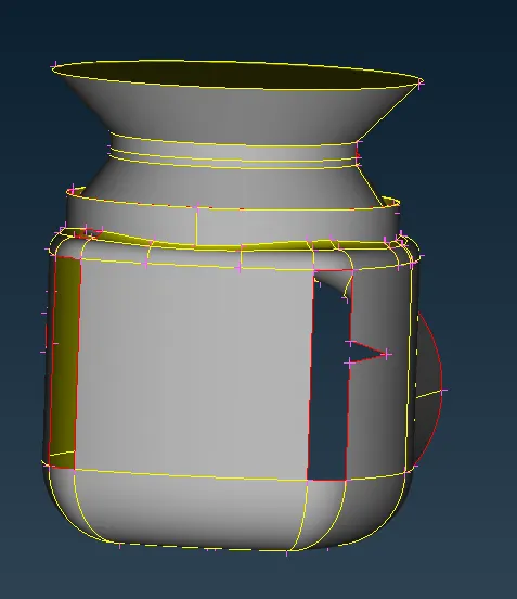
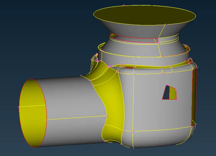
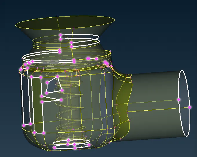
- As we can see in the image, the highlighted entities are geometrical errors found in the geometry, which are single cons.
- Using the fill hole, new from faces group, and various options clean the errors by creating new entities for the single cons.
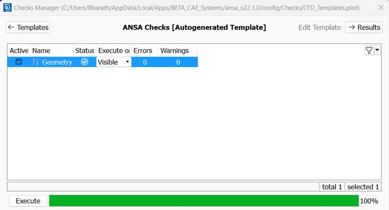
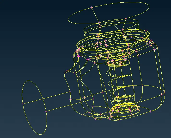
- In CFD analysis, the model should be closed without any openings, here we are closing all the openings. This will create triple cons which are acceptable and can be ignored.
- check for any macros which are very small and could cause a problem for meshing, while the meshing length is smaller than the macro, using a cut function from the faces group clears those cons.
- The next step is to assign the PIDs to various entities.
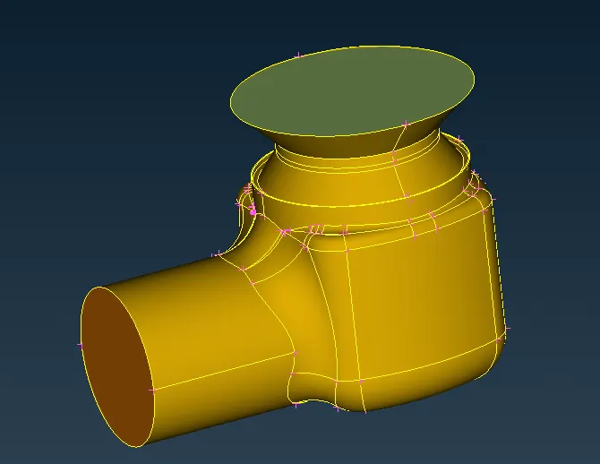
- For meshing, go to mesh utilities and set the minimum and maximum target lengths as well as the element type.
- Then go to the mesh module and set the perimeter and macro length with the target length.
- Using the mesh group, select spot mesh and select the entities to mesh.
- Verify if all macros have meshed.
Conclusion:
The pressure valve is meshed for 3 target lengths.
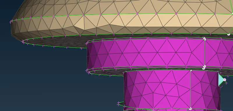
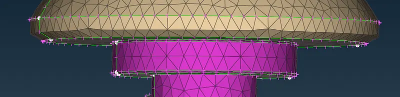
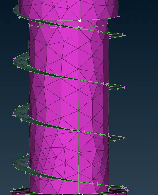
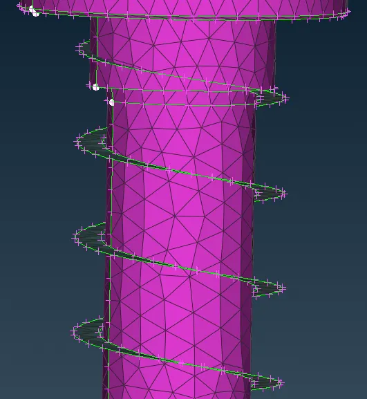
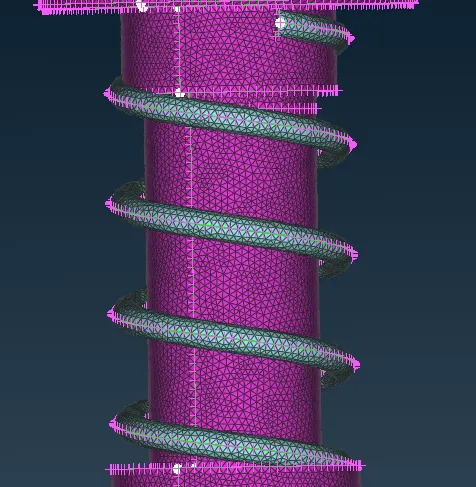
Looking at the mesh for the pressure valve head and spring we can observe the mesh capturing the CAD features.
In all three cases, 1mm is giving a good result than the other 2 cases. The valve head surfaces are captured well and the spring is also meshed properly compared to the other 2 cases
| 5mm | 3mm | 1mm |
 |
 |
 |
 |
 |
 |