Week 2 Challenge : Surface meshing on a Pressure valve
Surface meshing on a Pressure valve :
Aim
To perform a surface mesh on a given model(Pressure valve)
Objectives:
* To check for the geometrical errors and perform Topology cleanup.
* To Set different target lengths as different cases and mesh the model.
Introduction :
Procedure :
For solving we follow the below procedure ,
* Import the CAD model.
* Geometry check-up.
* Topo/Geometry cleanup.
* Creating a relevant PIDs and defining it.
* Defining the element size or length.
* Selection of Meshing type.
* Generating Mesh.
Importing a CAD model :
* To import the CAD model,
Go to file -> open -> browse the location of the CAD model -> select it click on open.
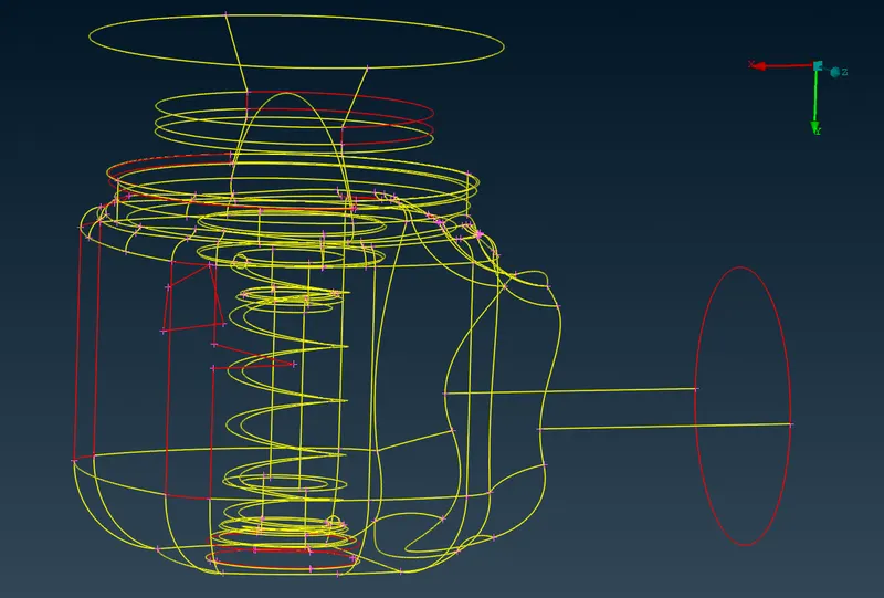
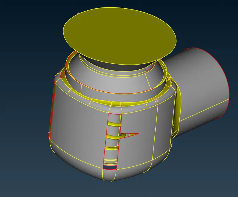
In this wireframe of the model given, we can see a lot of topological errors ,but before doing topo clean up let us perform geometry check to see all the errors in the given model.
Geometry check-up :
Geometry check up is done to check errors in the model like unclosed faces, single cons and so on and some of the errors are shown on above figure .
To do this operation , go to toolbar -> checks -> geometry -> visible -> execute .
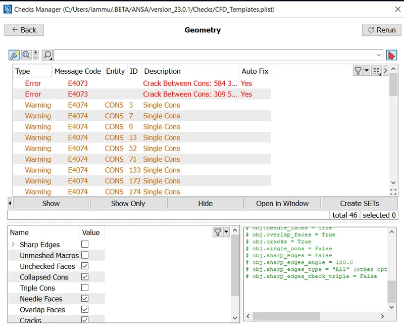
From the above figure we can see a lot of errors after geometry check up.
In those errors if you see there are lot of single cons to be resolved .
As single cons will be present when there are open surfaces or cons that share edge with only one surface ,as this is 3D
geometry for CFD applications we need closed surfaces to do volumetric mesh and we need to fix single cons.
Topo/Geometry cleanup :
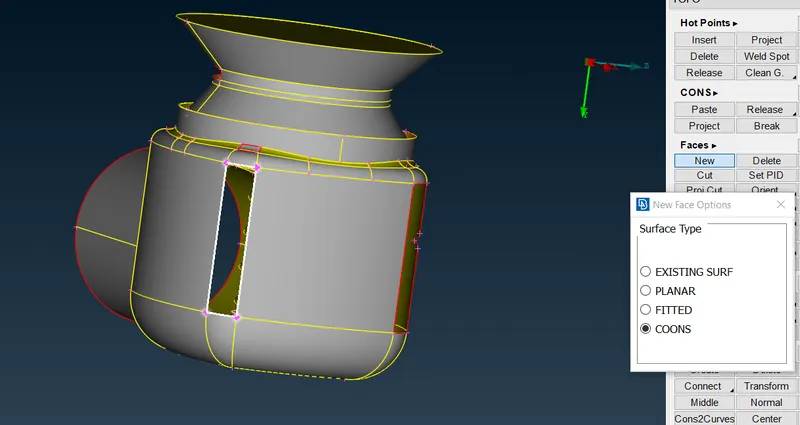
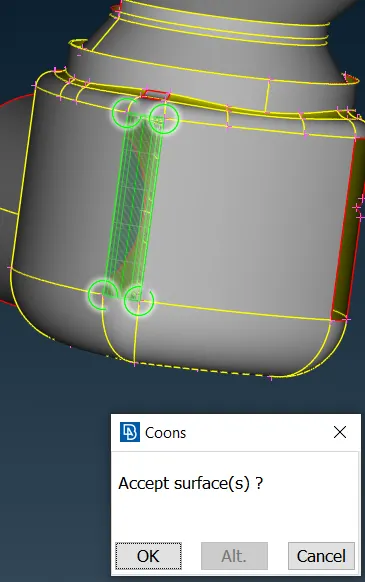
* We will patch all the single cons by creating a new face over there .
* We will create / patch the surface by using the new under faces .
* Here we have 4 options to use under new tab , they are existing surface ,planar, coons and fitted.
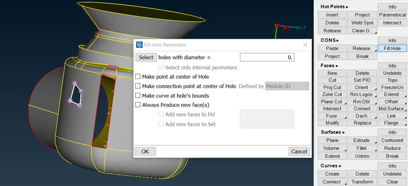
We will also use fill holes under cons. when fill hole is used surfaces created won't appear as a patch on it.
* We use these different type of options to create face depending upon the applications .
So when one fails to create a better surface , we try with another.
Creating a relevant PIDs and defining it :
In order to create new PID , right click on properties manager -> click new -> then select shell property -> then again select shell property -> then give name in the popup box -> then ok .
* In the similar way create PID for Column, Column head, Spring, Body.
* Then next thing is assign these PID's to the components of the geometry .
* To apply , we select /click on the PID to apply in the PID manager -> then right click on it -> then click on apply -> then in the geometry select the cross hatch of the surface you want to assign -> then middle click . In the similar way we have to apply PID's we have created . To give the PID we select with the different type of selection available to select the exact surface needed.
* Then after assigning the PID , delete the empty orginal PID which has no components assigned by using compress. 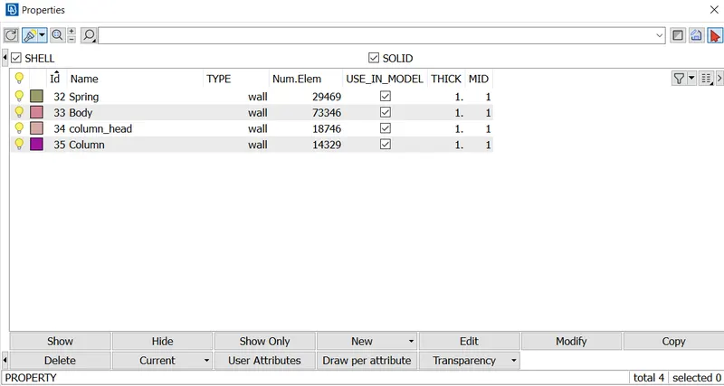
Defining the element size/length :
* Here we have three different target lengths as three different cases and we have to mesh the model with all three different lengths.
Target length = 1mm, 3 mm and 5 mm (i.e. 3 cases).
Let's first mesh with three different sizes and then finally conclude by comparing the results of all the three cases.
* We have to give the mesh length .
1) under perimeters we give length as 1mm 2) under macros we give length as 1mm.
Go to mesh utility -> perimeters tab -> length -> now select perimeters and then-> click left mouse button and drag and select the entire model -> click middle mouse button -> Enter the element length as 1 mm -> Click middle mouse button.
In the similar way select macros instead of perimeters under length and give mesh length as 1 mm.
To create a CFD mesh, using Auto CFD option will bring us better mesh in which can provide some kind of quality parameters to the mesh we create, like we can give max and min mesh size , which in turn we may have better quality mesh which are created with limits for target length 1mm, 3mm, 5mm I have given limits 0.5-1.5, 2.5-3.5, 4.5-5.5.
This can be created by following steps, Click on Spacing tab under length tab in perimeter and we specify the max and min limits before doing a mesh.
Selecting mesh type & generating mesh :
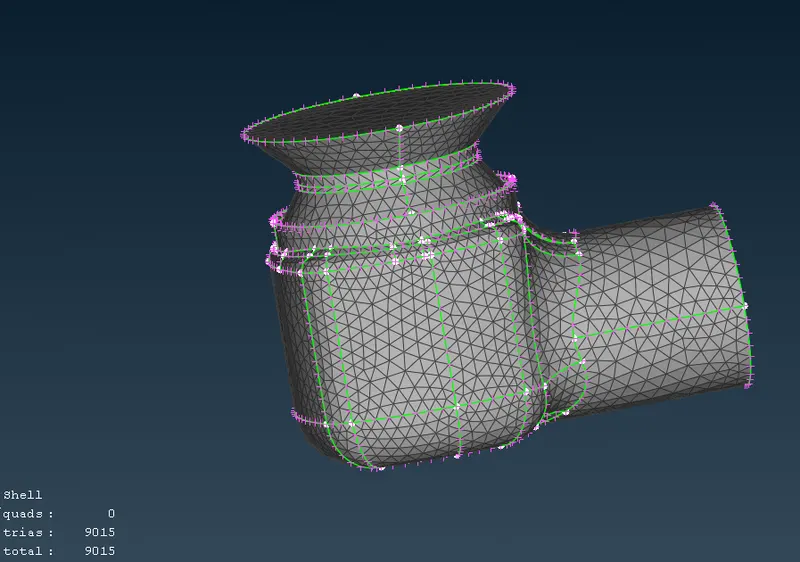
Go to Mesh Generation -> spot Mesh -> tria -> CFD Mesh -> drag and select the entire model -> click on the scroll button/ middle mouse button on mouse to mesh (or) we can directly select visible under drop down menu of CFD mesh instead of drag and select the entire model. We have done this for all three target lengths and the differences can viewed with figure below.
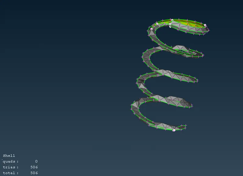
* Target length = 5mm :
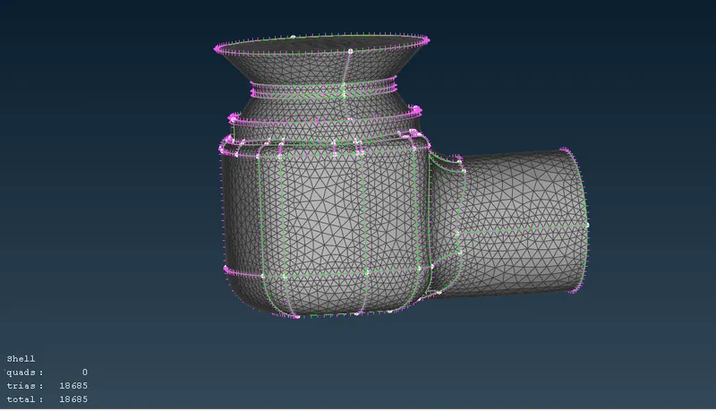
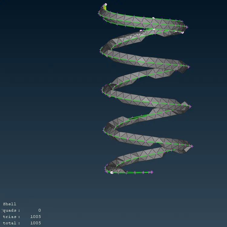
* Target length = 3mm :
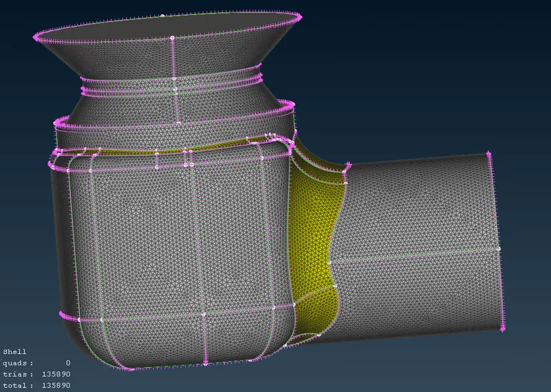
* Target length = 1mm :
Conclusion :
Here finally we have a surface mesh to the given model - pressure valve with three different lengths i.e., 1mm, 3 mm, 5mm.
We can observe that as, with increase in mesh size there is a decrease in the number of elements .
In 1mm mesh length, the size of the elements is small when compared to others, we have more number of elements (around 135000) , which in turn makes the mesh to capture the geometry very well as the surface quality also very good.
When the target length is increased to 3 mm then we have less number of elements (around 19000) than the previous case, the capturing of the geometry is not as good as previous case .The surface quality of mesh size 3mm is less when compared mesh size 1mm.
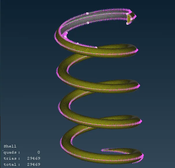
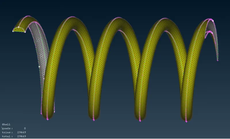
When the target length is increased to 5 mm then we have very less number of elements (around 9000) when compared to previous cases .The surface capture by mesh is also worst .
For mesh ,we can see in the spring there is failure of mesh , the spring shape is totally lost .This happened because, if we have very small surface and if that surface is meshed with a target length greater than than the size of the surface then obviously failure of mesh takes place and the surface mesh can't be captured with a good quality.
The size of the target length shoud be made considering the smallest component of the given model.
So if our target length is small, we have large number of mesh that captures the surface, then we will have a good quality mesh, and so our geometry is very well captured and surface quality is very good.
In this challenge, with the mesh sizes given 1mm, 3mm, 5mm. when compared between these we get well captured and good quality mesh is found with the target length 1mm. So hence conclude that 1mm mesh size is better when compared to others.
* Attached mesh file's link - https://drive.google.com/file/d/1IeMa1HsCFFra9G1kLNIShNhFNvs6VJTd/view?usp=share_link