Week 2 Challenge : Surface meshing on a Pressure valve
Surface meshing on a Pressure valve
A pressure Relief Valve is a safety device designed to protect a pressurized vessel or system during an overpressure event. The primary purpose of a pressure Relief Valve is protection of life and property by venting fluid from an overpressurized vessel. Pressure valves are widely used in all types neumatic, hydraulics, boilers , cars & areoplanes etc, it is a nescessary safety eqipment. Pressure valves releases extra extra pressure generated inside a system by opening valves as required, sensors are inbuilt along with pressure valves which gives signals when abnormal increase in pressure is detected and then valves of pressure valve opens up to release extra pressure and brings back pressure inside system to normal levels.
Objective-
- Main objective of this project is to mesh a pressure valve with 3mm , 5mm & 1mm mesh size.
- Observe geometry changes with all three mesh sizes.
- Apply PIDs to assign & differentiate between regions on geometry (ie inlet , outlet, etc)
- Get yourself familiar with boolean operations in ANSA.
- Submit a detailed report of your project and step by step explainations.
Geometry
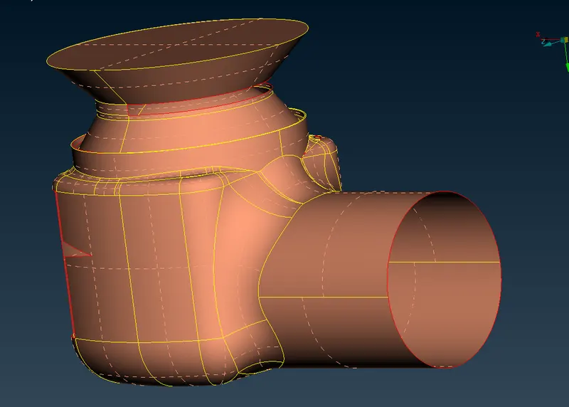
This is the original geometry which is downloaded from challenge page, as you can see there are lots of open areas on surface. Yellow color line represents double cons and red color lines represents single cons.
single cons are not allowed in the geometry and need to be fixed.
Always before working on choose place your figure into PID mode and after that start working on it.
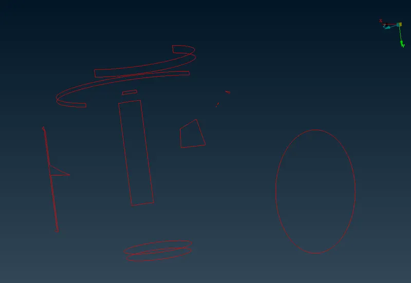
- To take a proper look at single cons use wire frame mode, turn on wire frame mode and then choose single cons and turn of double cons. Below is the proper view of single cons using wire frame mode and all those cons need to converted to double cons.
- Use new tool from surface tools to create new faces and fill holes in geometry.
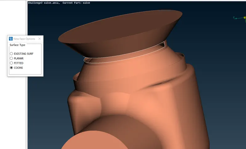
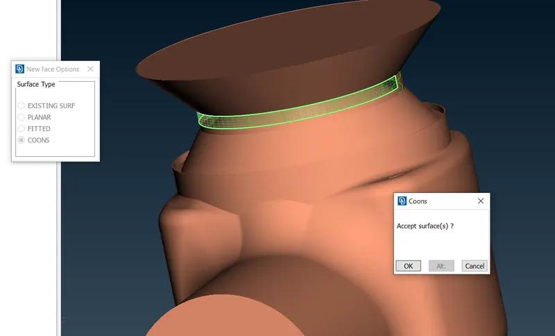
Creating new surface using face tool
- choose new from surface tool
- click on single cons cons and do middle click , new surface is created.
- There are 4 options in new tool under surface tool category and we have used all those tool to patch our diiferent single cons.
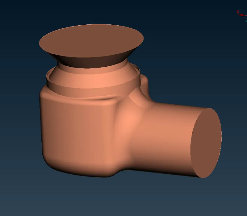
Geometry after surfacing
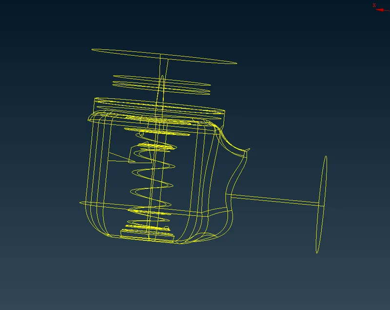
Below is the geomerty after surfacing, to check if there is any single cons left use wire frame mode and turn on both single and double con option. As you can see in secong figure there is only yellow lines representing in wire frame mode and no red lines this means that all our red cons are gone and geometry is properly fixed.
PID regions-
Next step after geometry cleanup is to assign regions. Geometry is consisted of diiferents and each parts is required to have unique PID
Steps to assign PIDs
- Choose property box from top and create new PID regions and give names to them, next step is to give PIDs created to be assigned to regions on geometry.
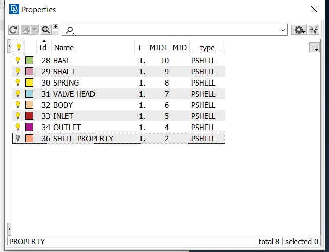
- choose PID and then do right click , dialogue box will appear and click apply and choose region on boundary and then do middle click. PID to that region is assigned.
- We can use entity option or PId option to select a single phase or group of phases from geomerty.
- After assigning region to outer surface hide those surace either by using boolean opration tools or by simply turning of yellow bulbs you can see in property box.
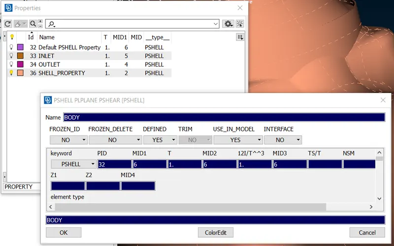
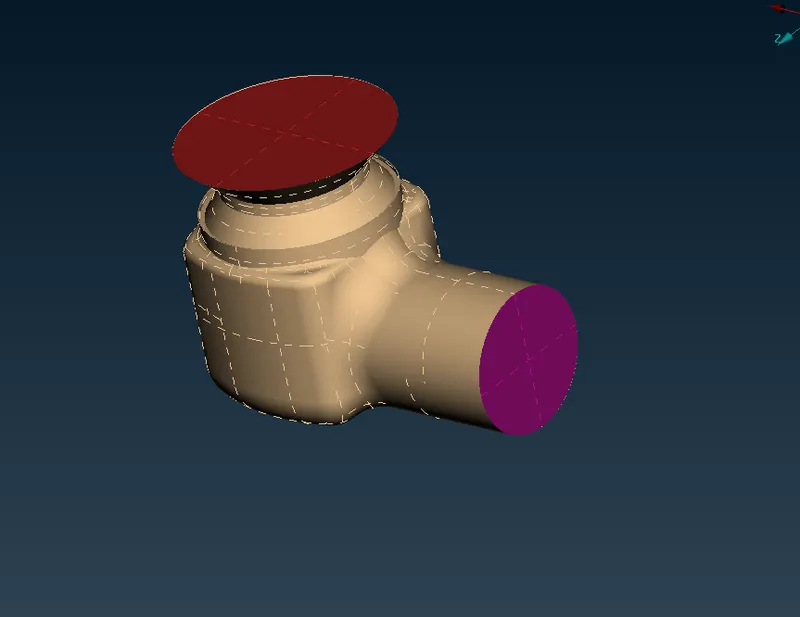
- PID to outer body is assigned and then hide outer body so that we can work on inside body.
- After hiding outer body PIds to inner body is assigned and so with this all regions are assigned with their unique PIDs. Next step is meshing all regions
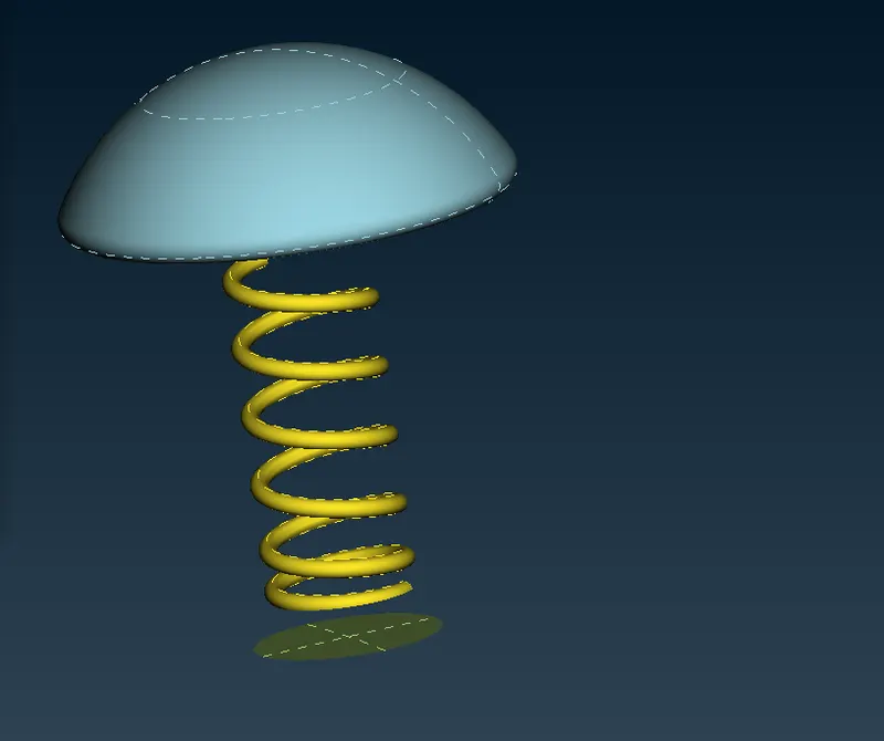
Meshing of Geometry-
Steps for meshing
- Shift from topo mode to mesh mode
- choose length from Perimeters
- we will mesh with three mesh size 5mm, 3mm and 1mm
- After choose choosing length a dialogue box will appear which will ask you to give inputs in perimeter and macros
- Do right click and drag your cursor and choose whole geometry , dialogue box will appear asking you to give mesh length, give mesh lenght and click ok
- Repeat same process with macros
- click on mesh parameter icon and choose element type as tria , give mesh length and choose max and min length for your mesh click ok
- Go to quality parameter and give min and max mesh length and then click ok.
Mesh size 5mm
Meshing with 5mm grid size does not give a finer look and distorts original geometry.
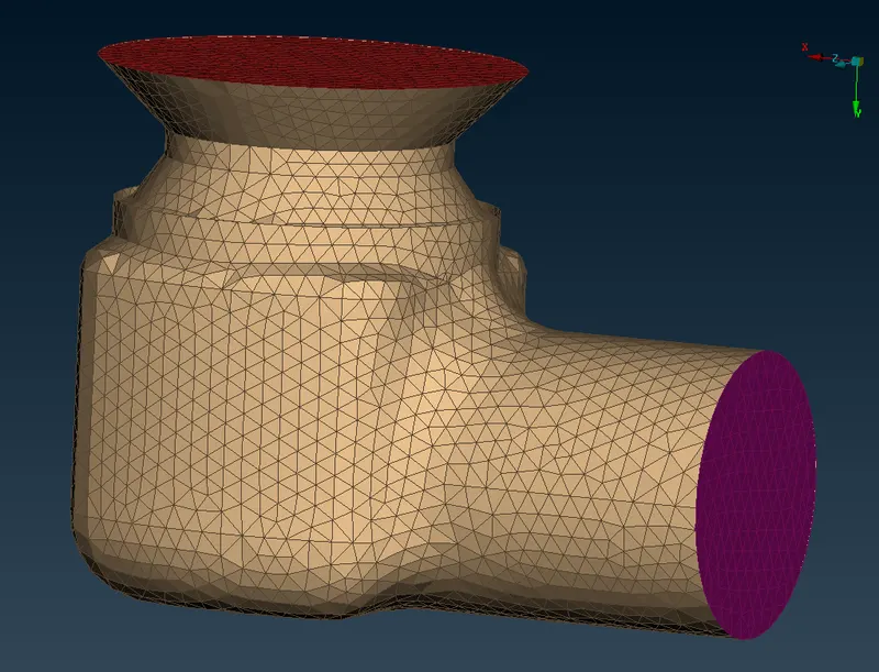
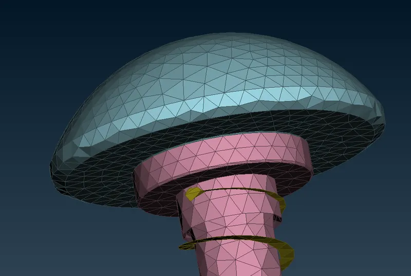
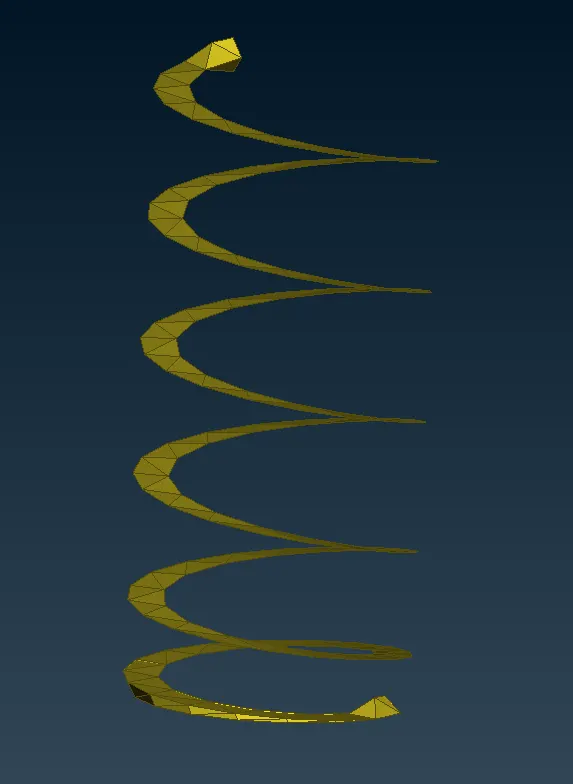
As we can clearly see in above two images that geometry is completely changed specially in case of spring.
why this issue surfaced?
This is because the mesh size we have choosen is greater than the cross-sectional are of spring and other steep curved suraces. so ANSA dosent properly distributes mesh over surface without distorting them, with help of measure tool the distance between cross section is near to 3 and mesh size is 5 to due to larger mesh size this problem is surfaced To cure this problem go with smaller mesh sizes.
Mesh size 3mm
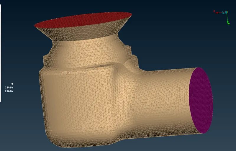
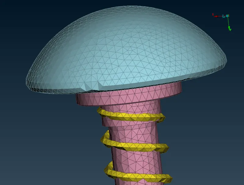
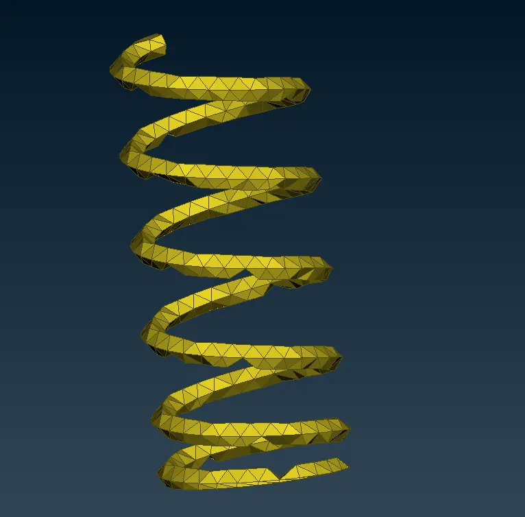
Geometry is better than when we used 5mm mesh but is still not in acceptable shape, so we will further proceed with more finer mesh.
Mesh size 1mm
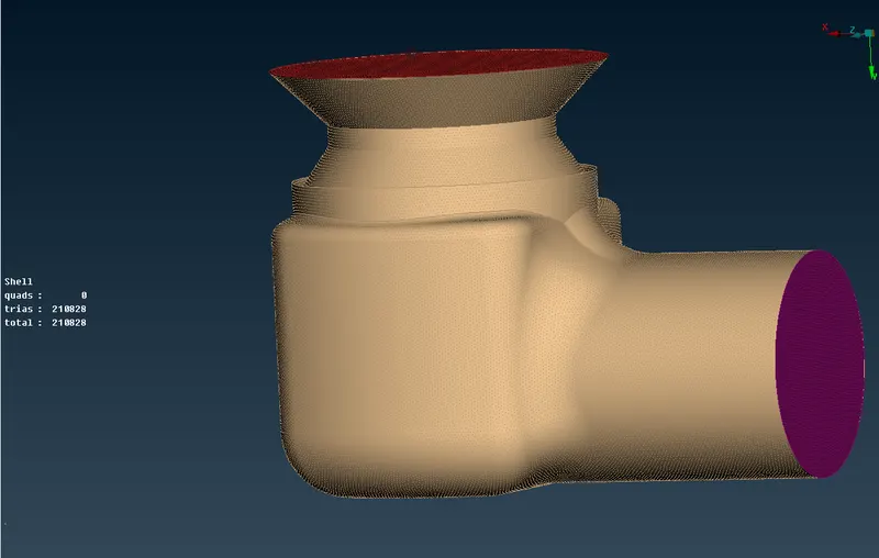
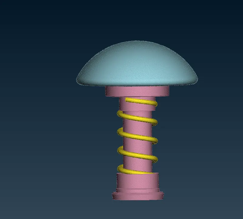
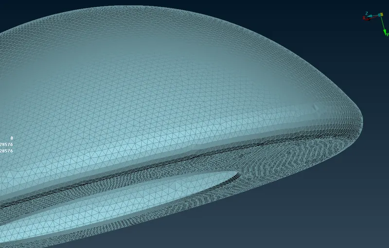
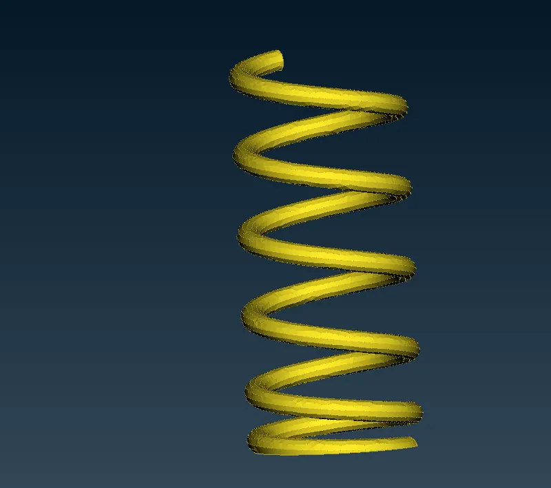
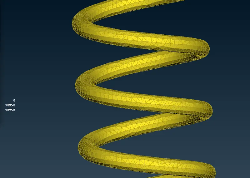
So with the use of 1mm mesh size we have now finally obtained a proper geometry , this is because 1mm is much less than any cross sectional length in whole geometry.
Link for Geometry
https://drive.google.com/file/d/1lL_UTU-A3IvOPqLm629H50qnq8XP-dzO/view?usp=sharing
Conclusion-
- Meshing on pressure valve, even seen different components inside valve.
- Use of PID region to assign different regions on geometry.
- Affect of different mesh sizes on construction and appearence of geometry, finer mesh gives better result than larger mesh
- mesh size is decided by experimental methods
- Learnt use of different boolean operations and entity and loop tools
- Used new tool to create new suraces
- learnt about single and double cons and why single cons need to be eliminated
- used wire frame mode and got familiar with its uses and importance while working on geometry.