Week 2 Challenge : Surface meshing on a Pressure valve
AIM :
To do the surface mesh for a given pressure valve by using mesh element type as 'Tria' for three different cases with three different mesh target lengths as 1, 3, and 5 mm respectively.
OBJECTIVES :
- To check for geometrical errors in the given model and to perform the respective topological clean up.
- To set PIDs ( Property identifier ) for different components of the model.
- To do the surface mesh for a given pressure valve by using mesh element type as 'Tria' for three different cases with three different mesh target lengths as 1, 3, and 5 mm respectively.
- To compare those three cases.
Tools used :
MENUBAR>Drawing Styles>Shadow - This flag turns on and off the shadow drawing style.
MENUBAR>Drawing Styles>Wire - This flag activates the wire model representation of the geometry and the FE-Model.
MENUBAR>Faces Draw>Cross Hatches - This flag activates and deactivates the visibility of Faces' cross-hatches. As this flag is activated, green isoparametric lines that lie on the visible Faces appear. If the Faces are linked Faces the color of the crosshatch is orange.
MENUBAR>Tools>Checks>Geometry - This function locates geometrical problems of the model such as Unmeshed Macros, Unchecked Faces, Needle Faces, Collapsed Cons, Triple Cons, Overlaps and Cracks.
MENUBAR>Faces Draw>Single - This flag activates and deactivates the visibility of single (red) CONS.
TOPO>Hot Points>Insert - This function creates or projects Hot Points by hovering positions on CONS or 3d curves or 1d FE elements.
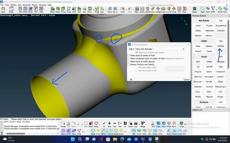
TOPO>CONS>Fill Hole - This function fills holes on Faces. The holes can be of any shape. Such internal openings can be selected individually, or automatically among the visible ones if they fall below a user specified diameter value. There is the option to create automatically 3D Curves, Points or Connection Points of the removed holes, in order to mark their shape and position for reference.
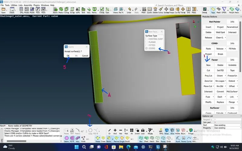
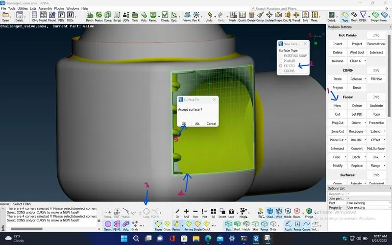
TOPO>Faces>New - This function defines a new surface by selecting its boundary curves and creates a corresponding face that covers the new surface. The calculated surface appears as a net.
New [COONS] -
This function defines a new multi-patch Face and Surface, using the COONS interpolation principal. This is an easy way to define a new surface by its boundary curves. After the mathematical definition is finished, the calculated surface appears as a net. A relative window gives the ability to accept or to reject the calculated surface. When only three boundary sides are selected, there is the ability to choose between two alternative definitions for the fourth generated side, one is to be straight and the other is to have a shape similar to its opposite side.
New [EXISTING SURF] -
This function defines a new Face laying on an existing surface.
New [PLANAR] -
This function defines a new planar face. The underlying surface is automatically created.
New [FITTED] -
The FITTED option is used for the definition of a non-planar Face. The created Face fits to the selected boundaries.
MENUBAR>Feature Selection>Line Options>Loop - Selects a closed loop of edges, perimeters or curves. Any internal or external perimeter is considered a loop.
MENUBAR>Feature Selection>ENT - Selects any kind of entity (the kind of entity depends on the ANSA function which is in use) one by one or multiple entities by box selection.
MENUBAR>Feature Selection>Surface Options>PID Region - If the 'PID Region' flag is activated, then by picking an element (shell or solid) of a particular PID, ANSA automatically selects all the connected visible elements, which are assigned with the particular PID.
TOPO>Faces>Orient - This function sets a uniform orientation direction to all visible Faces according to the orientation of the majority of the Faces. The mesh elements that will be generated, or those already existing, also obtain a uniform orientation.
MENUBAR>Lists>Properties - This function facilitates property management. A list of the properties existing in the file is available. Management windows, such as this one, provide filtering, sorting and selection capabilities on the listed entities as well as definition of new entities.
TOPO>Faces>Cut - This function cuts (splits) an existing Face or joins faces if inverse operation is applied (right mouse button).
It does not require the existence of Hot Points since it can be applied directly on an arbitrary position of a CONS.
MESH>Macros>Join - This function eliminates a Macro Area boundary segment between two adjacent Macro Areas. This way, two Macro Areas are joined to be treated as one, larger Macro Area.
MESH>Perimeters>Length - This function defines the element length on selected perimeter segments or macro areas. The element length may be explicitly declared or may be declared as a factor to be multiplied by the existing element length.
MENUBAR>Utilities>Mesh Parameters - This function opens the 'Mesh Parameters' window, where the user can define the parameters for the Reconstruction, Reshape and Fix functions.
MENUBAR>Utilities>Quality criteria - Select and set the respective quality criteria for the corresponding elements to perform the Quality Checks (Hidden Mode). Also set the general presentation settings concerning the ANSA workspace.
MESH>Mesh Generation>Spot Mesh - This function automatically meshes Macro and FE shell mesh areas using a special meshing method for Macro-Areas that have 'weld spot' nodes on their surface. The Spot Mesh algorithm gives better results than the free meshing method and creates the optimum number of shell elements, taking into account the element type already selected and the defined meshing parameters.
The function may be applied to selected unmeshed Macros, or to all visible Macros according to the chosen option (Selected or Visible respectively). The Re-Generate option applied to selected Macro Areas where, firstly, erases existing mesh, if any, and secondly meshes them using the Spot Mesh algorithm. The resulting shell elements are of first or second order shell elements according to the status of the 2nd Ord flag.
MESH>Mesh Generation>Erase - This function deletes the mesh of selected or of all visible Macro-Areas, according to the option selected.
MENUBAR>Utilities>Measure - This function performs various measurements according to the corresponding Selection Mode. The applied measurements can be saved and viewed at a later stage.
MENUBAR>Utilities>Snapshot - Take snapshots from the drawing area or from any ANSA window. Depending on the selected option the image can be: POSTSCRIPT, RGB, TIFF, JPEG, PNG or BMP.
PROCEDURE :
Step 1: Upload the given valve model into ANSA by using MENUBAR>File>Open
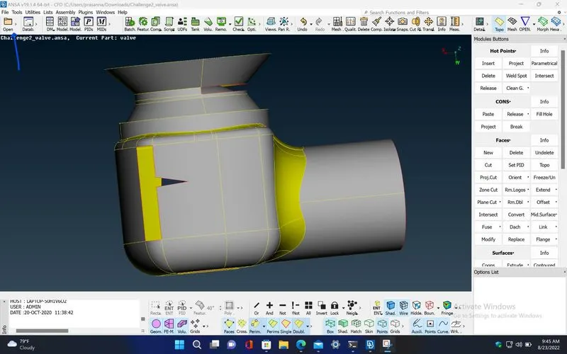
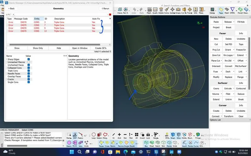
Step 2: Check for any geometrical errors (Mainly the single cons) by executing the check manager in MENUBAR>Tools>Checks>Geometry
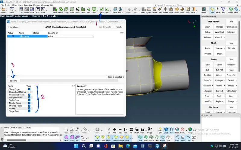
Step 3: The check manager will show all geometrical errors in the model that are selected in the list before executing.
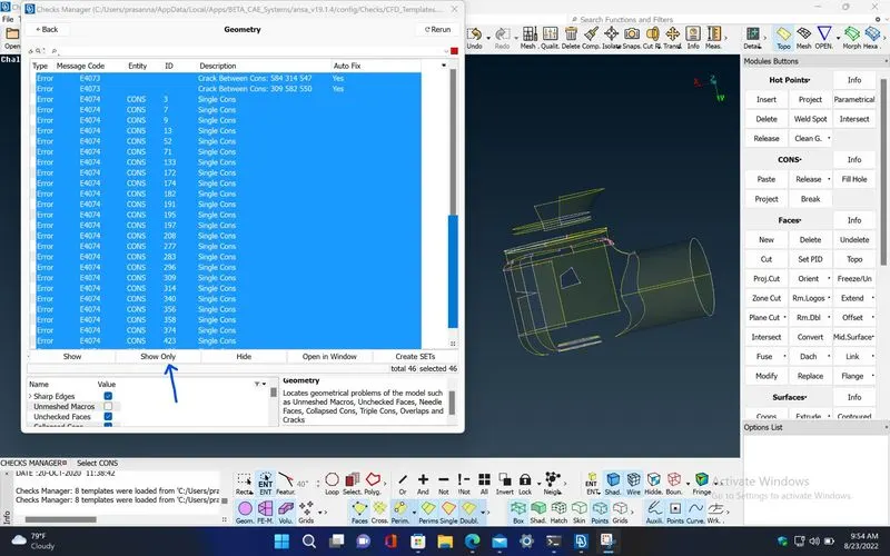
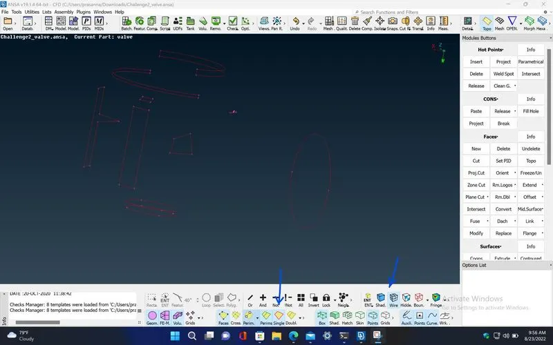
Step 4: By using wire drawing style and also selecting only the single con face draw option, every single con present in the model can be viewed.
Step 5: Use fill hole option in TOPO>CONS>Fill Hole, to fill some of the cracks and holes present in the model.
Step 6: Create new faces where single cons exist by using TOPO>Faces> New and choose the suitable face for that geometry.
TOPO>Faces> New[COONS]
TOPO>Faces> New[FITTED]
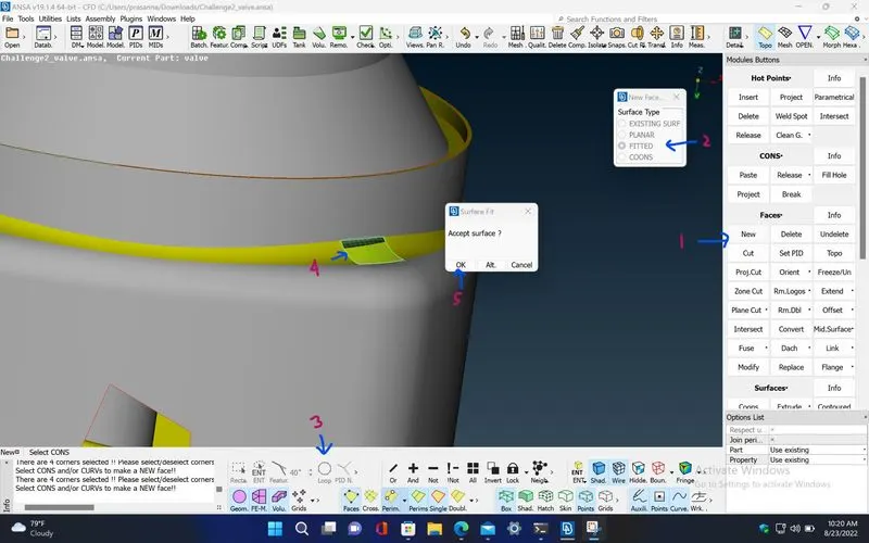
Step 7: After doing all the topological clean ups , verify once again by using check manager if any errors present.
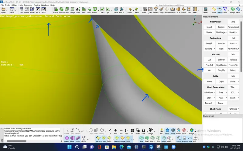
Step 8: Since some faces of the geometry have very smaller lengths and sharp edges, this will affect the geometry while meshing. So, we join two surfaces of smaller lengths using MESH>Macros>Join
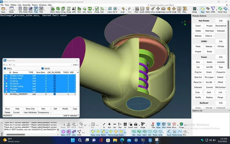
Step 9 : Assign PIDs for every individual components of the model using MENUBAR>Lists>Properties
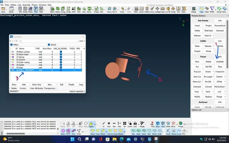
Step 10: Delete the leftover PID.
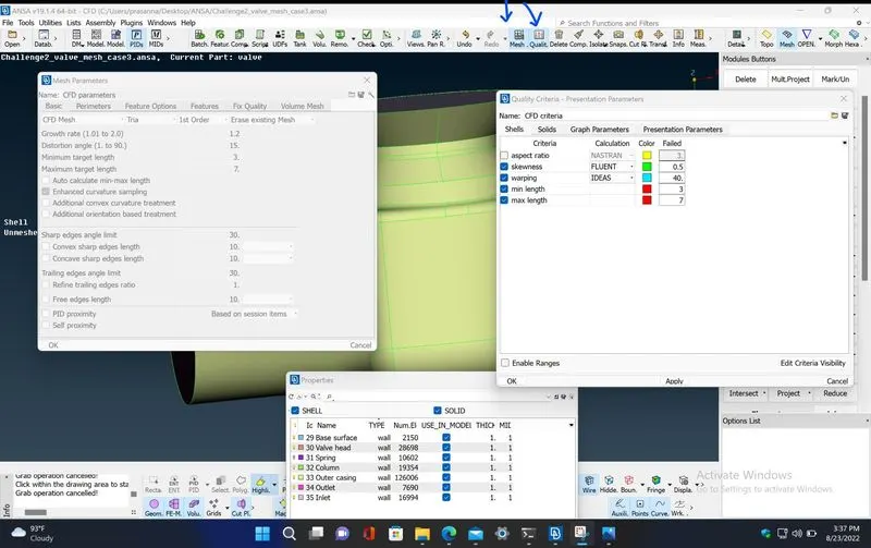
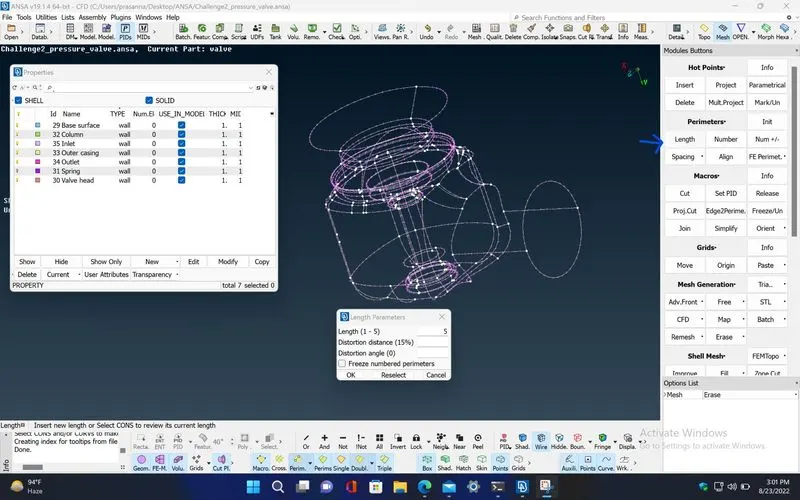
Step 11: For case 1, Provide the mesh length as 5mm in both perimeters and macros under MESH>Perimeters>Length, also provide maximum and minimum target length as 3 and 7 mm respectively in 'mesh parameter' and also in 'quality criteria'.
Step 12 : Generate the surface mesh using spot mesh algorithm under MESH>Mesh Generation>Spot Mesh
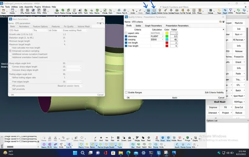
Step 13: Before getting into case 2, Erase the existing mesh using MESH>Mesh Generation>Erase. For case 2, Provide the mesh length as 3mm in both perimeters and macros under MESH>Perimeters>Length, also provide maximum and minimum target length as 2 and 4 mm respectively in 'mesh parameter' and also in 'quality criteria'. Now, do the surface mesh as before.
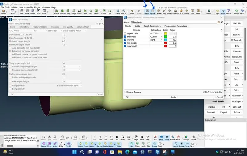
Step 14: Before getting into case 3, Erase the existing mesh using MESH>Mesh Generation>Erase. For case 3, Provide the mesh length as 1mm in both perimeters and macros under MESH>Perimeters>Length, also provide maximum and minimum target length as 0.5 and 1 mm respectively in 'mesh parameter' and also in 'quality criteria'. Now, do the surface mesh as before.
RESULTS :
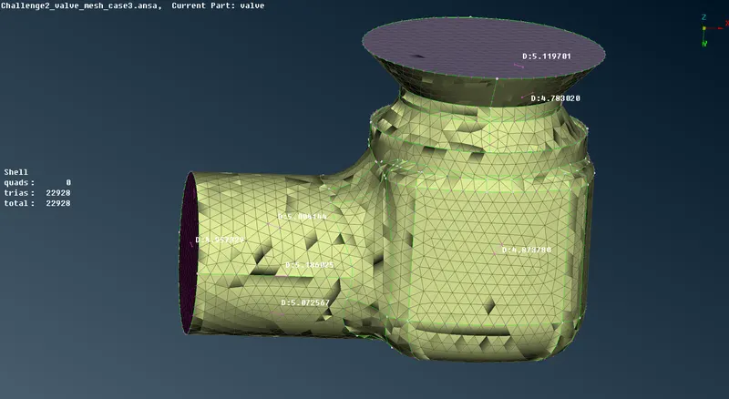
Case 1 : Mesh target length is 5mm.
https://drive.google.com/file/d/1RuEt1C7fcfl7rAkJA8Z1OmAX52dX7UNu/view?usp=sharing
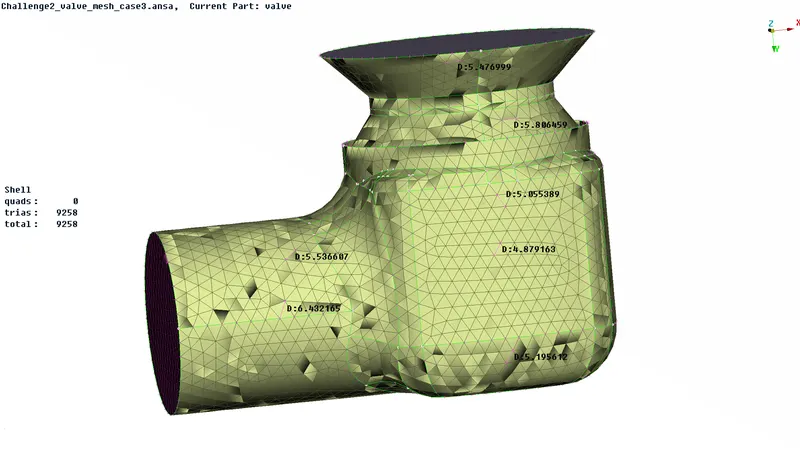
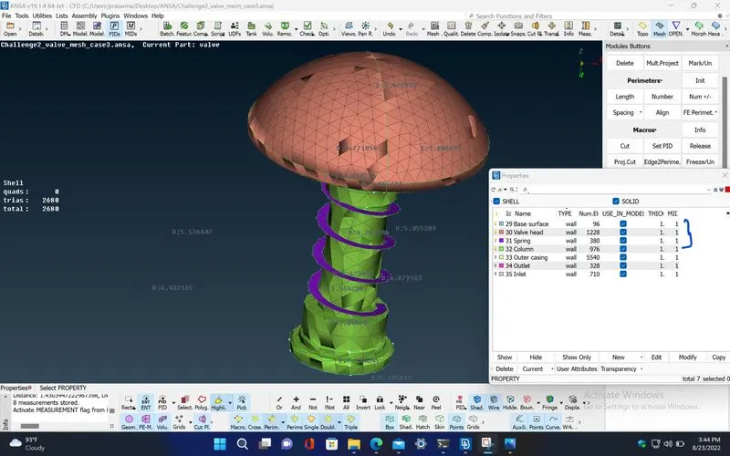
Case 2 : Mesh target length is 3mm.
https://drive.google.com/file/d/1Az1dUwjdXs4qSo2YcjnPBYmCGTV4GWkI/view?usp=sharing
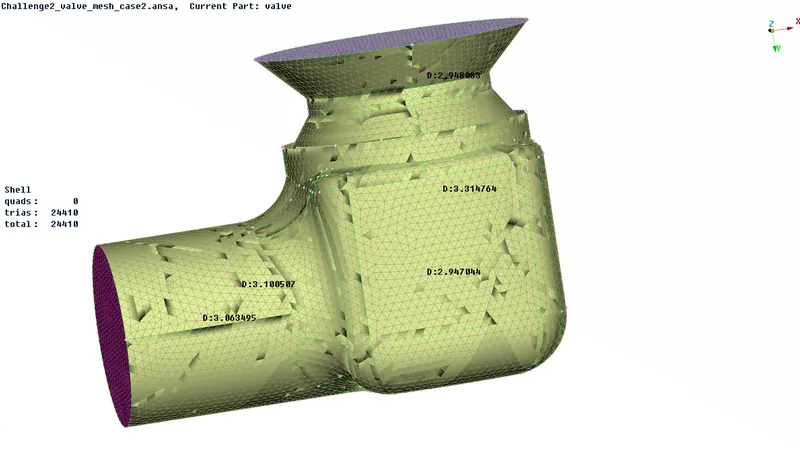
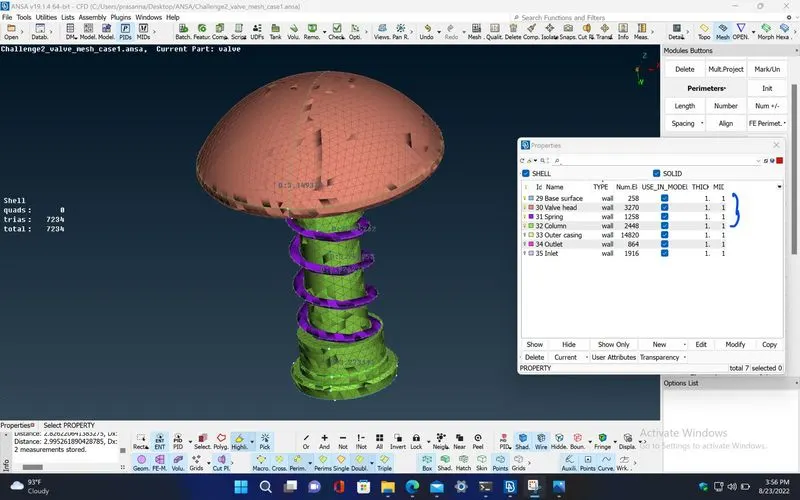
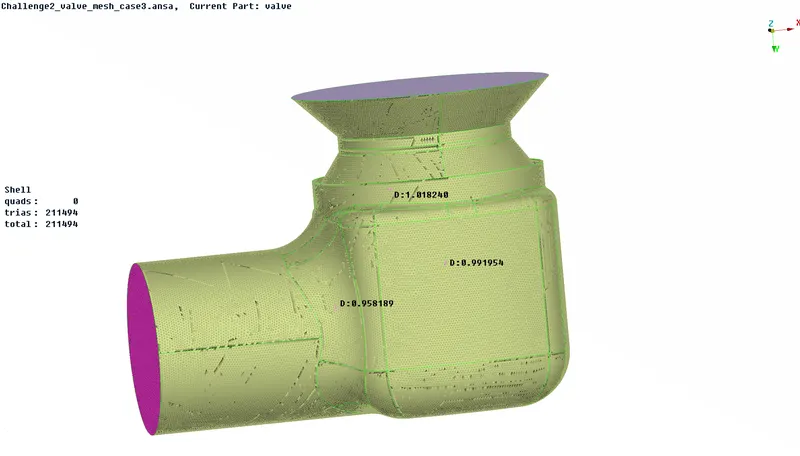
Case 3 : Mesh target length is 1mm.
https://drive.google.com/file/d/1yZ4SFVbXKwLxVTuV92-eCxwn0Yvm8HH7/view?usp=sharing
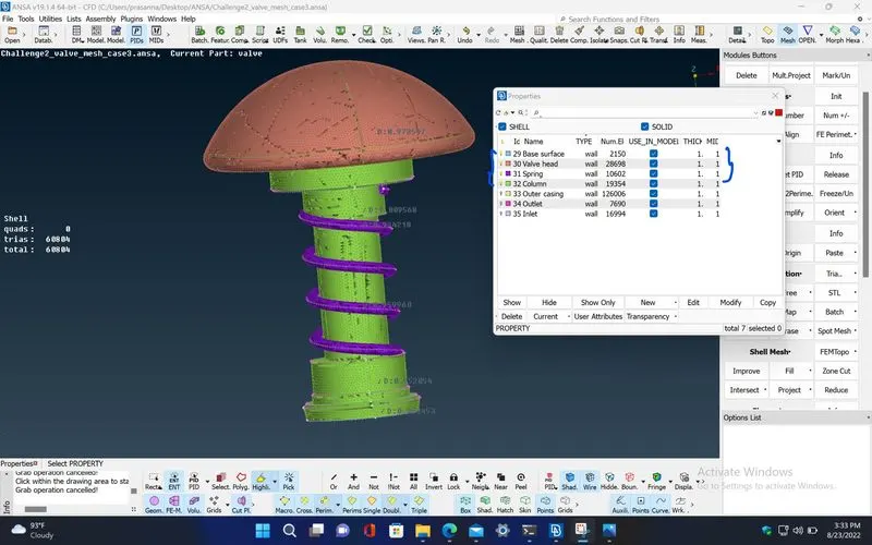
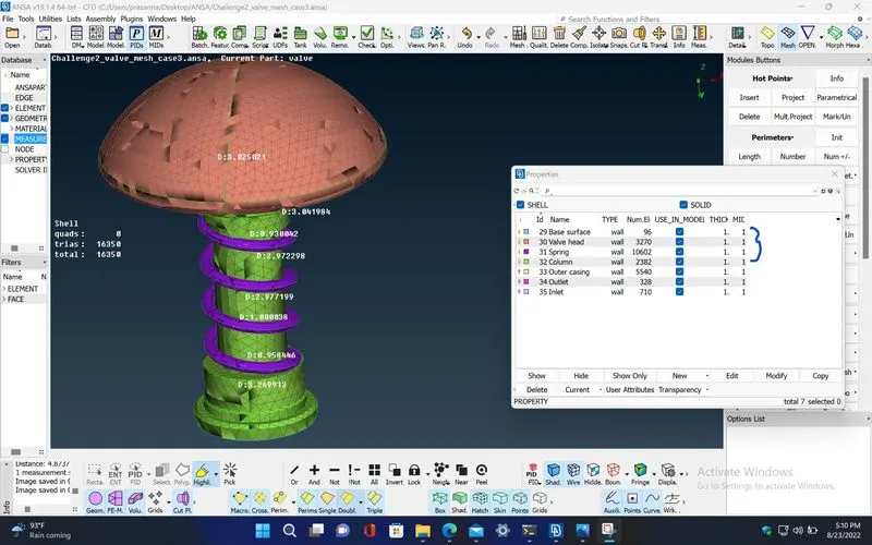
Final : Different meshing lengths for different PIDs to get a optimum result.
- for inlet, outlet, outer casing and base surface PIDs, Mesh length given is 5mm.
- for valve head and column PIDs, the given mesh length is 3mm.
- for spring, the mesh length is 1mm.
https://drive.google.com/file/d/1gnHN_vObMXOVmLJVHGjZ63PZ1xr6EML0/view?usp=sharing
CONCLUSION :
Hence, from the above result, we can observe that,
- in case 1, since the mesh length is 5mm, the model geometry is not much accurate mainly the entire geometry of the spring has changed and it is due to the diameter of the spring which is less than the mesh length.
- in case 2, the mesh length is 3mm, so, the geometry is fine compared to the previous case but still, in the spring , the mesh is coarse though its geometry is retained.
- in case 3, the length of the mesh is 1mm , here, the mesh is very fine even to capture some of the geometry along the curves. Although the mesh is so accurate, it will take more computational time for generating it compared to the previous cases
So, In order to generate a better optimum mesh which takes less computational time, we can assign different mesh lengths for different components to get a optimum result.