Pre-Processing of Safety Pressure Valve using ANSA.
AIM:
To study surface meshing on given geometry, Make three different models with 3 different target lengths.
For the given model, check for the geometrical errors and perform Topology cleanup accordingly. Set three different target lengths as three different cases and mesh the model.
- Target length = 1mm, 3 mm and 5 mm (i.e. 3 cases)
- Element type = Tria
INTRODUCTION:
Pressure Relief Valves
A pressure Relief Valve is a safety device designed to protect a pressurized vessel or system during an overpressure event.
An overpressure event refers to any condition which would cause pressure in a vessel or system to increase beyond the specified design pressure or maximum allowable working pressure (MAWP).
The primary purpose of a pressure Relief Valve is the protection of life and property by venting fluid from an overpressurized vessel.
Many electronic, pneumatic, and hydraulic systems exist today to control fluid system variables, such as pressure, temperature, and flow. Each of these systems requires a power source of some type, such as electricity or compressed air in order to operate. A pressure Relief Valve must be capable of operating at all times, especially during a period of power failure when system controls are nonfunctional. The sole source of power for the pressure Relief Valve, therefore, is the process fluid.
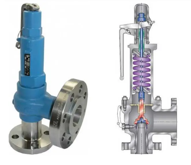
Since reliability is directly related to the complexity of the device, it is important that the design of the pressure Relief Valve be as simple as possible.
In this Project, the Gate Valve geometry is pre-processed for CFD simulation, to obtain quality surface and Volume mesh.
PROCEDURE:
Geometry:
The model provided has geometrical errors which are to be corrected prior to meshing.
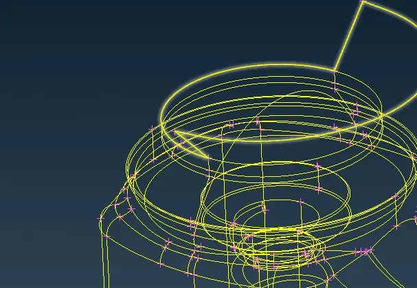
As ANSA is launched and geometry is imported, it first appears in wireframe mode.
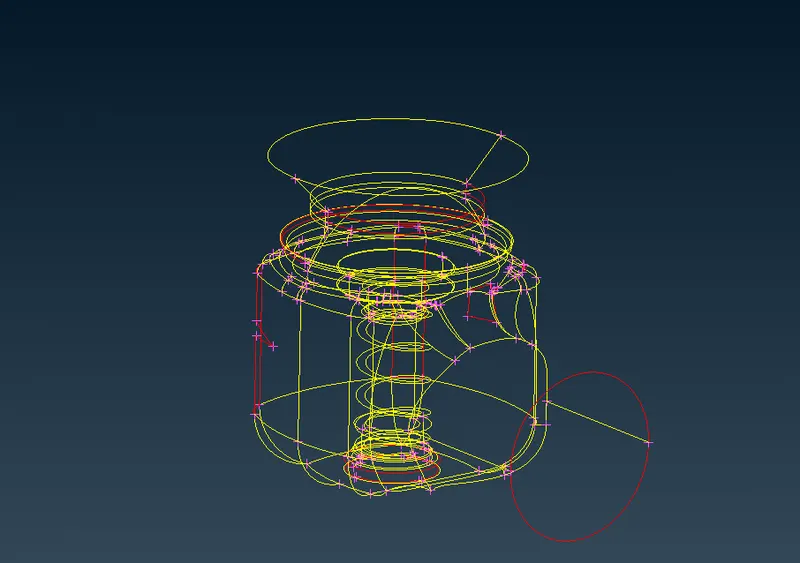
Enable the shadow mode  for visualizing surfaces.
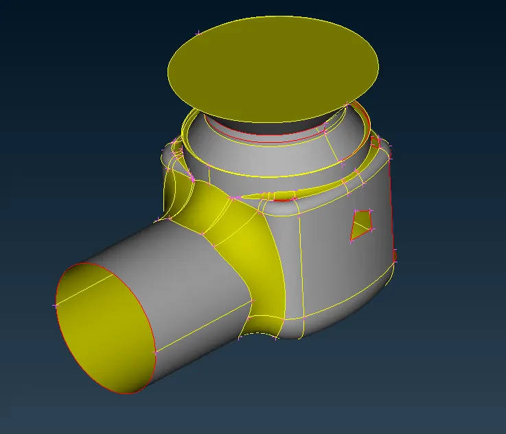
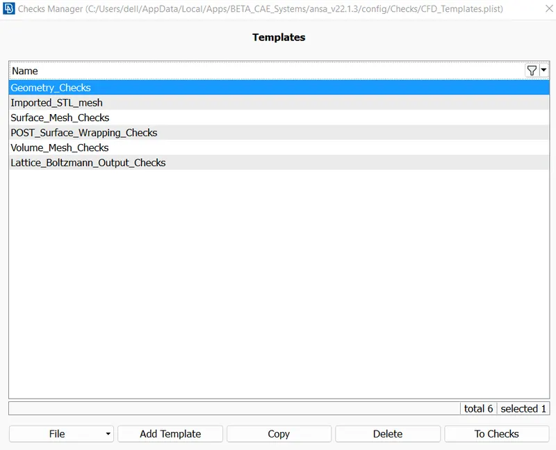
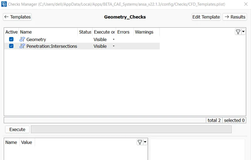
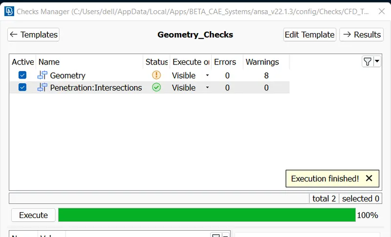
By visual inspection, red CONS can be easily identified. After importing the geometry click on checks manager small arrow---> geometry checks ---> To checks ---> Execute.
----------------------------------------------------------------------------------------------------------------------------
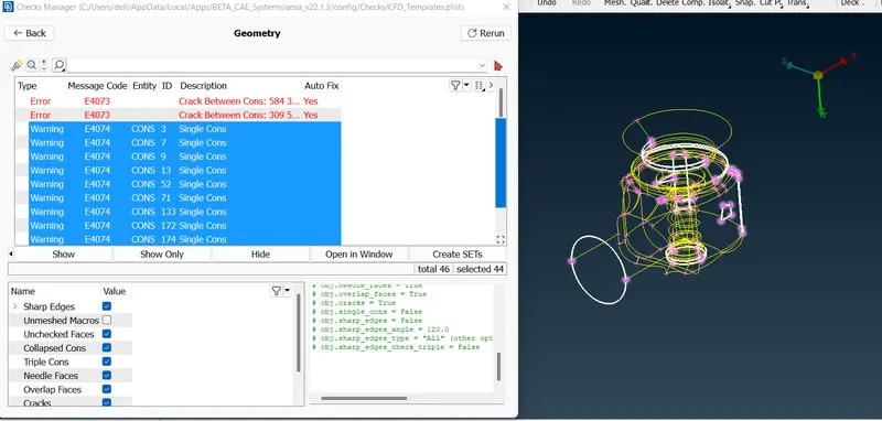
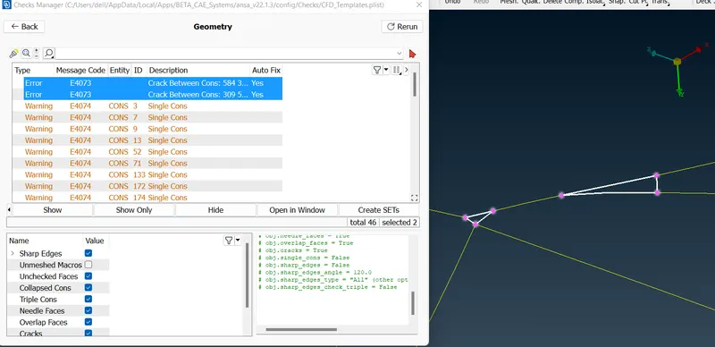
Several errors were identified. By using visible options,

----------------------------------------------------------------------------------------------------------------------------
Double click on geometry, single CONS, cracks are identified.
Intersections:
----------------------------------------------------------------------------------------------------------------------------
SINGLE CONS
This all shows the open spaces in the geometry, to overcome them we have to fill them before meshing
To fill the holes, we can use  New command from face dropdown, in which we can new faces on the holes in the geometry.
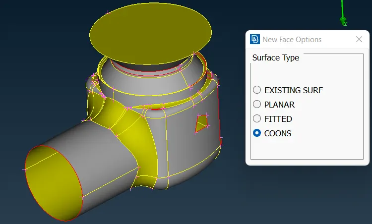
We can repair faces by 4 surface types option:
1) Existing Surface: It is used to fix features where already a surface is present.
2) Planar: Used to generate a flat, 2D surface.
3) Fitted: Generates and attempt to fit a surface between bounding yellow CONS. If surface is not suitable then Alt. is used to get the optimum fitted surface.
4) Coons: Coons are used to create curvature surfaces between specified boundaries.
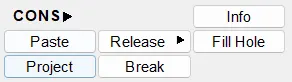
Alternatively, the fill hole option under cons can be used to fill the simpler curves.
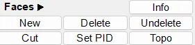
Start clean-up by using Topo option, to automatically eliminate some irregularities and geometry errors.
-----------------------------------------------------------------------------------------------------------------------------
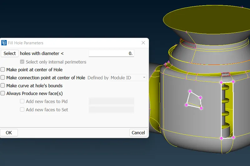
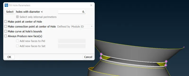
Use either fillhole/Coons option to eliminate the given geometry errors, we can select the edges ny using loops in COONS option. Displayed is the usage of fillhole option for cleam-up of red Cones.
fillhole--->Fill Hole Parameters--> Select the edge, it will automatically select the enclosed edges--> OK.
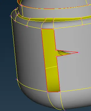
Repaired Faces:
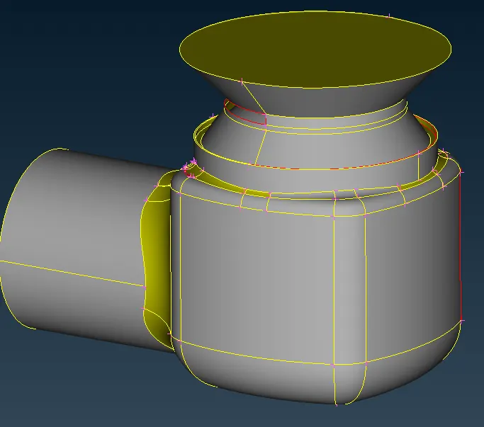
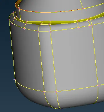
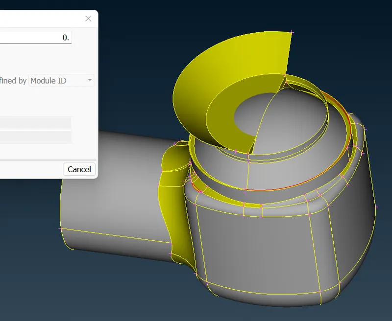
We cannot use fillhole option in this surface because this option can form connections with surfaces therefore it will gives the intersecting surface with the column head (as shown below); therefore we need to use Faces-->New-->Coons option for this Red CONS.
Intersection with column head:
----------------------------------------------------------------------------------------------------------------------------
COONS
BEFORE AFTER
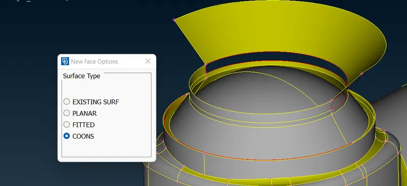
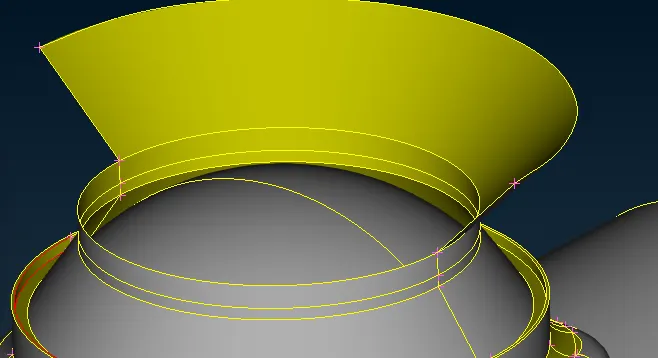
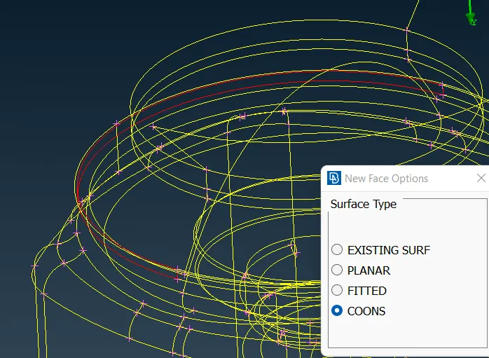
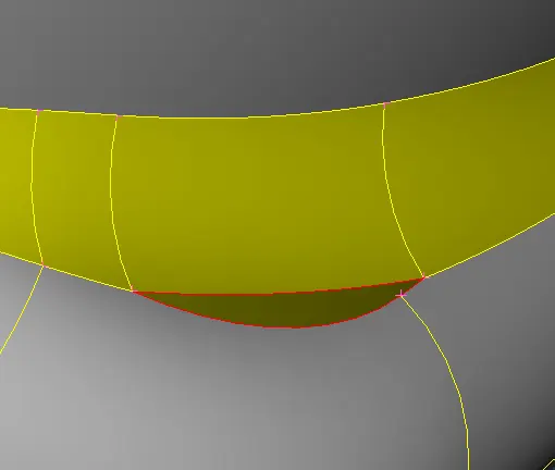
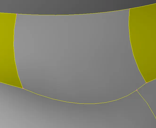
Note: The above `uarr` surface is created by first deleting the adjoining face of hole and then repairing it by COONS.
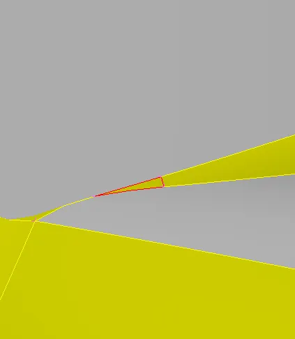
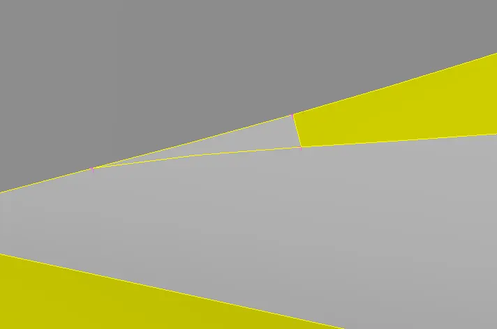
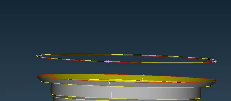
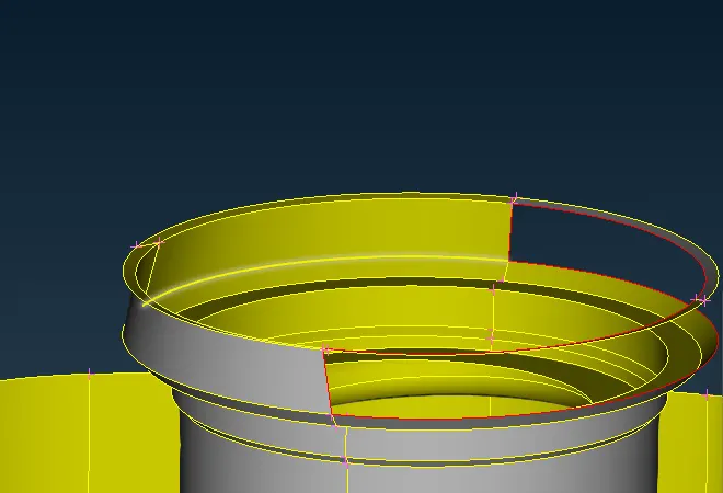
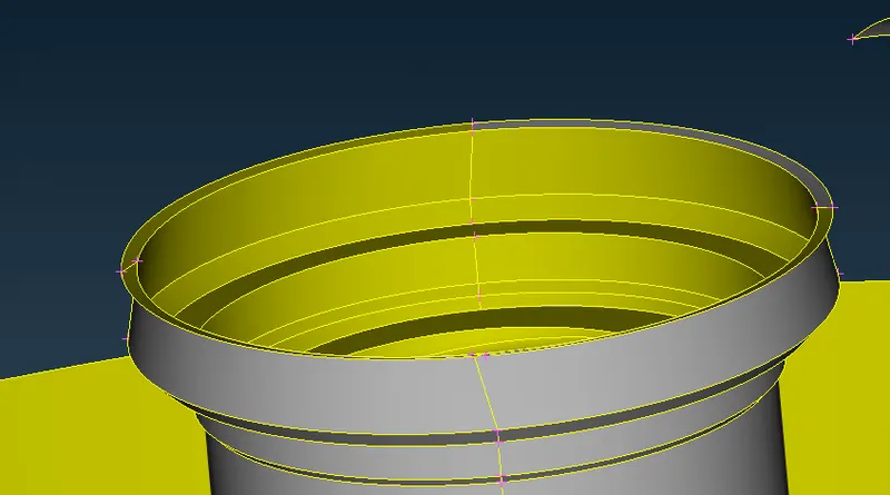
Note: This two step procedure was adopted for clean-up because if done without changing the loop option  to entity mode before selecting the CONS, then geometry will give a distorted surface between these two planes as shown below. After the first step loop option could be enabled.
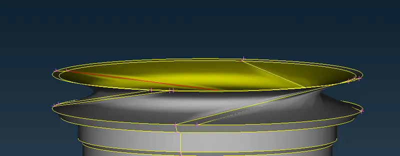
---------------------------------------------------------------------------------------------------------------------------
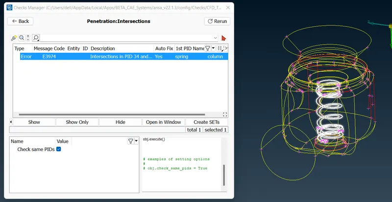
Intersection Errors
For fixing the intersection errors between spring and column; hide the outer body of gate valve by using NOT option  along with PID Region
  and lock
  the geometry to conserve the current state.
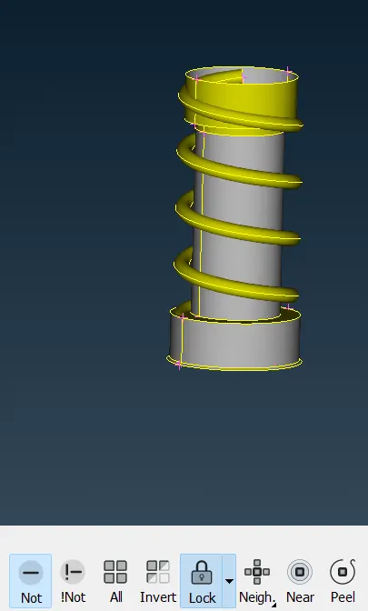
Assign the  PIDs to Spring and Column. (PID: Part Identity)
Hide the spring by option and create a new PID name column. Right click on PID name column---> Apply -->
Select the column ---> middle click button.
Similary use  and then use
  to hide Column.
Change the  entity mode to PID mode
  to see the assigned PID with color.
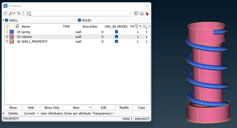
Under the Faces use Intersect option to clear the intersections.
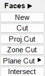
Select the first and second objects in any order.
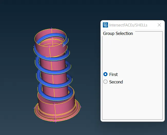
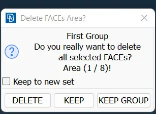
Then the dialog box appears which provides option for which surface to Keep/Delete.
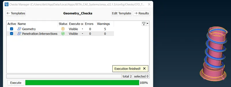
Then Again go to Checks manager to check for any errors and warnings after cleaning intersections.
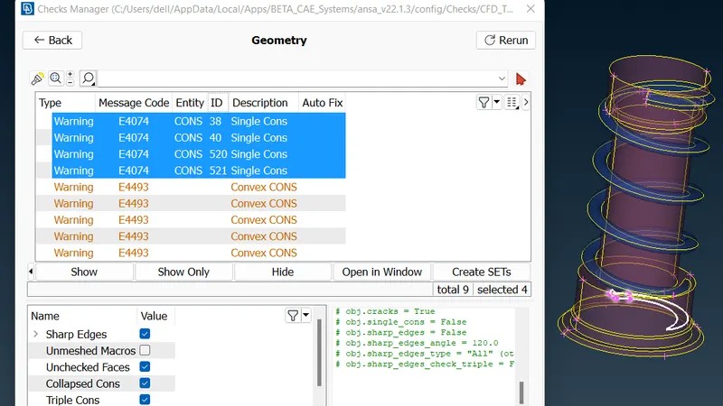
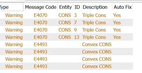
The Checks Manager don't show any errors except few convex CONS, Single CONS warnings. The extra remaining surfaces can be deleted.
----------------------------------------------------------------------------------------------------------------------------
Cover the Inlet and Outlet of Pressure Valve by using COONS/Planar/Fill Hole option before meshing as fluid domain will be present inside these boundaries.
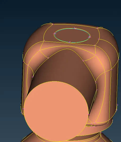
Neglect the Triple CONS as these boundaries are necessary and cannot be avoided.
Do a final .
-----------------------------------------------------------------------------------------------------------------------------
MESHING
To mesh the given geometry we will provide the target length as 1mm, 3mm & 5mm one by one in each of the following cases below.

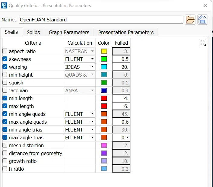
Providing the Target length, Assigning Minimum Target Length & Maximum Target Length in the Mesh Parameter for the each case and also providing the Element type as ‘Tria’.
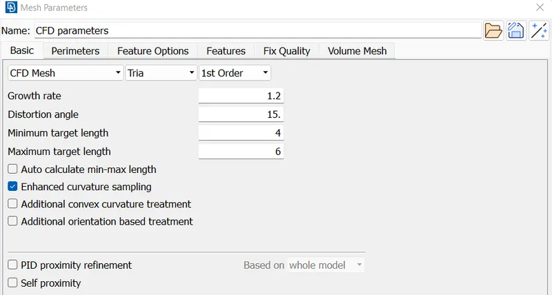
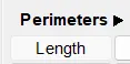
Use perimeters-->length option to give the target length.
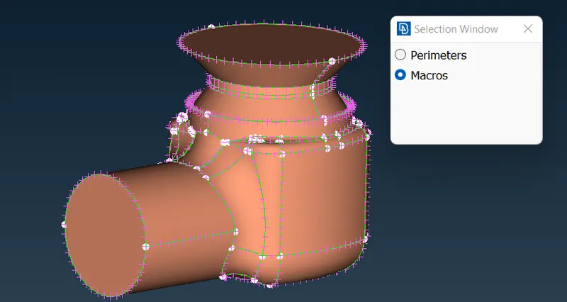
Specify Perimeters and Macros for given target length.
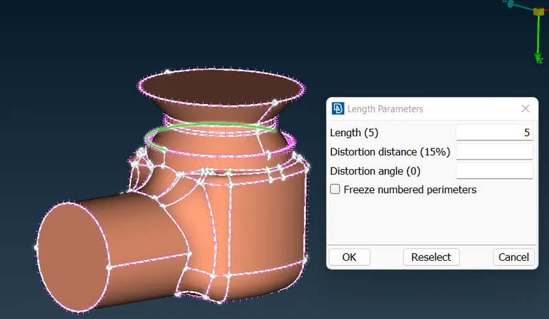
First we will assign the Length to Perimeters and then the Macros as 1mm by selecting the whole body.
After assigning the target length, select,
Mesh Generation →">→→ CFD
CFD mesh is applied.
-----------------------------------------------------------------------------------------------------------------------------
RESULTS
CASE 1:- Target element length = 5mm
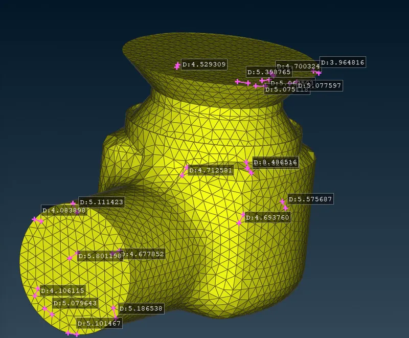
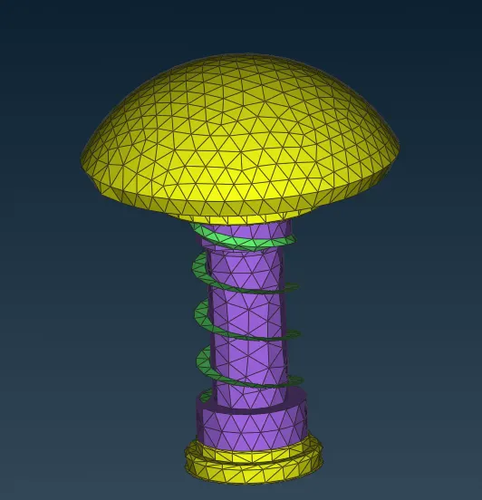
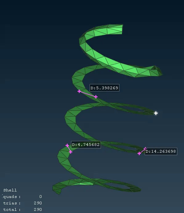
From the figure this can be identified that the target length of 5mm was not suitable for spring as the minimum geometrical dimension was less than 5mm. Since the element length assigned would be greater than that of the spring dimensions, therefore the mesh is unable to capture the curvature of the spring.In the above case it can be seen that mesh was able to capture the geometry of Body and Valve Head.
CASE 2:- Target element length = 3mm
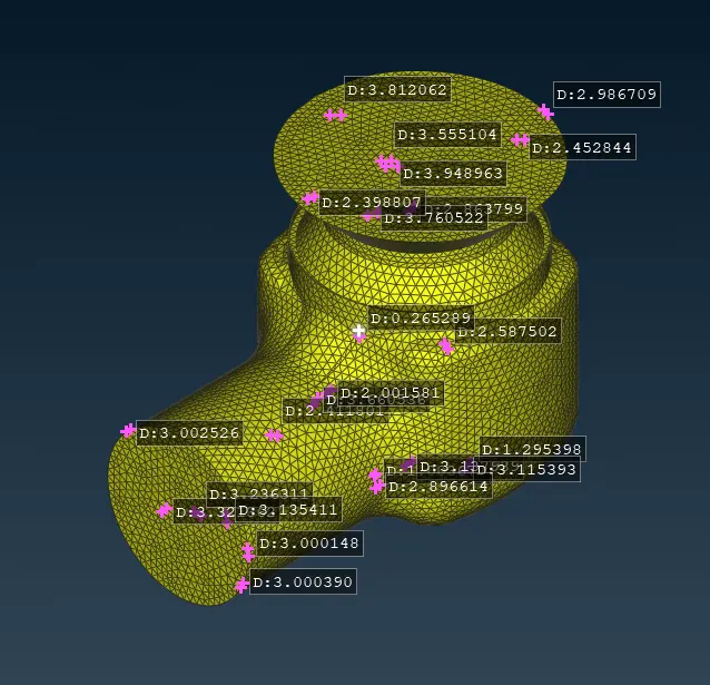
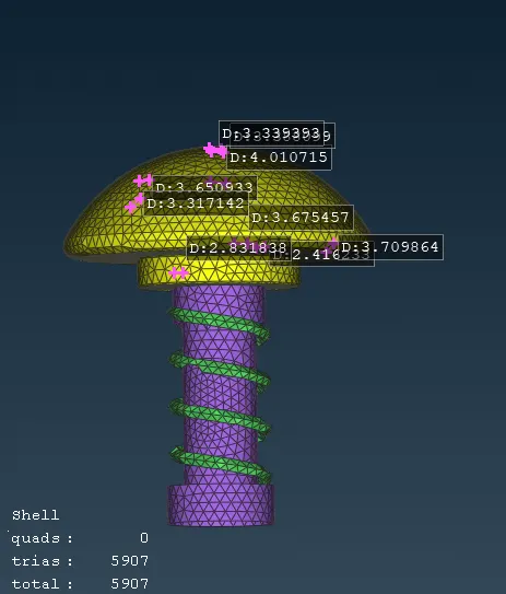
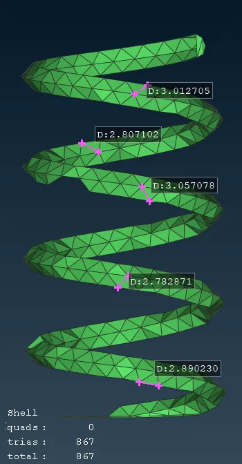
For target length of 3mm the mesh is able to capture the curvature of the spring but still spring appears distorted. In the above case it can be seen that there is good meshing of Body and Valve Head.
CASE 3:- Target element length = 1mm
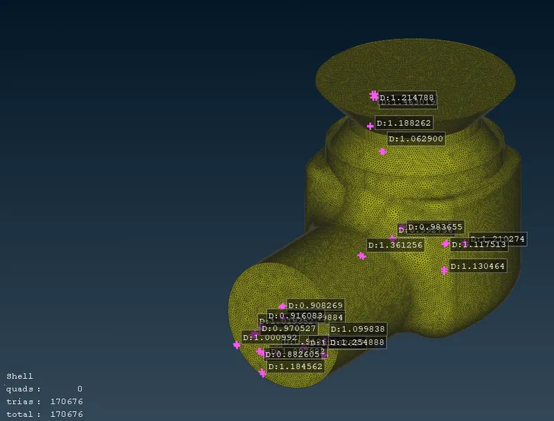
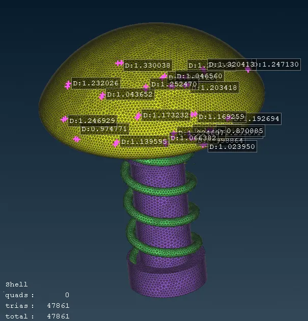
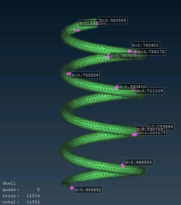
Here we can see that the mesh has almost fully captured the geometry of the whole body. The curvature of the valve head has also been captured.
The mesh tried to capture most of the curvature of the spring. To efficiently mesh the spring a mesh size smaller than 1mm would be needed.
CONCLUSION:-
It can be concluded that as the target mesh length increases the quality of the mesh becomes worse. Therefore it is recommended to use different mesh length for different parts of the geometry.
- In this case to mesh the Body, a mesh length of 5mm would also do the work.
- To mesh the Valve Head & Column, mesh length of 3-5mm would be okay. But the 3mm mesh size captures the curvature more efficiently.
- To mesh the spring it is highly recommended to use a mesh length of 1mm, since the other mesh size is unable to capture its surface and curvature.
LEARNING OUTCOMES:
- Methods of Error rectification for missing CONS, Holes in Geometries, repairing for intersections in geometry.
- Mesh target length assignment can be learned.
- Geometry visiblility status tools were used.
ANSA files link: https://drive.google.com/file/d/14Mg2H_eyf-4PiydHWBc6PZeMY-IbvP58/view?usp=sharing