Week 2 Challenge : Surface meshing on a Pressure valve
Surface meshing on a Pressure valve
Objectives:
For the given model, check for the geometrical errors and perform Topology cleanup accordingly. Set three different target lengths as three different cases and mesh the model.
- Target length = 1mm, 3 mm and 5 mm (i.e. 3 cases)
- Element type = Tria
Procedure:
Step 1) Import the geometry :
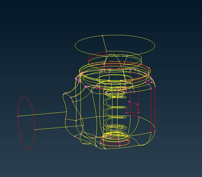
The imported geometry is in wire frame mode which is shown in figure below:
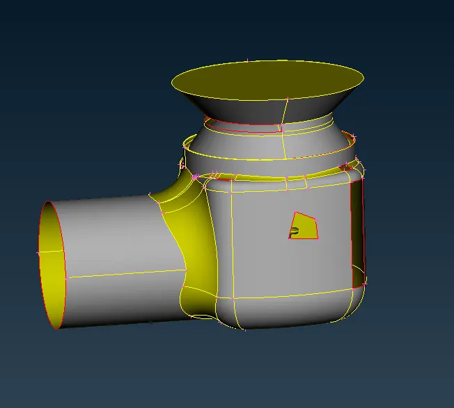
We enable the shadow mode to see the geometry :
Step 2) Remove Geometrical error:
Topo mode is used to check topology of model,our first task is to remove the errors present in geometry.
In order to do that we go to Check > Checks manager > Geometry checks > Execute
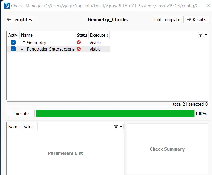
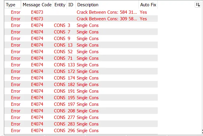
The above picture shows the errors which are present in the geometry you have to remove this errors. we first remove the single cons in order to do this we have to create a surface .Single cons is a missing surface their is no surface present in that region.Step to create surface is Topo > Faces > New after that the new pop up window shows this shows the desired surface type.
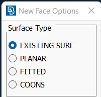
In this project we use 3 out of 4
Existing surf is used to fill holes which are present in existing surface.
We use existing surf,fitted and coons option to create surface on single cons.
We can also use fill hole option ie Topo > CONS > Fill Hole to fill the holes which are present on geometry. In this case triple cone is formed at bottom surface this is required surface so in this case we cannot consider triple cone is error.
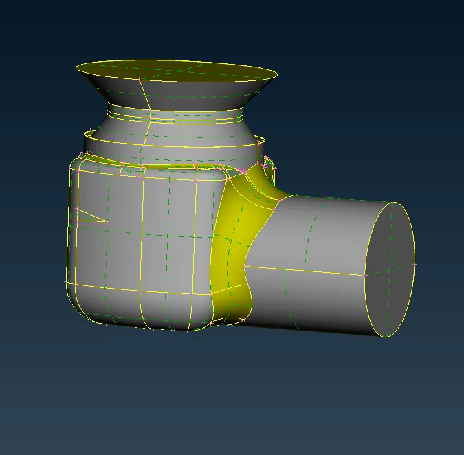
After removing all the error the geometry is shown in figure below:
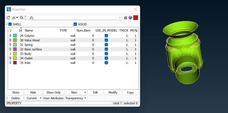
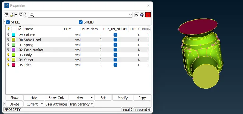
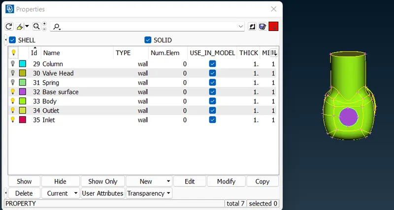
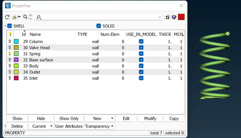
Step 2) Assigning the PIDs :
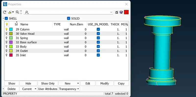
To assign the PID by using PID option which is shown as :
Body:
Inlet and outlet:
Base surface:
Spring:
Valve Head:
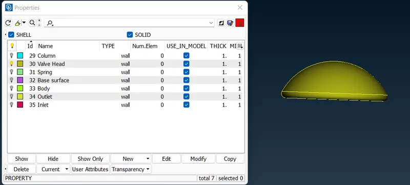
Column:
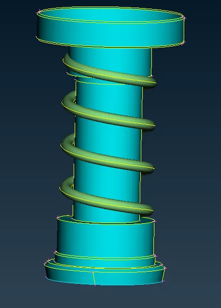
The second error is intersection and penetration error which is present in between the column and spring part.We have to remove this error : In order to do this we select the column and spring and lock this geometry for until we remove the intersection error.

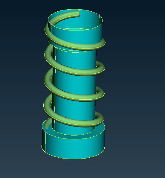
By using Not tool we Hide the unnecessary surface to view the actual intersection surface.

After using Not tool the geometry is look like:
We use intersect tool ie Topo > Faces > intersect then the new pop up is coming ie
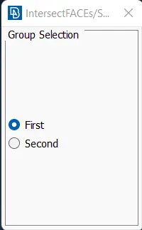
we select spring for first selection and in second selection we select column after that geometry is look like:
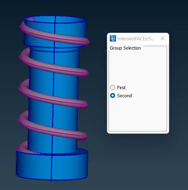
After that the new pop up comes then we keep the required surface and delete unnecessary surface then again check the error we can see error is removed.
Step 3) Meshing :
Case 1) Target length= 5 mm , Element type: Tria
- To mesh the geometry we use Mesh > perimeter > Length, In this we use both perimeter and macros and give length =5 mm
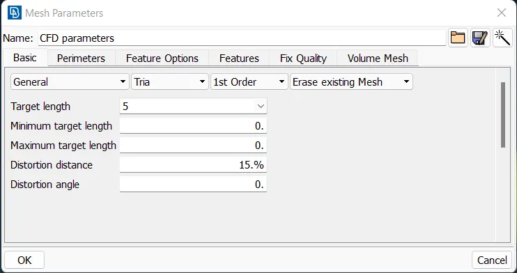
- In mesh parameter set target length =5 mm and select element type= Tria( Triangular)
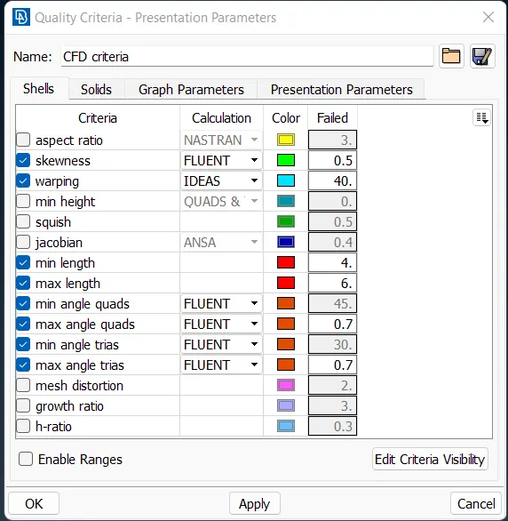
- In quality criteria we give maximum length =6 mm and minimum length=4 mm
- We can use PID region option and select component one by one to mesh the geometry.The internal component can be selected by using Not option or by using PID manager .
- In mesh generation we use spotmesh .
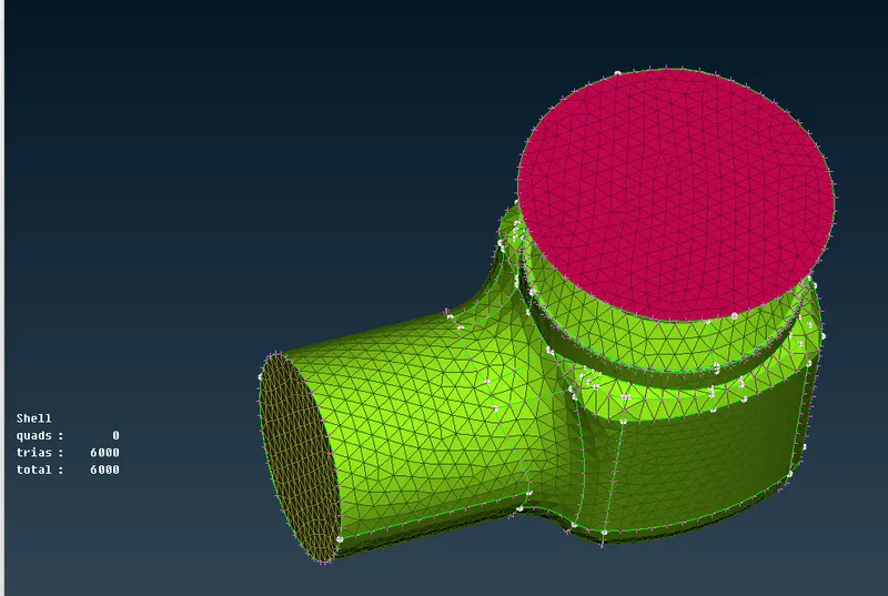
Inlet ,Outlet and body :
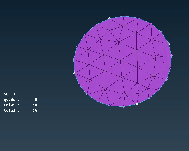
Base surface:
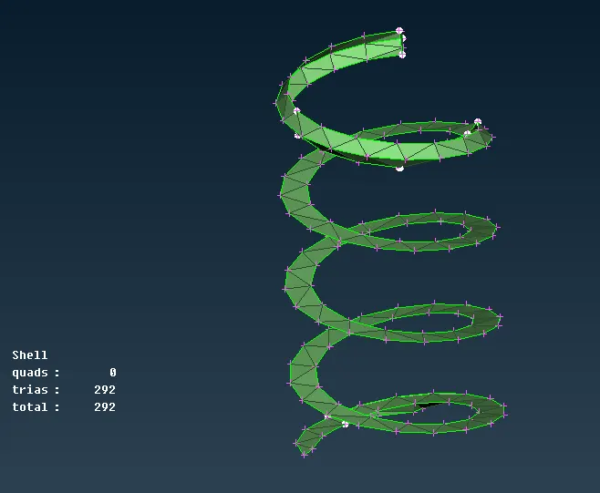
Spring :
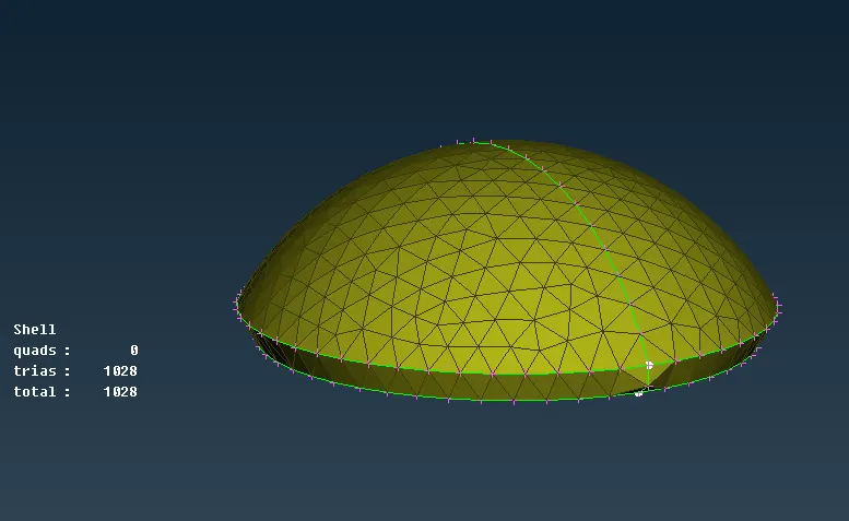
Valve Head :
Column:
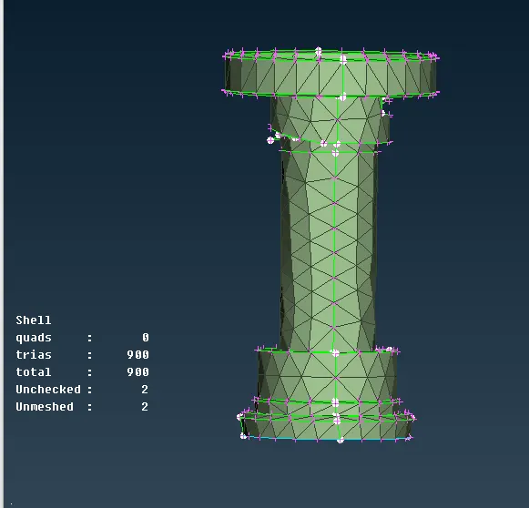
In this case the total cell count obtained is 8284 nos .we can see that the in 5 mm mesh size the outer body is captured well but minimum defeature is there.In spring the minimum target length is higher than the spring outer diameter so the spring is deformed for that mesh size.The column and valve head also defeatured due to the target length.
Case 2) Target length =3 mm
- To mesh the geometry we use Mesh > perimeter > Length, In this we use both perimeter and macros and give length =3 mm
- In mesh parameter set target length =3 mm and select element type= Tria( Triangular)
- In quality criteria we give maximum length =4mm and minimum length=2.5 mm
Inlet ,Outlet and body :
Base surface:
Spring :
Valve Head :
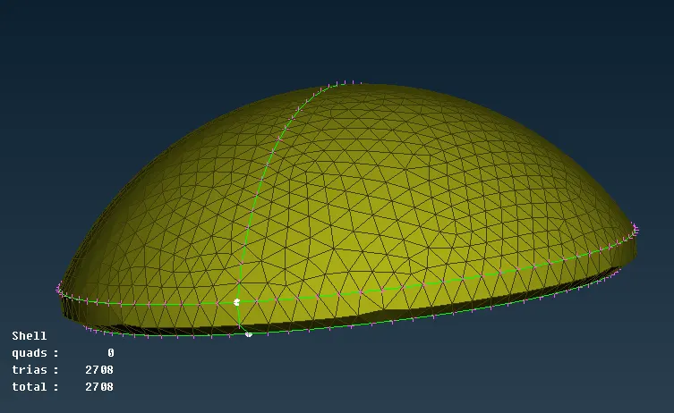
Column:
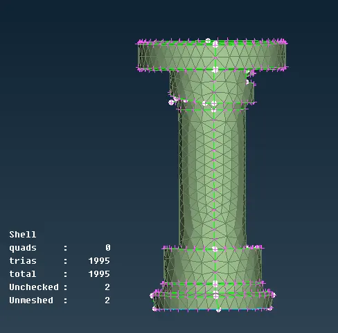
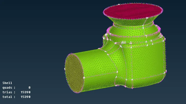
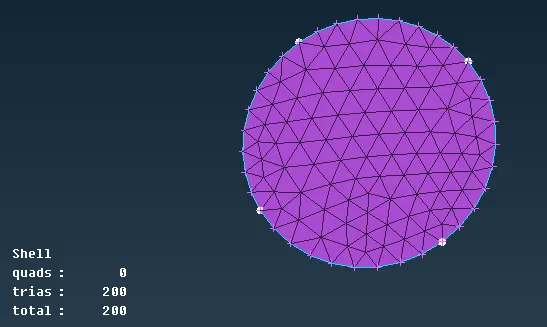
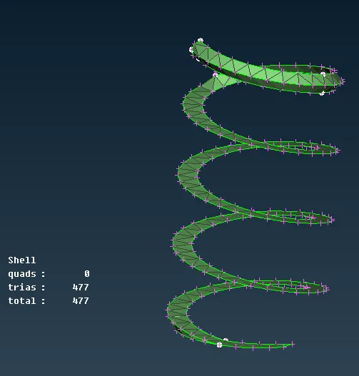
In this case the total cell count obtained is 20770 nos .we can see that the in 3 mm mesh size the outer body is captured well but minor defeature is there.In spring the minimum target length is higher than the spring outer diameter so the spring is deformed for that mesh size.The column and valve head also defeatured due to the target length.
Case 3) Target length =1 mm
- To mesh the geometry we use Mesh > perimeter > Length, In this we use both perimeter and macros and give length =1 mm
- In mesh parameter set target length =1 mm and select element type= Tria( Triangular)
- In quality criteria we give maximum length =2mm and minimum length=0.5 mm
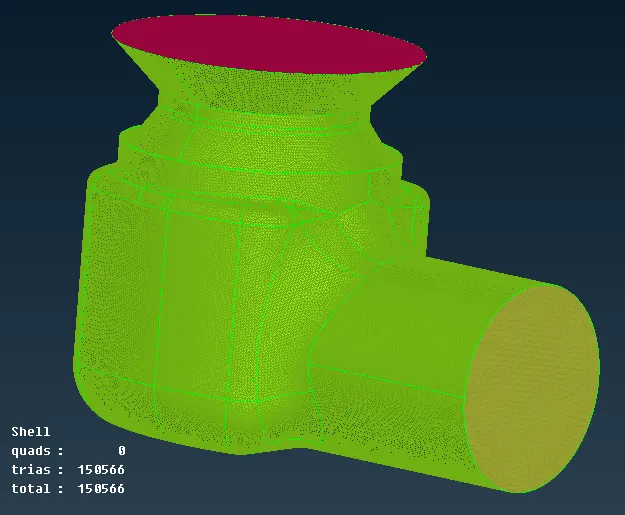
Inlet ,Outlet and body :
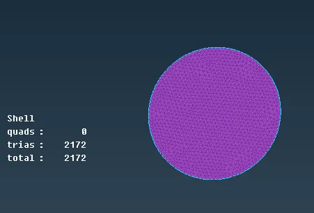
Base surface:
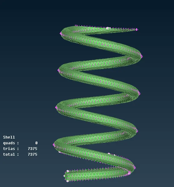
Spring :
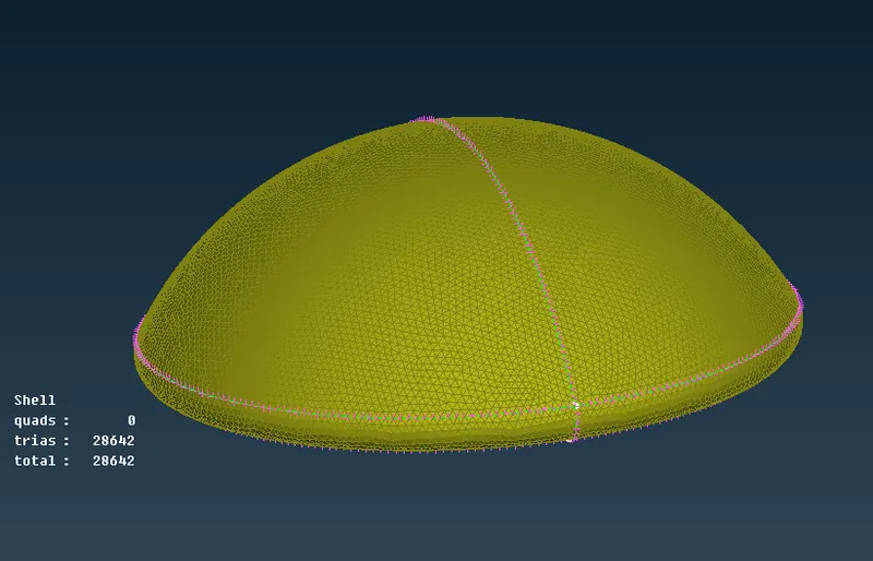
Valve Head :
Column:
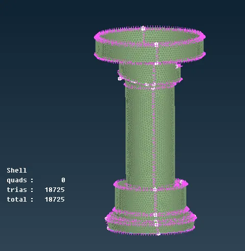
In this case the total cell count obtained is 207480 nos In this case the all geometry is captured very well but cell count is increased .The spring also retain their original shape but small defeature is present .The valve head and column also captured very well in this case.
Results :
- Case 1) Target length = 5 mm Mesh file link is given below :
- https://drive.google.com/file/d/1PgvfX5ZakuRfkNexcErQo-A6mzfMH3Sr/view?usp=sharing
- Case 2) Target length = 3 mm Mesh file link is given below :
- https://drive.google.com/file/d/1jScZHwRDm7gIabuiJfPQqxmUnKwFp2rT/view?usp=sharing
- Case 3) Target length = 1 mm Mesh file link is given below :
- https://drive.google.com/file/d/1uKBzJ_4fI4Gx-GdHyerZsNw4r6LEmQHk/view?usp=sharing
Conclusions:
- From the above 3 cases we conclude that the case of 1 mm target length give a proper shape to the geometry but cell count is increased in this case .
- In order to avoid this we can use different target length individually based on size of the component.from this process we can achieve the best mesh for geometry.