Week 2 Challenge
1.how will assign your circular column
step 1 first open the staadpro software by double click on it
click on new tab and set the units as metric
add the details and create it
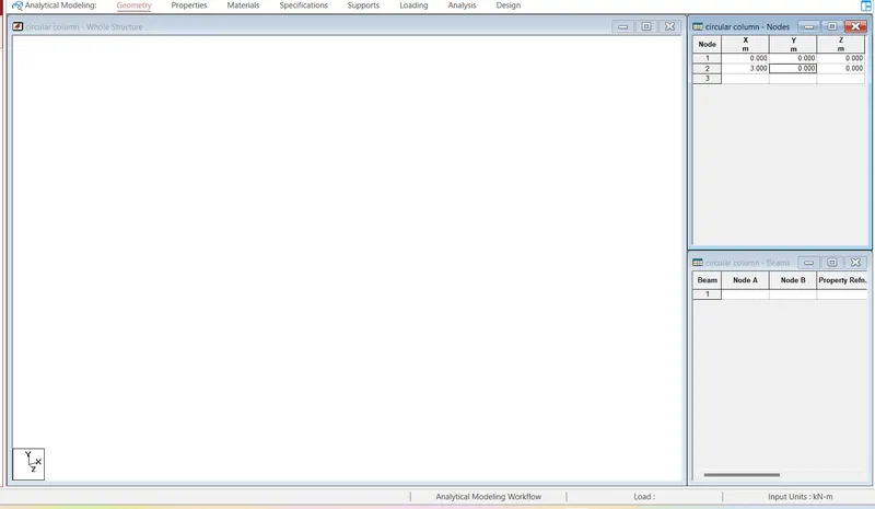
give the first node 0,0,0 of the x coordinate
second node 0,3,0 of the y coordinate points and draw the line
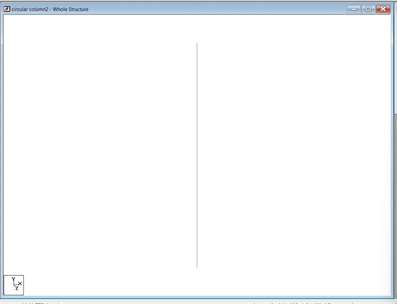
step 2 properties select circular column and set the 0.5 m
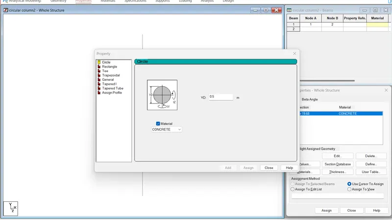
then select the beam and assign the selected beam and click on it
step 3 select the materials in the materrials concrete selct and click on it
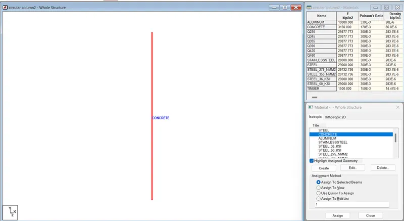
and assign the selected view of the materials and click on it
2. how will you assign unit system to a std model file
we have a 2 option to assign it
we can assign the ystem unit in the beginning stage itself while creating aa model we have a option inthe english or metric we have the first option to assign the units
2nd option we can assign the unit while we creating the model in the middle of the unit system to change the units
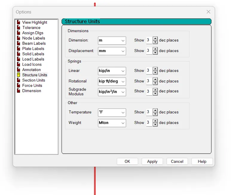
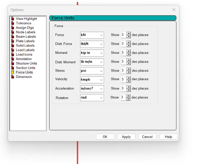
here go to the view tab then go to the display optionthen the option dialog box appears
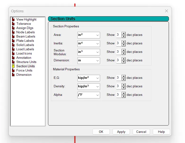
herre we can change the units in the structural units, secction units and force units
section units
force units
3. what are the parameters to be specified while using bay frame option
aim the parameterrs to e specified while using bay frame options
length of the frame
width of the frame
height of the frame
numberr of frame along the length
number of frame along the width
no of frame along the height
4. name few codal standards incorporated in software
iscodes
bscodes
amerrican codes
aci codes
Asce codes
Can /csa codes
5.how will you specify the design compressive strength for a rcc structure
the steps for specify the rcc design is ass follow
first click on analysis and design panel thereselect the design option
when the design option is selected then steel design whole structure dialog box open
then change the design from steel to concrete in the ribbon tab
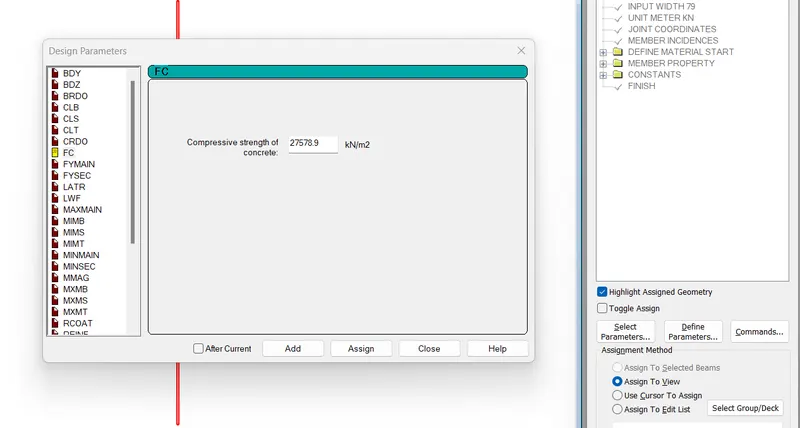
then select the compresive strengrth of the cconcrete the compressive strength of concrete notation fc
if we want to compressive strength ass M30then give the 3000kn/m2
after assigning the value click on addand then click on close
2.state the input steps involved in rcc design
the input steps are as follows
geomentry it is used to mention the node points location and its spacing to create a beam of column
properties herre wee assign the various properties to the model and also we input the dimensions of the sections
materials we assign the materials as concrete beam as column
suppotrs here the end supports are providedd to the beam or column
specifications in the specification we assign the designationthat has to be followedwhile analysing
loadings the loading pattern and loading combinationare necessaryto provide to the beams and columns
analysis after completionn of the above steps and next step to be analysis of the run command
wee are checcking the safety of the building and it also show the followed requirements by using analysis tab
design the final step of the staadpro the design option helps to show the building section and it also provide the reinforcemnt for this design
2.explain d/w fixed and enforced but condition
fixed support condition when fixed type of support condition for those degrres of fredomwhich are to be treated as fully restrined staad assumes the displacement to theknown quantitie whose value is 0hence those degree of freedom are not considered to the stiffness to the matrix the value is not considered
enforced but condition staad assigns aspring stiffnesstanslational stiff springs which are displaced as assign springs as 0 for all the 6 degrees of freedom at such support the displacement are claculated the once which have a stiff spring will end up a having negligible displacemnt and thse which 0 stiffness springs will have a displacemnt based on the structure geomentry properties and loading
3.explain the steps involved in analysisof a model using staadpro sequently
the steps involved in analysis
before the analysisload pattern and load combination should be provide in the model
to perform the analysis go the analysis tab then get the define commands
click on define commands option
after clicking the deffine command optoin then analysis print command dialog box appears
in default the performance analysis is selected select the which type of analysis is necessary for the model
then click on the add button and close the dialog box
after the run analysisby clicking the run analysis command
2.expalin the 2ways of frame work model can be created in a staadpro
the two ways can be created structural fame work model can be created model using staddpro
1. node by node method
2.structural wizard method
node by node method
we can assign the node ass per the archetectural drawing
this nodes are palced by using coordinates
we create a nodes in the geomentry panel
structural wizard panel
structiral wizard is the 2nd modelling the building created in staadpro software
this method is eassier node by node methodbecause it is a automatically method
we have an option to create an truss frames and other structures.
3. different support condition used in stadd pro
pinned support
fixed support
fixed but support
enforced but support condition
multilinear support condition
tension and compression spring
foundation support conditions
Fixed support condition
All the translational and rotational displacement restrained
Fx, Fy, Fz are the translational diaplacements
Mx, My, Mz are the rotational displacements
Pinned support
In pinned support the translational displacements are restrained
The rotational displacements are not restrained (free)
Fx, Fy, Fz are the translational diaplacements
Mx, My, Mz are the rotational displacements
fixed but support condition
to release the trasitional rotational displacement
if we select the transional and rotational displacements then the values is zero
enforced support condition
in this support condition the transitional and rotational dispalcement but it contains spring constant
in default the software takesthe spring constant in this support we cant give the spring constant we want see any spring
mx my mz, are the rotational displacemnt
fx, fy, fz are the transitional displacemnt
4.how will extract the stress stair case distribution slab
the extract the stress stair case distribution slab
first create the nodes of the staircase with proper dimensions
assign the plate as a slab property
after that deffine the load cases and calculate the area load acting on the stair slab
after applying the loadd cases and loadd combination mesh the plate element
then go to the analysis and go to the post processing node
select the plate result ass a plate stress counter
under the stress type choose the appropriate stress type
5. expalin the different ways to views of sfd and bmd
there are 2 ways to view the sfd and bmd
by selecting the beam result and deflection after the post processing
2.graphical method
after completion of the analysis of the softwareitself provide sfd and bmd
first click on the post processing button and click ok
then we get sfd and bmd
to get the values of sfd select the deflection there select teh fx, fy, fz and click on annotate and annotate go to the beam result search the shear force option then click either ends and mid point to get the shear force
to get the values of sfd and bmd of the diagram
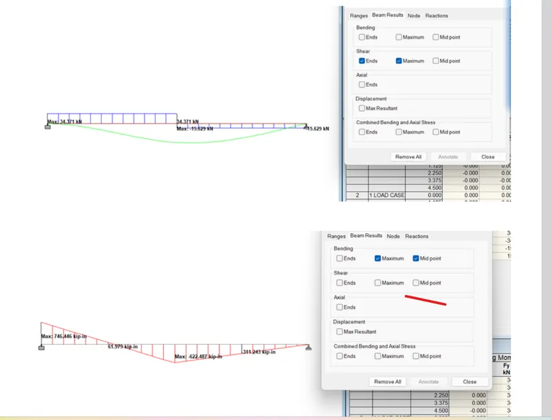
by graphical method to get sfd and bmd values.
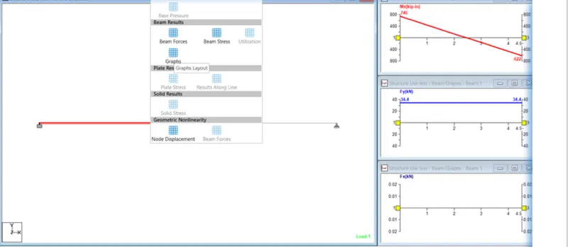
pratical
analyze the following structure elements and validate the results
a simply supported beam
bspan=20m
loadp=50kn
both p located 5m from each support
aim to mmodel the simply supported beam from echa support
introduction
staadpro is one of the most usuable software that are used for analysis and design of structures
staad stands for structural analysis and design
in the software tab support s materials and propertys and loading and analysis for design etc
procedure
open the staadpro software by double click on it
then the start file open it
click on new option then the screen appears
theen give the file name and location of the file want to save
then select ibits as a metric
then click on create
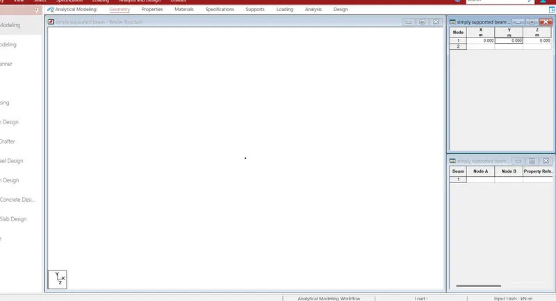
step2
after clicking on the create option the screen will appears
it includes several parametrs like geomentry loading specification property analysis and design materials etc
step3
in this software first we have to provide grids to the beam on the interference
click on the grid ribbon tabthen you will find the grids optionthen click on the below arrow
selecct the beam grid option then the grids will appears
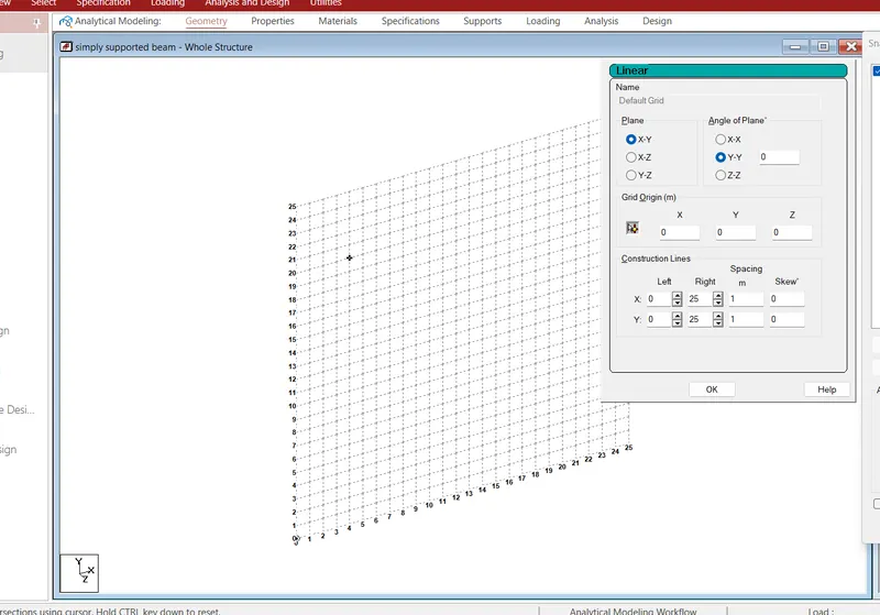
after changing the gridline and spacing
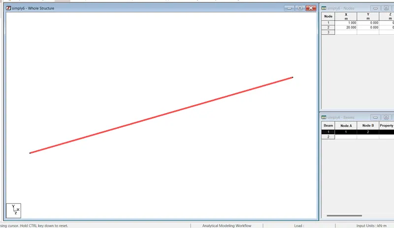
draw the beam having 20m span
step 4
click on proprety tab then dialog box appears
then clickon define box and add the material.
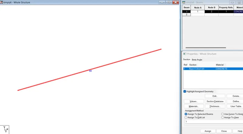
step5
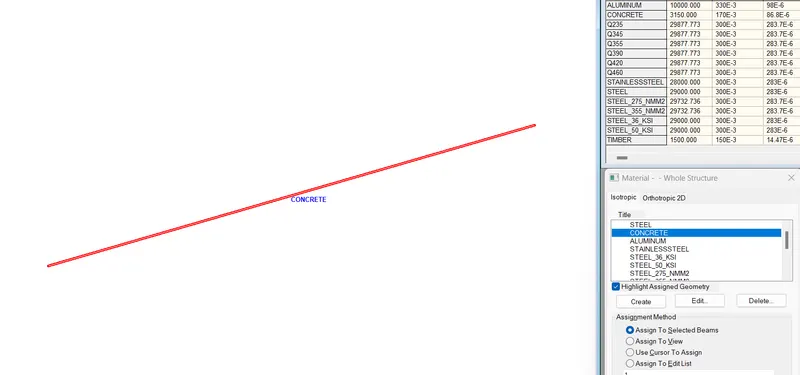
now we have to assign the material to the beam
click on the material tab then the mmaterial dialog box appears
select the concrete and click on the member of the beam
step 6
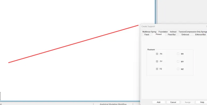
After the assigning the materials then go to the supports
Then the support dialouge box opens then click on create option
Then the create support dialouge box opens
step7
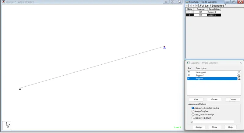
Select the assign option then click on the node which you want to assign the pinned
support
Then click on Esc button.
step8
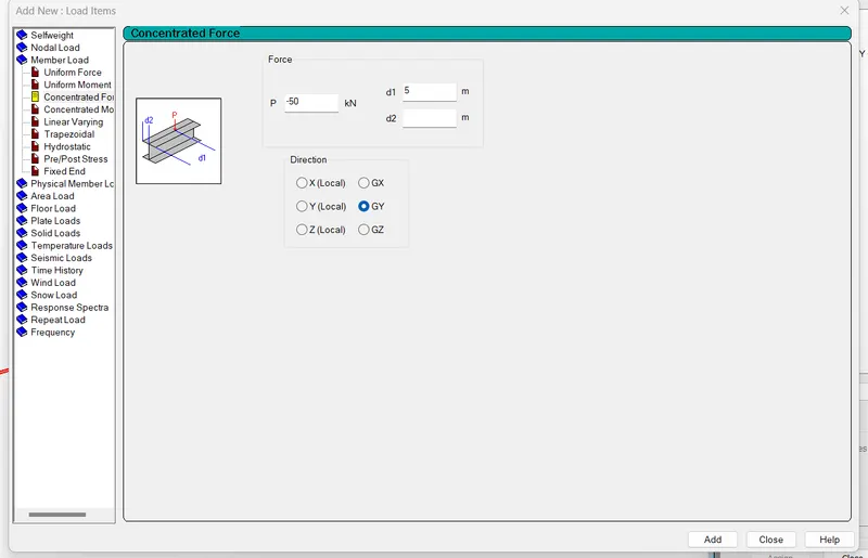
here we need toassign load p=50kn the load p is locatedat 5m from each support
so we are inserting the nodes to assign the load
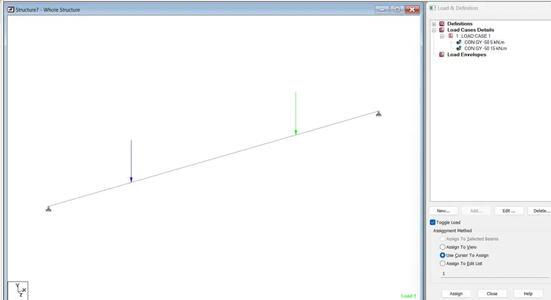
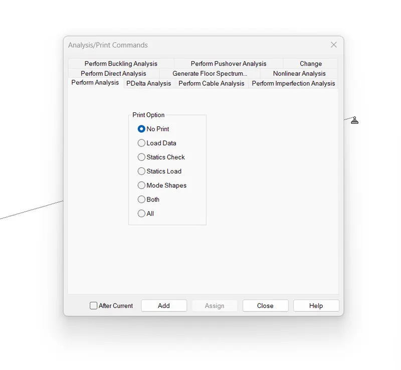
- After assigning the loads we will be doing the analysis, in order to run the analysis set the analysis method and run the analysis just as shown in the below given image:
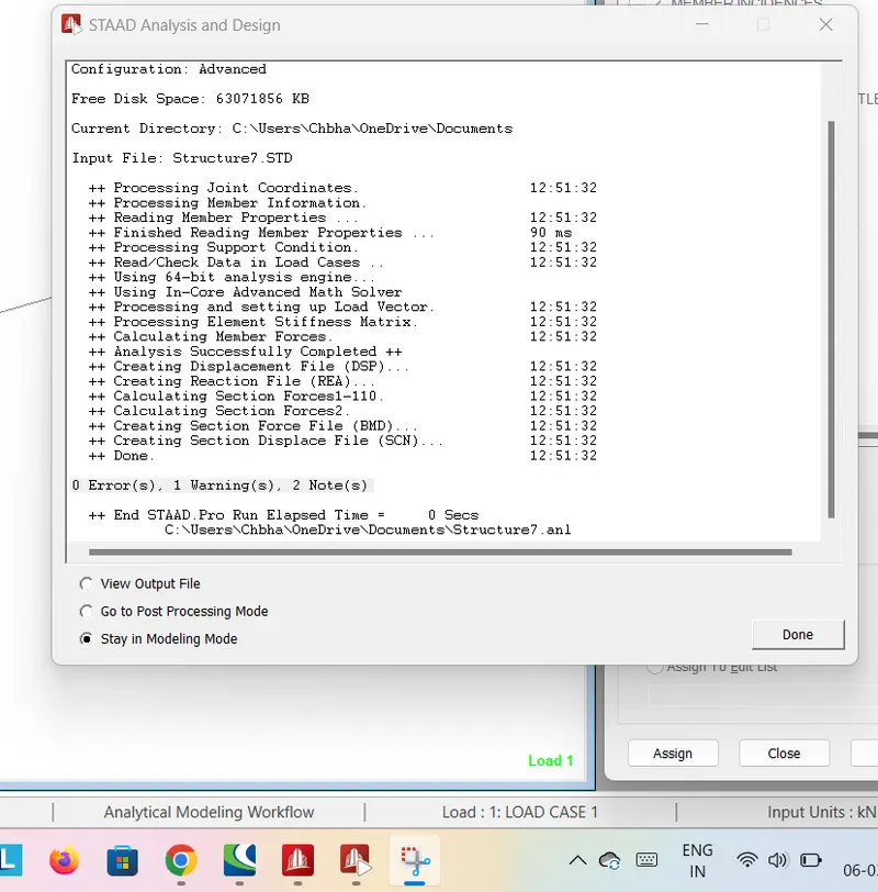
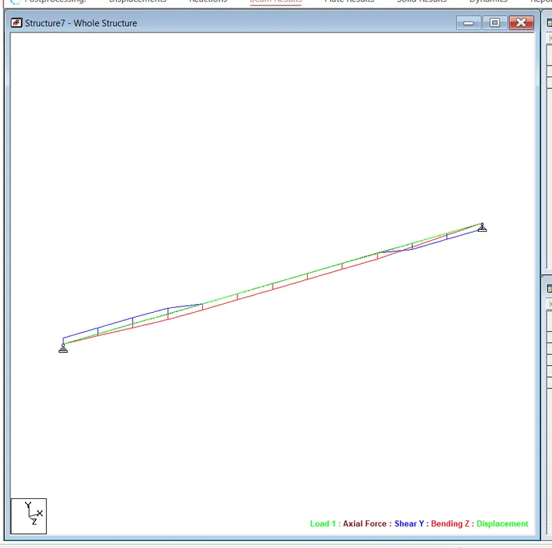
- After doing the analysis go to the post-processing mode and select the load cases and check the SFD & BMD diagrams just as shown in the below given image:
B.Fixed Beam
a. Span L = 16m
b. Uniformly Distributed Load w=9kN/m
AIM:
- To analyse the Fixed beam and to validate the results.
PROCEDURE:
- First of all draw the beam of length 16m. And to draw the beam of 16m use the node-by-node option.
- After creating the nodes now draw the beams just as shown in the below given image
property
select the properrty in the properrty define command
in the command rec select and set the dimensions of the rec
and then click ok and assign it
materials
inthe ribbon tab select materials and click it ok
the materils of concrete and select and assign it beams click it ok
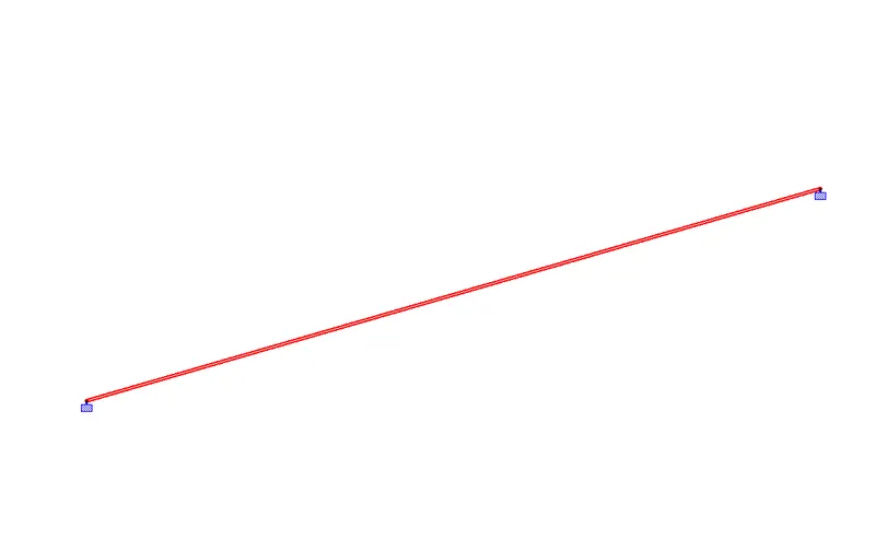
supports
After assigning the material, now we have to assign the support conditions to the beam, its both ends are fixed
- And now assign the point load of 9 KN just as shown in the below given image:
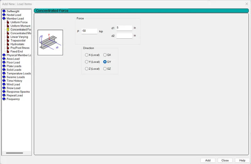
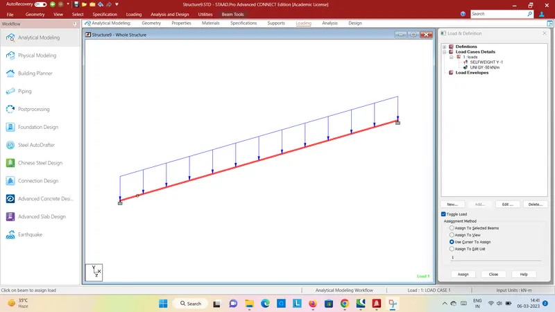
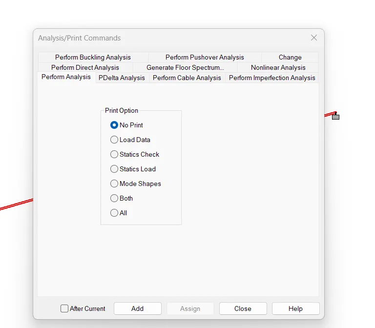
After assigning the loads we will be doing the analysis, in order to run the analysis set the
analysis method and run the analysis just as shown in the below given image
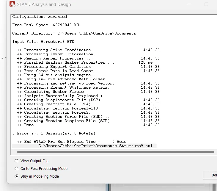
After doing the analysis go to the post-processing mode and select the load cases and
check the SFD & BMD diagrams just as shown in the below given image
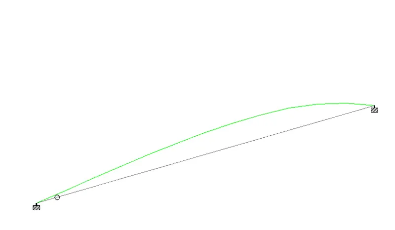
shear force diagram