Week 1 Challenge
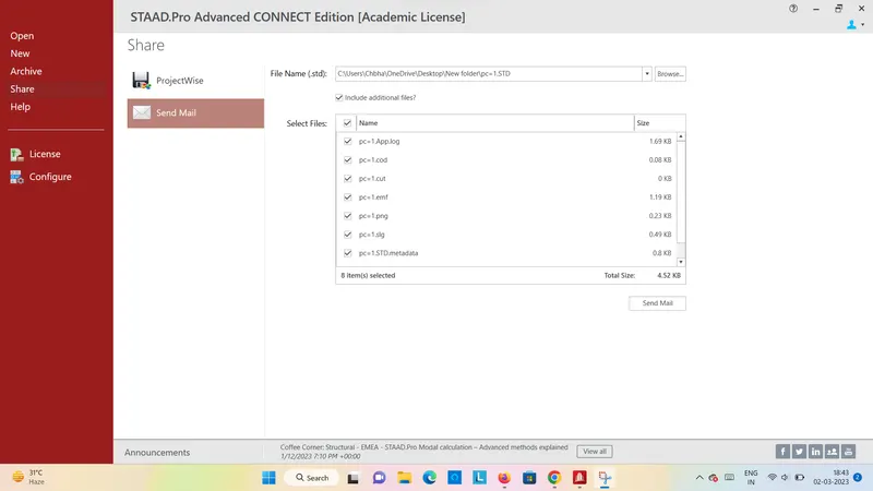
1.write the steps involved to upload a std file using web mail
introduction staadpro is structural analysis and design program observation in the staadpro and it is conneccted new version the rcc structure and steel structure by using the software it using the gui graphics
procedure
open the software staadpro
click the share icon.in
click on send mail
brose the file u want to share
click on send mail
ensure that u are in sign in
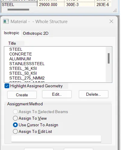
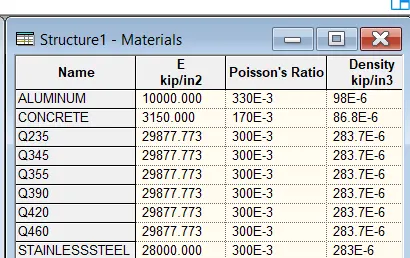
B. the type of materrial used in staadpro
3. it is possible to take the picture of staadpro
go to the menu option>copy picture onthe ribbbon tab option file saved through take picture option are not alreaddy saved picture saved in common picture formats
like jpg pngetc
press tab the navigate arrowkey to edit menu then click on take the picture and using the command line
The physical model is used to draw structural elements as they are physically constructed
The program will then decompose this into an analytical modeling which is passed to the
STAAD.Pro analysis and design engine when you run your model.
The analytical model is a finite element of the structure using physical model interference and analytical model
4. in staadpro physical modeler, the general modelar of the operation is that u first select physical objects and then select to assign the properrties or specification and then assign list of model objects
comparion of model of objects
in this example the assign the profile selection to a set of beams is compared
staadpro physical modelar
select the members whuch we have the same selection
select the selection toolin the assign propertiesgroup on the memberson ribbon tab
selecct the profile and then click ok
analyical staadpro modeling interferance
add the profile u want to use from the selecction data base
select the member property property dialog box
use the cursor to clickon memner property with this property
2.
The program contains a number of parameters that are needed to perform design as
per IS 13920 2016. It accepts all parameters that are needed to perform design as per IS:456
Over and above it has some other parameters that are required only when designed is
performed as per IS:13920 2016. Default parameter values have been selected such that
they are frequently used numbers for conventional design requirements.
parametrs name default name description
1.EUDL NONE equvalant udl span of the beam this load must be unfactored load value by
a facor of 1.2
2.bracing 0.0 brace design
3.in notes 1,2,3 of is 4556-2000
1.0 is the column is unbraced aboutmajor axis
2.0 the column is unbraced about minor axis
3 thecolumn is braced about the both the axis
ELY 1.0 ratio of effective length to actual length of column about minor axis
ELZ 1.0 ratio of effective length to acctual length of a column about major axis
EUDL None Equivalent u.d.l on span of the beam. This load value must be the unfactored
load on span. During design the load value is multiplied by a factor 1.2. If no
u.d.l is defined factored shear force due to gravity load on span will be taken
as zero. No elastic or plastic moment will be calculated. Shear design will be
performed based on analysis result
FYMAIN 415N/MM2 yield stress for main reinforcing steel
fysec 415mm2 yield stress for secondary reinforcing steel
2. tool name description
nodes cursor usually grafically select nodes
i beams used to grphically select beams
plate cursor used to graphically select paltes
solid cursor used to graphically select solids
member cursor member may be user deffined or may be generated automatically using the auto form member tool
to select all the beams defined as a same member using the member cursor just click on the beam the otherr beam also same member name as the selected one will automatically be seleted u may also be physical propertyby dragging a fence area around these physical property
plates and solid cursor used to grsphically both teh plates and solid elements
text select text add the comments and select the size of the text and modifying using the text comments
loads use to modify any load applied on the modelbydouble clicking itwhen seleccted the mouse ppointer changes to load edit cursor
4.simply supported condition on staddpro
go to the suppirt commandin the tool palet command
click on create support command
there we can get option like pinned fixed and fixed but
5. name any five topics that would u like dbr
DBR design basics report
to take up a project from the scratch end its needs
to specify data and complete data received and analysis of designof structure element
it contains the assumptions and specifications todevelop the project
it will avoid to develop the scope it can creepthe project schedule and budget overness
contains the general column drawing
contains the project planning
length
The body of the report should be no more than ten double-spaced pages. Detailed design
work, drawings, diagrams, engineering analyses, vendor part descriptions (e.g., gears,
bearings), parts lists, and references should be referred to in the body of the report and
then included as attachments.
2.purpose of the report
the purpose of the report is to describe all asspects of your mechanical designproject in a consie of the manner
audience
assume that your report read by the suprrvisor and other deisgn by manufacturing engineer working on this project
title page
organisation
include the title of the report your name and date of the submission
the concept
using a neat hand sketch cad drawing describe the final conceptial design of your project
3.name the structural system used instaadpro expalin each system
structure system geomentry loading deform joint
space 3D 3D 3D ANY
PLANE 2D 2D 2D any
frame 2D PERTOXZ PER TO XZ ANY
TRUSS 3D 3D 3D PINNED
2.explain ecah system used i staadpro software
they are 2 coordinate system in staadpro
global axis global axis is fixed in the coordinate system
local axis local axis is variable
this is used for orientation of the beam and load variable
3.elaborate dbr and its uses
dbr means design base report
to take up a project from the search end to itsneed
to specify data andcompile data received and analysis and design of structural element
it contains the aasumptions and development of the project
contains the general column of the drawing
contains the project planning
4.explain the diffrent analysis option used in staadpro
explain the d/w fixed and fixed but condition
in fixed conditionthe node and the end conditionare fixed and restrined with the fx fy and fz
and the moments are also retrined
in fixed but condition the nodes are fx and mz are released as it is horizontal rolled support
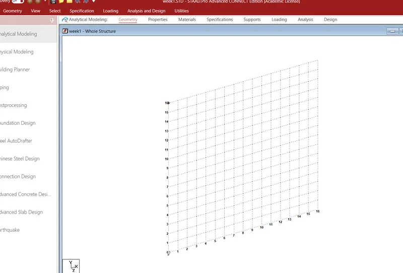
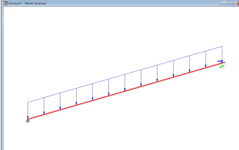
aim create a staadmodel with the following specification
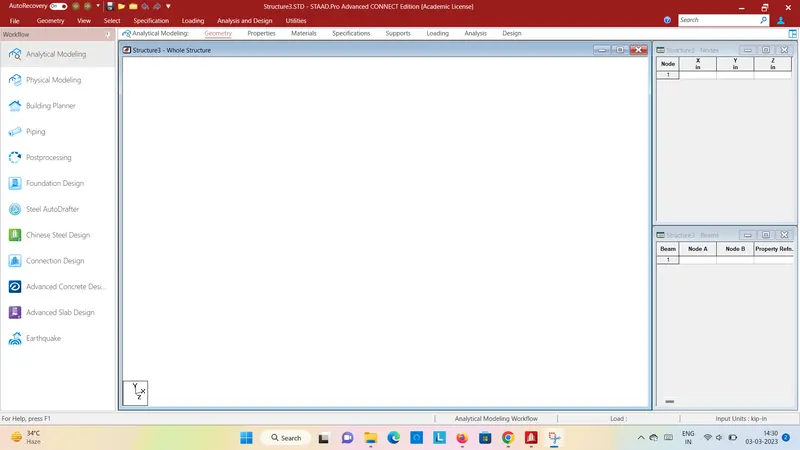
grid dimensions are be taken 1m in x and y 16m span
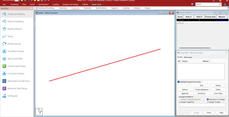
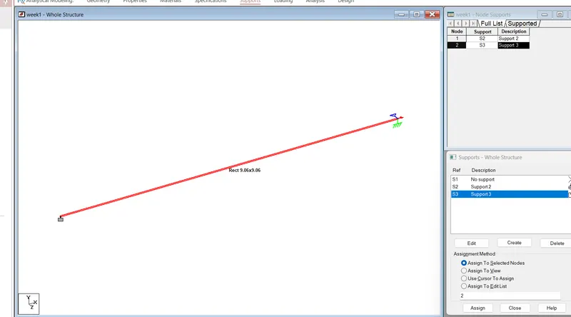
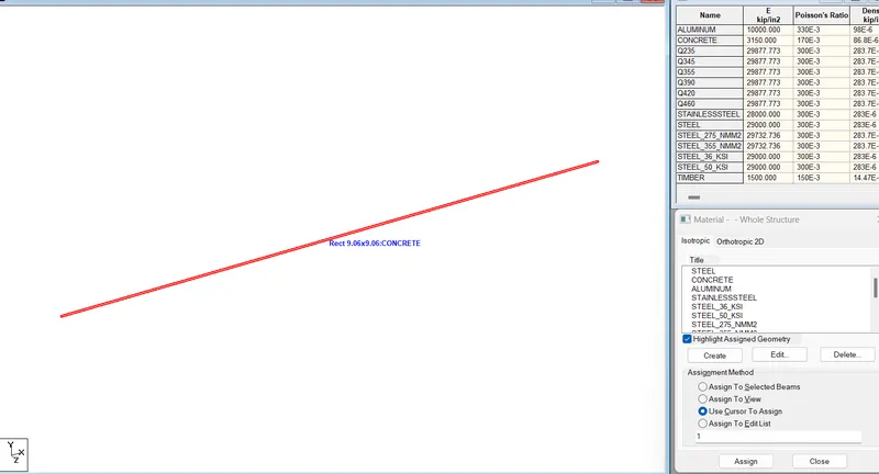
b. Support : Fixed on one end and Roller support(Horizontal) on the other end
c. A point load of 50 kN at the mid-point
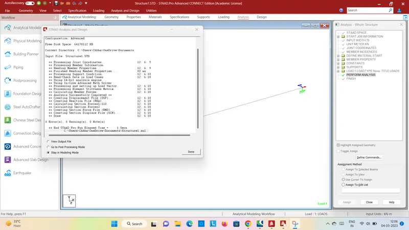
d. Draw SFD and BMD using software
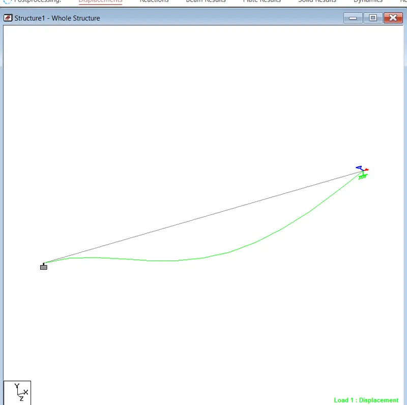
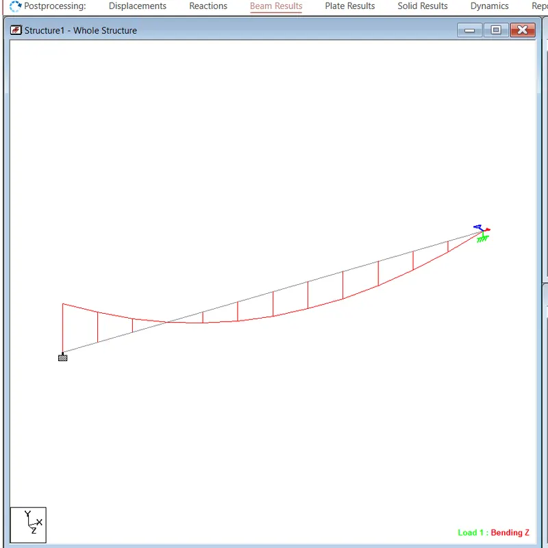
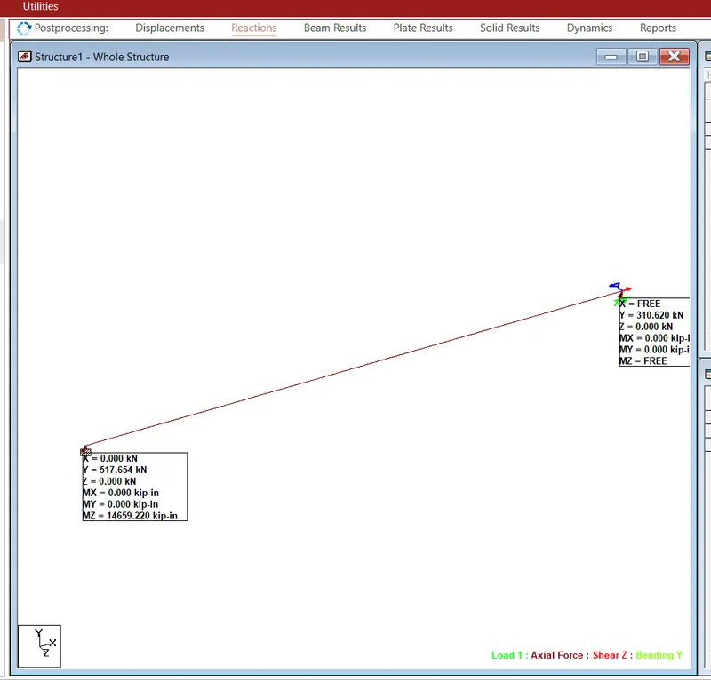
result the total shear force and bending moment is completed