Week 2 Challenge
CHALLENGE 2
A) Assign circular section to column.
- After creating a column using grid system or any other method, go to property and select define parameter and select circular section, specify the value and click add.
- After creating a circular section to the property using column cursor option to select the column and select the assign the selected column to assign the column section.
B) Unit system in staad.pro
- To assign the unit system in staad pro, specify units in model info from the creation of new project.
- To change the units, click file icon and go to setting and select display options and select structure units to specify
C) Parameter in Bay Frame
- Length, breadth, height.
- No of bay along length.
- No of bay along breadth.
- No of bay along height.
D) Codal standard in staad pro
For steel
- IS 800 - 2007.
- SP – 16
- AISC 360-16
- BS 5400
- ASME NF3000 2004
For concrete
- IS456
- BS8007
- ACI 318 2004
- IS13920 2016
For aluminum
- Aluminum US
For Timber
- ECS
- AITC 1994
E) Assign compressive strength in model
- After analyze the model or structure in staad pro, click design tab and specify concrete in design commands.
- Select the IS456 code in current code.
- Click select parameter to specify the data to add.
- Click define parameter and click ‘FC’- compressive strength of concrete and give the values and select add.
- Click the created FC use assign to view option to assign the compressive strength of concrete.
2) A) Input steps involved in RCC design
- Design using codal provision as per required standard.
- Design parameter addition like compressive strength, yield strength, main bars, spacing, clear cover, distributed rod.
- Design parameter assign using assign to view option.
- After the above steps click advanced RC design on left side icon.
- Specify the design setting, reinforcement settings, shear force, bending moment diagram, etc.
- After the all the specification has applied click design to design the Rcc design.
B) Fixed and Enforced support
- Fixed and Enforced support are same restrained condition.
- But in loading case enforced support can be support displacement and Direction and Displacement can be changed in nodal load.
3) A) Step involved in analysis of model in STAAD PRO
- Creation of geometry.
- Property and material assign.
- Support assign.
- Load assign.
- After loading, click Analysis tab specify type of material to analyse in design command.
- Specify the current code as per standard.
- Select define command and select perform analysis to add.
- After adding all necessary details click run analysis option on ribbon to analyze.
B) Creation of model in STAAD PRO
- Grid table method- It is method that model have irregular shape and regular shape can be created. In grid system we can be create beam grid, plate grid, quadrilateral grid to make structures.
- Structural wizard method – In this we create a model using prototype that are inbuilt in the staad pro. We can specify model type and select type of structure and specify the value to create a structural model.
C) Support condition in staad pro
- Fixed condition – It has support fixed at the end. It does not move from one place to another. If the two end of beam are fixed it acts like simply supported beam. If one end is fixed and other end is free it acts like a cantilever beam in staad pro. In fixed support condition all the transitional and rotational moment are restrained by staad pro.
- Fixed but condition – In this condition we can release the spring by specify it and define spring condition in staad pro.
- Pinned condition – In this condition transitional force are restrained we can specify the rotational moment about the axis.
- Enforced condition – In this condition the all the force and moment are restrained. But in loading condition we can apply nodal displacement.
D) Stress distribution in staircase slab
- Create the staircase model using nodes in geometry panel.
- Run the analysis.
- After Analysis, go to Postprocessing and select load combination and click on plate results.
- Select plate stress contour, select load case, select stress type, check Max Absolute stress and check Major Principle stress.
- After apply the above will get stress distribution diagram in staircase slab.
E) Graph view of SFD and BMD
- After Analysis, click on Result tab.
- Go to view Result palette.
- Check SFD and BMD by click on SFD and BMD tool for separate view.
- If we want combined view click on Result Tab, Go to view Results Palette and click on layout.
- Click on graph to view SFD and BMD.
1) SIMPLY SUPPORTED BEAM
AIM
To create a simply supported beam and fixed beam model and assign property as per given detail in staad pro.
PROCEDURE
- To create new file by specify model info and project info on the staad pro connect new file tab.
- To specify the units and click create project, after enter all the detail click geometry tab and create node using nodal table method.
- After creating node, create beam using add beam option.
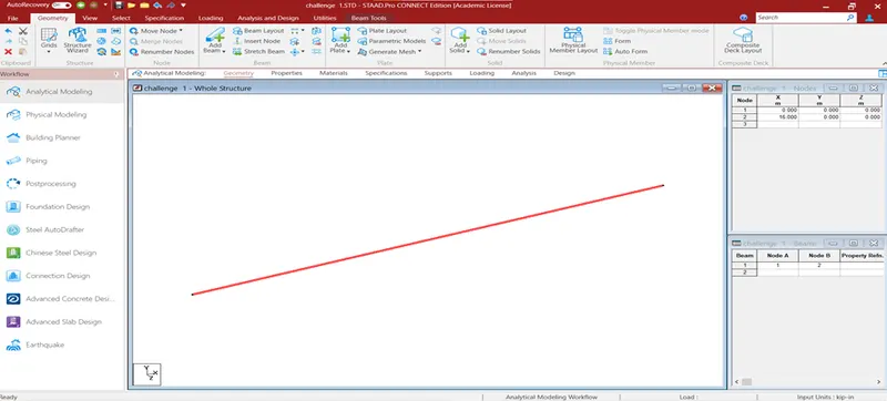
- After creating geometry, click property to assign the property for beam by using define parameter option.
- After assigning property, click material tab to assign the material.
- After assign the material, click support tab to create a support. After creating the support assign the support to the beam nodes.
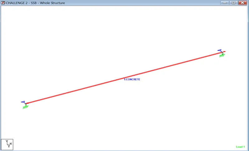
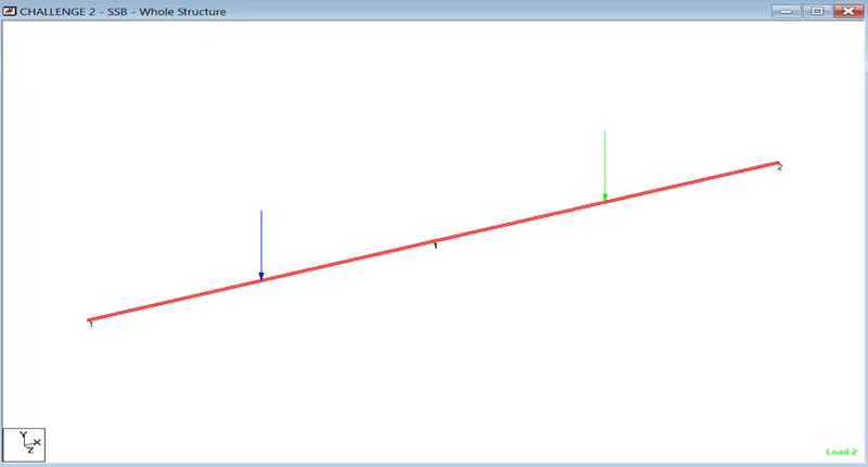
- After assign the support, click load tab and select load cases to add new load. Click new load data and click add to create type loads. After create the load on load case specify load for beam using assign the selected beam option.
- After assign the load, click analysis tab and click create command option. Click run analysis option analysis tab system will check and run the analysis.
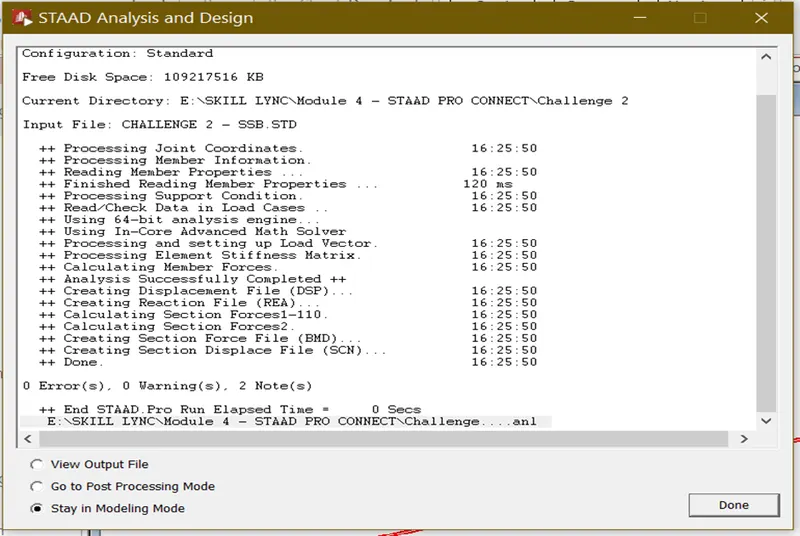
- After analysis done, click the post processing view to view bending moment, reaction drawing.
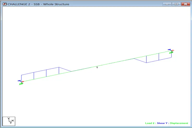
Shear force diagram
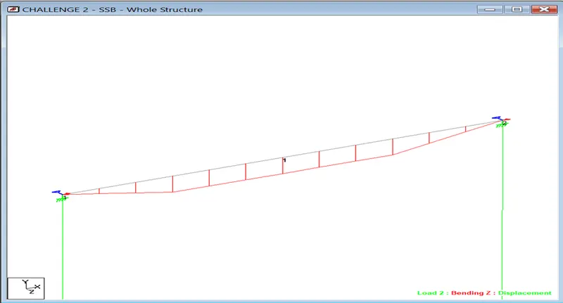
Bending moment diagram
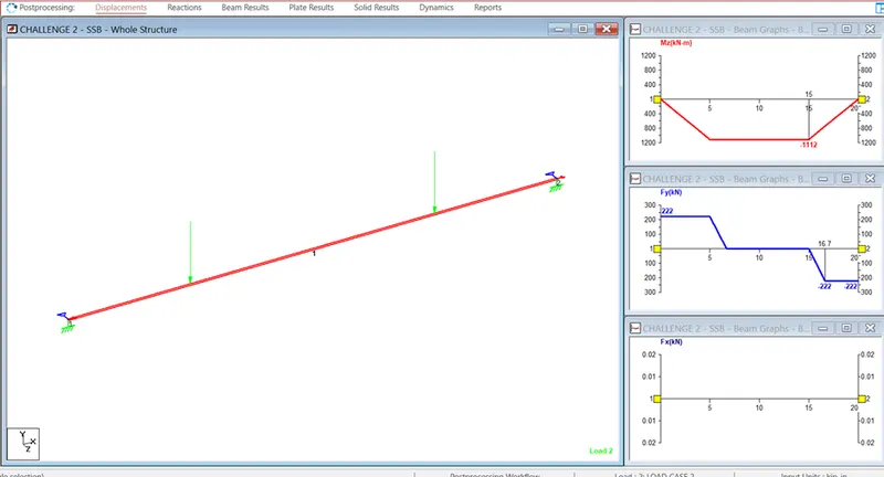
Graphical presentation of SFD & BMD
RESULT
The creation of simply supported beam model and analysis of beam model as per given data has been done.
2) Fixed beam
AIM
To create a fixed beam model and assign property as per given detail in staad pro.
PROCEDURE
- To create new file by specify model info and project info on the staad pro connect new file tab.
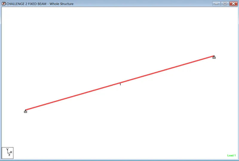
- To specify the units and click create project, after enter all the detail click geometry tab and create node using nodal table method.
- After creating node, create beam using add beam option.
- After creating geometry, click property to assign the property for beam by using define parameter option.
- After assigning property, click material tab to assign the material.
- After assign the material, click support tab to create a support. After creating the support assign the support to the beam nodes.
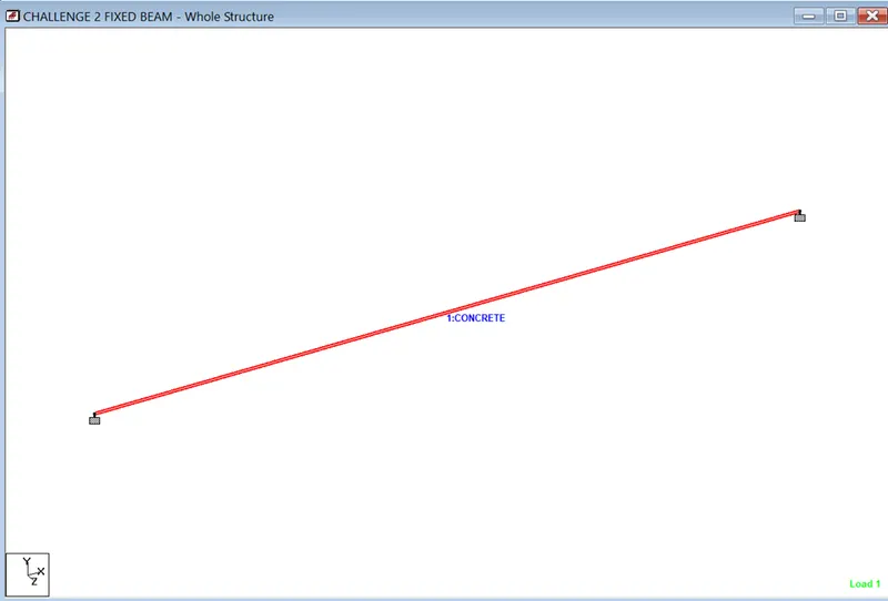
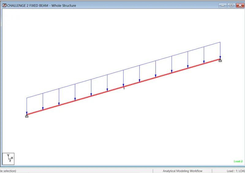
- After assign the support, click load tab and select load cases to add new load. Click new load data and click add to create type loads. After create the load on load case specify load for beam using assign the selected beam option.
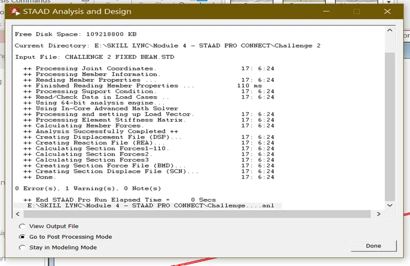
- After assign the load, click analysis tab and click create command option. Click run analysis option analysis tab system will check and run the analysis.
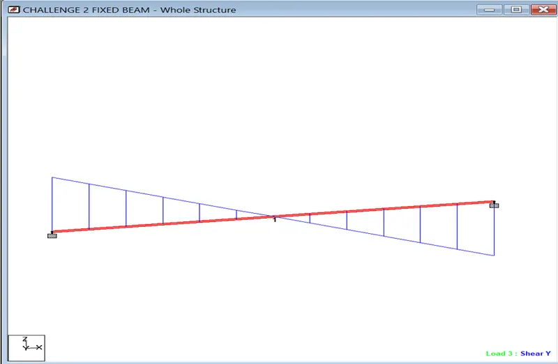
- After analysis done, click the post processing view to view bending moment, reaction drawing.
Shear force diagram
Bending moment diagram
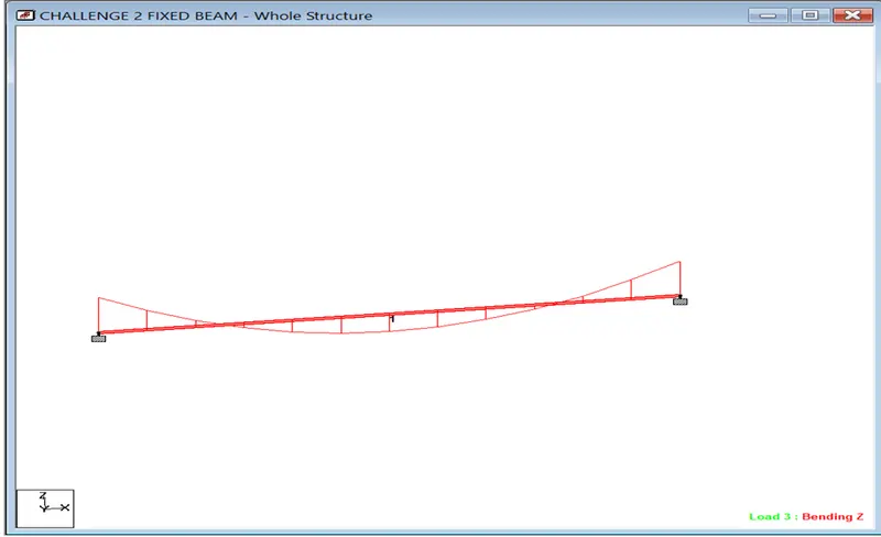
Graphical presentation of SFD & BMD
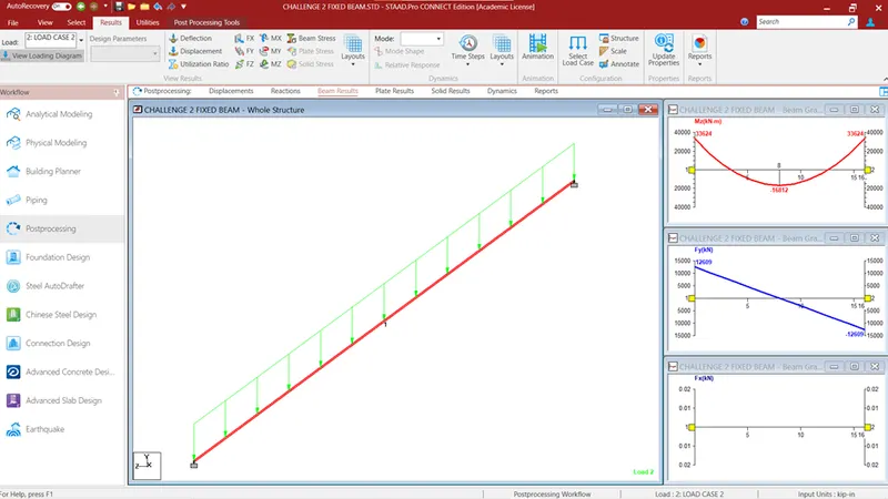
RESULT
The creation of Fixed beam model and analysis of beam model as per given data has been done.