Week 2 Challenge
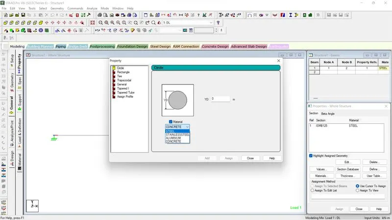
ANS 1(1): Assigning Circular section to column:
Modeling tool contains GENERAL tab preceded by PROPERTY option enclosed within it.
Then, a pop up window would open and select DEFINE option for assigning user based properties to the model.
--------------------------------------------------------------------------------------------------------------------------------------------------------------------ANS 1 (2):
Assign Unit System to a stad.model file:

Unit System may be defined either on commencement or inbetween the modelling process using the two tabs marked in the above screenshots.
Where Left one represent unit dimension window while Right Tab represent Unit dimension change.
-----------------------------------------------------------------------------------------------------------------------------------------------------------------
Ans 1 (3):
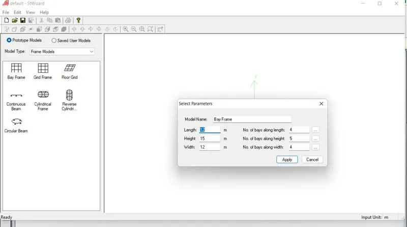
Parameters to be assigned while using BAY FRAME option:
-----------------------------------------------------------------------------------------------------------------------------------------------------------------
Ans 1 (4):
Codal standards incorporated in STAADPRO software includes:
| STEEL | CONCRETE | TIMBER |
| IS 800 | ACI 318 | AITC 1994/1984 |
| IS 800 2007 (LSD/WSD) | AIJ | CSA086-01 |
| IS 801 | AS 3600 | EC 5 |
| IS 802 | IS 13920 | |
| SP 16. 13330. 2011 | IS 456 | |
| AISC 360-05/10 | SP 63. 13330. 2012 | |
| AASHTO (ASD/LRFD) |
-------------------------------------------------------------------------------------------------------------------------------------------------------------
ANS 1 (5):
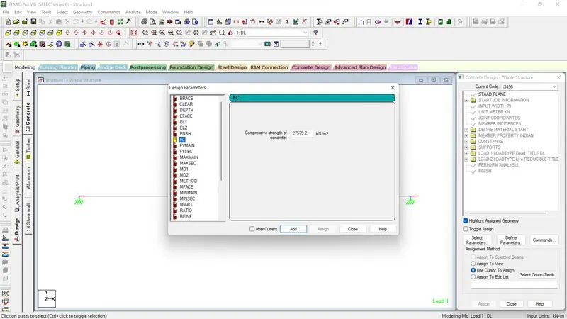
Design Compressive Strength for a RCC section can be specified during the post processing phase using DESIGN tab option in modelling tool.
1. Select & assign the material to the modelling element followed by Codal selection in the pop up window as described in screenshot below.
2. Select Define Parameter Tab from the pop-up window
3. Select FC option for defining the compressive strength of beam.
---------------------------------------------------------------------------------------------------------------------------------------------------------------
ANS 2 (1):
Input Steps involved in RCC Design:
GEOMETRY
GENERAL (PROPERTY(Eiher user-deign or predefined), SPECIFICATIONS, support, Loads & combination, Material)
Analysis & Print(Various analysis like Linear/Non-linear Analysis, p-delta, pushover analysis etc.)
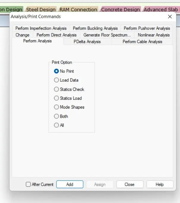
Design(Define Parameters, commands[Checks, beams, column, Takeoff, Select option]).
---------------------------------------------------------------------------------------------------------------------------------------------------------------
ANS 2 (2):
| FIXED SUPPORT | ENFORCED SUPPORT |
------------------------------------------------------------------------------------------------------------------------------------------------------------------
ANS 3 (1):
Steps involved in analysis of a model using STAADPRO sequentially:
1. First model the structure using GEOMETRY tab either by coordinate system(user-defined) or run structural wizard tool (prototype/ predefined)option.
2. Use GENERAL tab to define and assign various properties to the element such as:
- Property(dimensions & shape).
- specification about various elements like Nodes, Beam, Plate.
- Support (FIXED, PINNED, ENFORCED, Multilinear spring, tension/compression member )
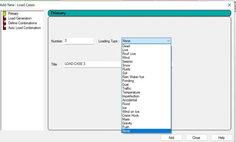
- Load & combination (based on various categories like dead, live, wind, snow, seismis as shown below )
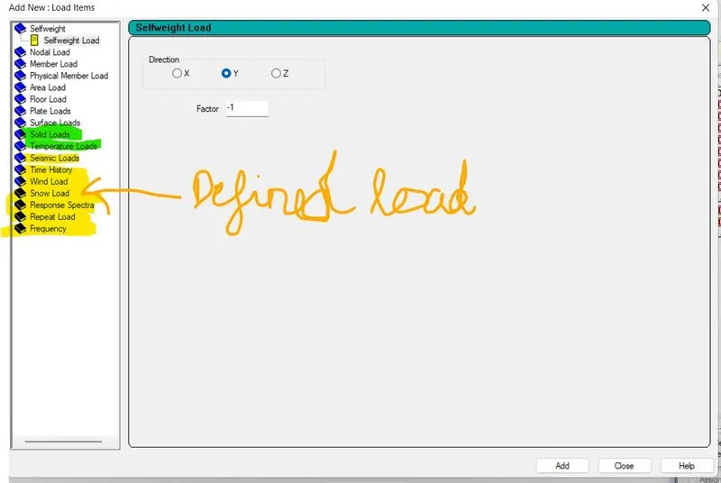
Each above mentioned load is assigned to various members, out of which loads marked in yellow color are defined before assigning to individual members in DEFINATION tab while rest of the loads are assigned to various elements based on nature of loading i.e.
(Selfweight, Nodal, Member, area load, Floor load, plate & surface load etc.)
3. Each Element is defined by the material using MATERIAL tab within GENERAL option.
4. Analysis option is chosen based on needs.
-------------------------------------------------------------------------------------------------------------------------------------------------------------------
ANS 3 (2):
Model can be ceated in two ways:
1. Using Coordinate system
2. Using RUN STRUCTURAL Wizard option (Truss, Frame, Plate/surface, Solid model, Composite model, VBA-Macro Model).
-------------------------------------------------------------------------------------------------------------------------------------------------------------------
ANS 3(3):
Different support system in staad pro model are:
Fixed, fixed but, pinned, Enforced, enforced but, Tension/Compression only springs, multilinear springs, inclined, foundation etc.
-------------------------------------------------------------------------------------------------------------------------------------------------------------------
ANS 3 (4):
--------------------------------------------------------------------------------------------------------------------------------------------------------------------
ANS 3 (5):
Ways to view SFD & BMD in STAADPRO are:
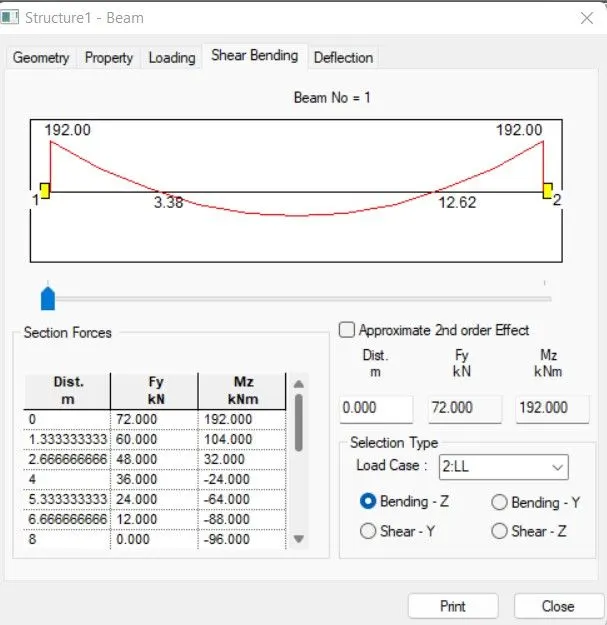
1. After Analysis & Print option is defined, Double click on the element whose SFD & BMD is to be calculated as described in below screenshot.
2. In post processing mode, we may define the elements in GRAPHS(here photo is snapped using camera option available in software).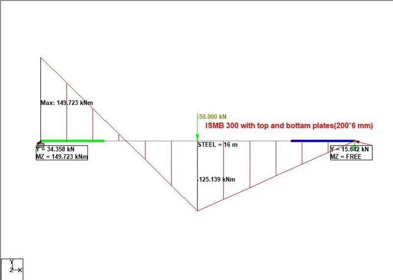
3. Using option available in taskbar as described in below snapshots:
