Week 2 Challenge
1.
- How will you assign Circular section to column?
- Open STADD Pro Software.
- Create two nodes in vertical direction since it is a column.
- Then go to properties and create new property.
- Select circular and give the diameter.
- Then press ok. The property will be created.
- Then select the property and use curser to assign option.
- The click the start and end point.
- Thus the circular column is created.
- How will you assign Unit system to a .std model file?
- Open STADD Pro. Then Create a New file.
- In that we have English and Metric unit system.
- We can use the unit system by using this.
- We can give necessary unit system and create the model.
- What are the parameters to be specified while using “Bay Frame” option?
- We can create the model by using default structural layout option.
- In this we can create a building model by using Bay Frame. Option.
- We need to provide the data’s of Length of building, Breadth of building and Height of building.
- Then how many bays in Length wise, how may bays in Breadth wise and How many bays in Height wise.
- Then we click ok. The Structural model is ready.
- Name few codal standards incorporated in STAAD Pro software.
- STADD offers Default Codal Provisions.
- We have IS 456 2000 for Concrete Structure Design.
- IS 800 2007 for Steel Structure Design.
- It also considers IS 1893 2016 for Seismic Design of Building.
- How will you specify the design compressive strength for a RCC section?
- Once Analysis is done go to Design and click on Design Parameters.
- Then click on Fck in the Left Side of the Tab.
- Then enter the compressive strength of the Concrete.
- Then click ok. Then click on the Fck value and select assign to view.
2.
- State the “Input” steps involved in RCC design.
- Once the Analysis is done. Then go for the Design of RCC elements.
- Select the Code for Design as IS 456.
- Click on Design parameters. Then Provide the Compressive Strength of Concrete and Yield Strength of Steel.
- Then we also have different design Parameters like Minimum Reinforcement, maximum Reinforcement, Minimum Cover, Maximum Cover etc.
- Then go to commend and Select design Column.
- Then select the Created parameters and assign it.
- Then run analysis. Then check the results, we can see the Cross section and Minimum steel required, etc.
- STADD also have Default Advanced Concrete Designer tab to Design the Concrete Elements.
- In this we can get the detailed calculations, Cross section of column, longitudinal Section of column etc.
- We can also generate the Result of the Analysis.
- Explain the difference between Fixed and Enforced support condition in STAADPro.
- Fixed support where all the translational and Rotational Movement are restrained.
- But in Enforced, All the Translational and Rotational Movement are Restrained but it can allow minimal amount of displacement.
- We can define this minimal displacement in the Loading.
3.
- Explain the steps involved in analysis of a model using STAAD Pro sequentially.
- Open STADD Pro Software. Click on New and give the details of the Project.
- Then Use Metric system and click on create.
- Then go to geometry. Then use nodes to create nodes and use Translate and repeat to copy the nodes.
- Then use Add beam to add beams and columns abd Add plate for slabs.
- Then go to Properties and create the geometry of Column and Beam.
- Then Assign the Beams and Columns.
- Then Material and Create material and Assign it.
- Then go to support and create supports and assign it to the bottom of Columns.
- Then Create loads and Load combinations.
- Then Assign created loads to the Beams.
- Once all assigned.
- Then go to Analysis tab and create perform analysis and then run analysis.
- Once analysis is completed then go to design tab and give Properties of material and Assign it to the material.
- Then run analysis.
- Thus we can extract the result of the Beams and Columns.
- Explain the two ways in which a structural framework/model can be created in STAAD Pro software.
- A structural frame Model can be created by using Two ways.
- Nodel method and Structural layout Method.
Nodel Method
- In nodel method we create the nodes where ever we required by using translation and repeat option with Distance and Steps.
- Then we use add beam option to add beams in between the nodes.
- We select the beams and use Translation and repeat and We place the beams with required distance and bays.
- Similarly, we can create columns for the same.
Structural Layout
- Nodel method will take time to create. If the building is Similar and in stories and Rectangular we can Use Bay frame in Structural layout.
- Click on it and We need to provide the data’s of Length of building, Breadth of building and Height of building.
- Then how many bays in Length wise, how may bays in Breadth wise and How many bays in Height wise.
- Then we click ok. The Structural model is ready.
Elaborate the different support conditions in STAAD Pro.
- We have Different Support Conditions in STADD Pro. They are
Fixed Support
Pinned Support
Fixed But
Enforced
Enforced But
We also Have Multilinear springs, Tension/Compression only Springs.
- How will you extract the stress distribution for a staircase slab?
- Once Geometry is created and Support and Loading Condition is Provided for The Staircase.
- Then go for Analysis and Run the Analysis.
- Once Analysis got completed. Go for post processing and for Plate result.
- Then check for Plate stress combination for Load Combination.
- We will have the maximum and Minimum Stress values and the colour for different stress also can be seen.
- We have different stress types we can toggle with different types and can view the stress variation in the stair case.
- Explain the different ways to view SFD & BMD in STAAD Pro.
- Once the Analysis is done go to post processing and click on beam result.
- Then click on Fx and Fy to view the Shear force and Mz to view the Bending Moment Diagram.
- We can see the Maximum values by annotating the Values of Shear force and Bending moment Diagram.
- We can also see the Bending Moment and Shear Force diagram I the Report by right clicking the beam.
Practical
- Analyze the following structural elements and validate the results
A. Simply Supported Beam
a. A Simply supported beam with two point loads symmetrically placed
b. Span L = 20m
c. Load P = 50kN each
d. Both P located at 5m from each support
Aim
To Analyse the Simply Supported Beam with two point loads Symmetrically Placed.
To Take the Shear Force and Bending Moment Diagram and Reinforcement Details for the Beam.
Procedure
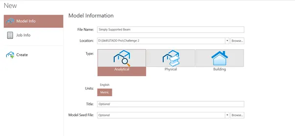
- Open STADD Pro. Click on New model.
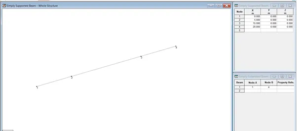
- Then use Grids, Beam Grids and give start point as 0,0 and End as 20m,0
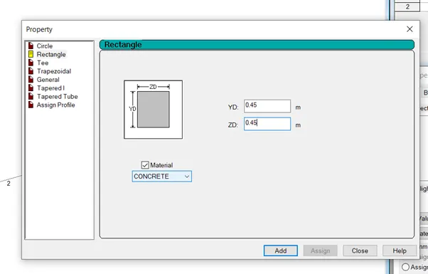
- Then properties create new.
- Rectangular beam of 450 x 450 then give material as Concrete.
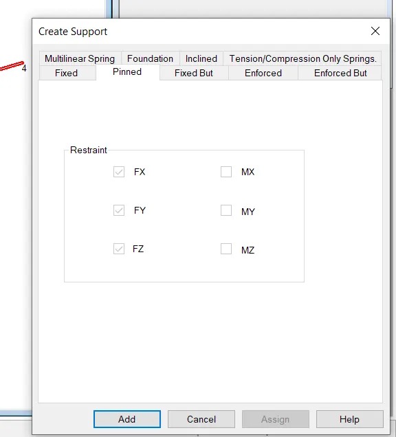
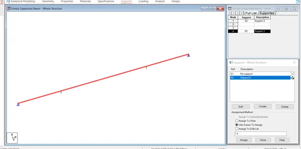
- Go to Support and then create Pinned Support.
- Then Assign supports to both ends respectively.
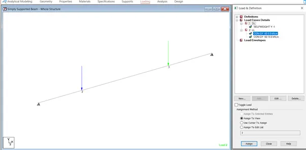
- Then give load. Create load case give live and add.
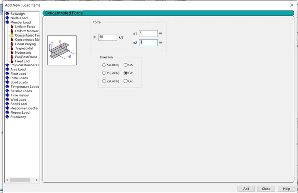
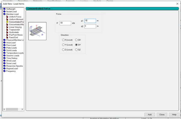
- For placing Loads create two nodes in 5m and 15m distance.
- Then edit load case give concentrated load of 50KN.
- Then use courser to assign and click on created nodes.
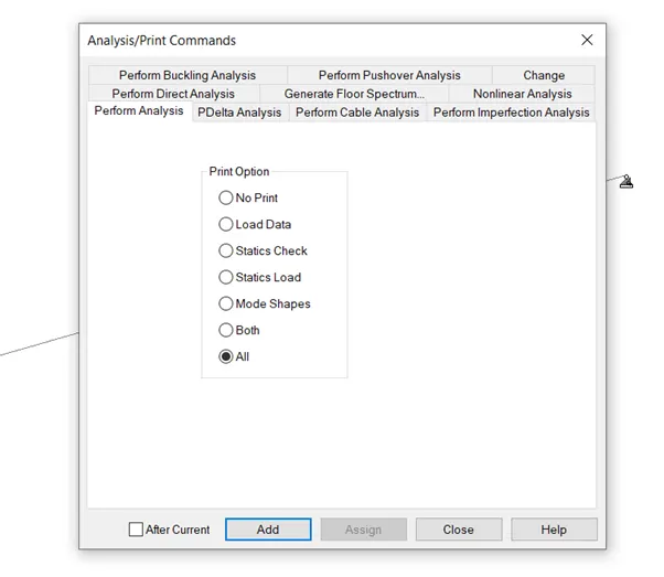
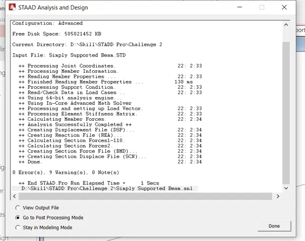
- Then go to analysis and perform analysis and then run.
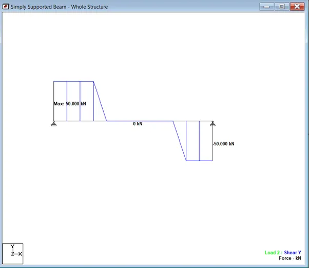
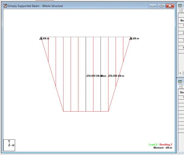
- Then take the output and shear force and bending moment diagram.
- Then go to design and provide design Parameters as Fck 25N/mm2 and Fy as 415 N/mm2
- Then run the Analysis and right click on the beam to get the result.
Input
Output & Result
Shear force and Bending Moment Diagram
B.Fixed Beam
a. Span L = 16m
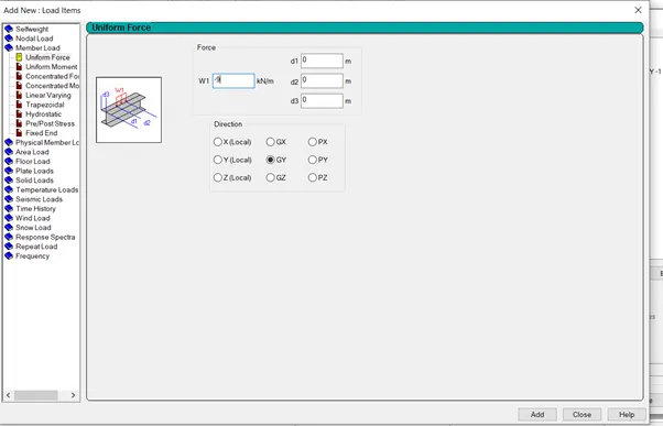
b. Uniformly Distributed Load w=9kN/m
Aim
To Analyse the Fixed Supported Beam of 16m Span with Uniformly Distributed Load of 9KN/m
To get the result of Bending moment and Shear force diagram.
Procedure
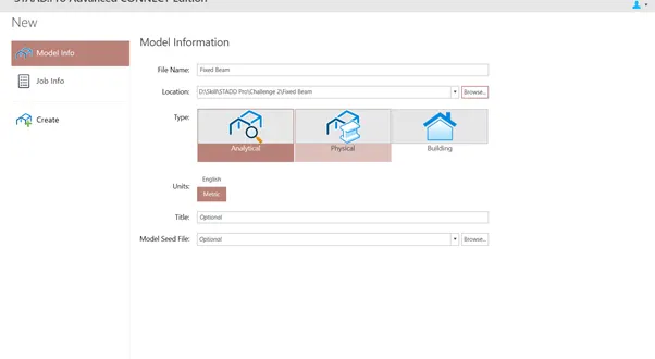
- Open STADD Pro. Click on New model.
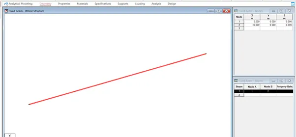
- Then use Grids, Beam Grids and give start point as 0,0 and End as 16m,0
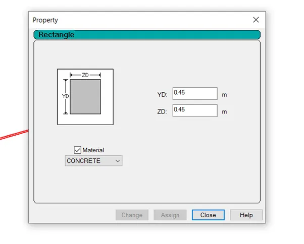
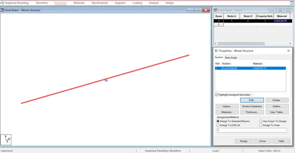
- Then properties create new.
- Rectangular beam of 450 x 450 then give material as Concrete.
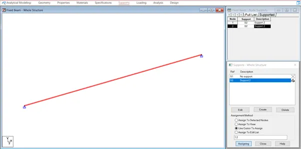
- Go to Support and then create Fixed Support.
- Then Assign supports to both ends respectively.
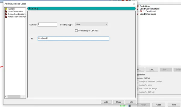
- Then give load. Create load case give live and add.
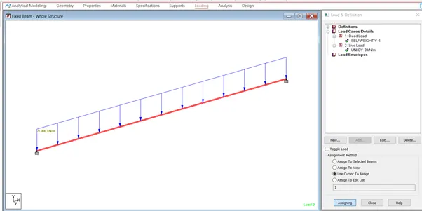
- Then edit load case give uniformly distributed load of 9KN/m.
- Then use courser to assign and click on created nodes.
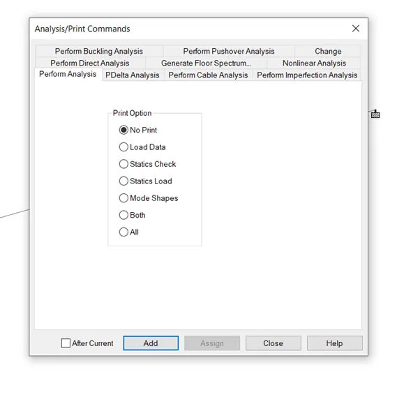
- Then go to analysis and perform analysis and then run.
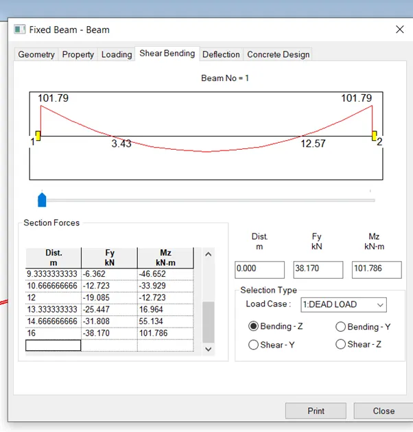
- Then take the output and shear force and bending moment diagram.
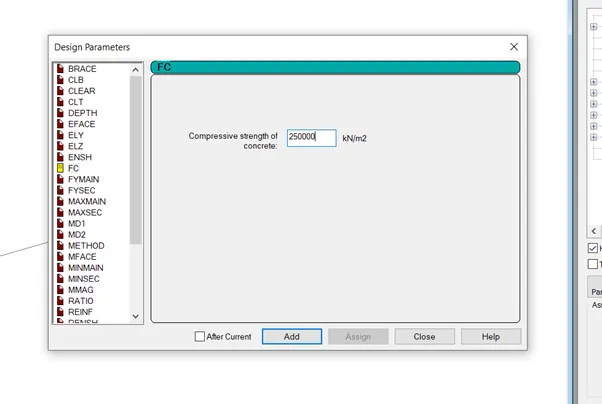
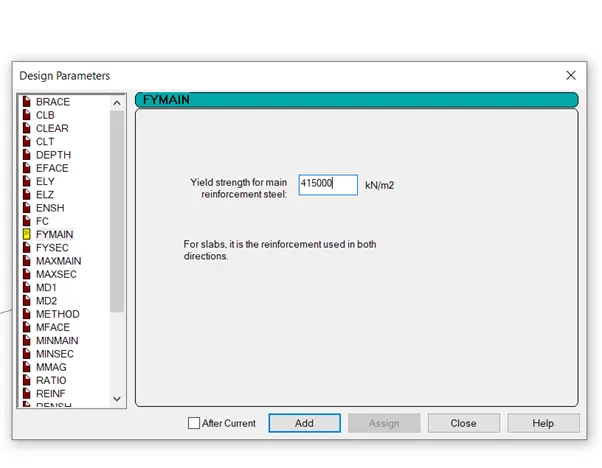
- Then go to design and provide design Parameters as Fck 25N/mm2 and Fy as 415 N/mm2
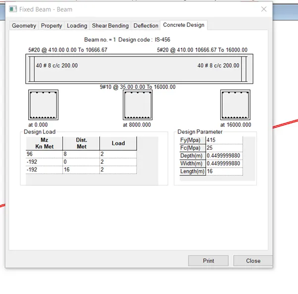
- Then run the Analysis and right click on the beam to get the result.
Input

Output & Result
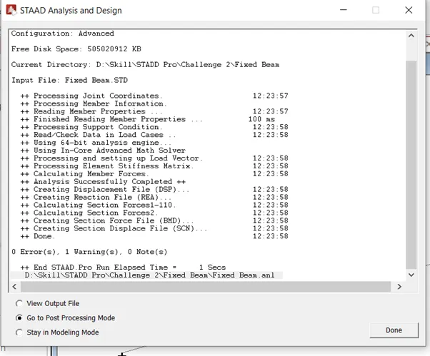
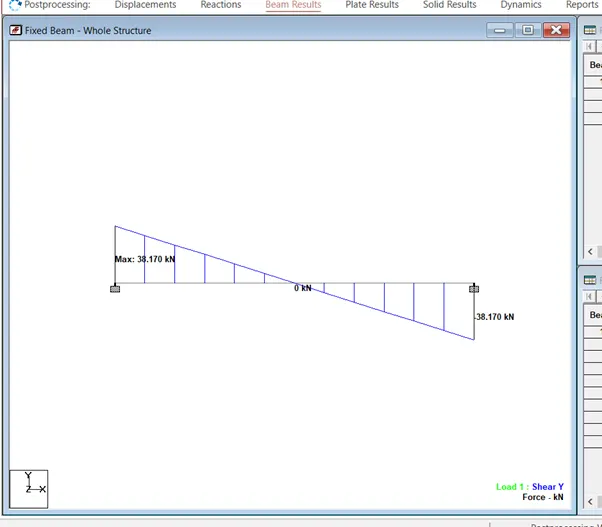
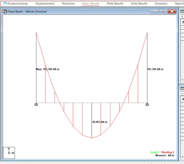

Thus the Analysis and Design of Beam is Done.