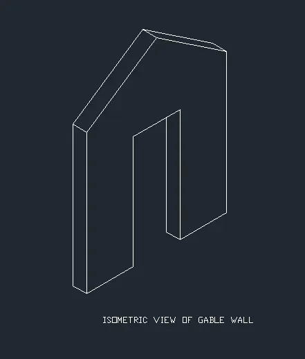
Creating a Floor plan, Footing detail and Isometric view using AutoCad
Aim
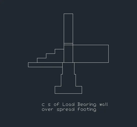
To draw CS of Load Bearing Wall Over Spread Footing by using Auto Cad in Direct Distance entry Method.
Procedure
CS of Load Bearing Wall Over Spread Footing
Specify line commend and enter the first point as 1,1. A point will be created on the spread sheet. Keep the courser left side and then enter 0.90 units then in upwards and enter 0.25 units.
Keep the courser in right side and enter 0.20 units. Then keep the courser in upward direction and enter 0.40 units. Then in left and 0.05 units.
Keep the courser in upward then enter 0.40.in left side enter 0.05 and in upward enter 1.65 units. A line of 1.65 units in upward direction is created.
Keep the courser left side and enter 0.30. then in down ward enter 1.2 unit. keep the mouse courser in left side and enter 0.30 units and in down ward 0.15 units.
Keep the courser in left side and enter 0.30 units and in down wards and enter 0.15 units. Then in left side at 0.30units and down word as 0.15 units.
Then in left side as 0.30 units and in down wards as 0.15 units and in rights side 1.15 units. And press enter.
Specify the line commend and enter the first point at 1.05 unit in y axis and specify second point as 1.15 units right side. Keep the courser upward and enter 0.60 unit. Move the courser left side and enter 1.5 units.
Keep the courser up and enter 0.05 and then in left and enter 0.30 then close.
The required drawing for CS of Load Bearing Wall Over Spread Footing is Created.
Output
Aim
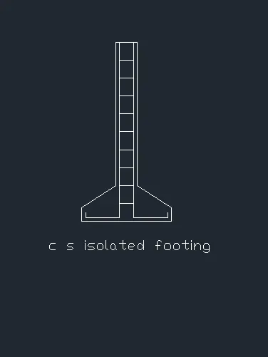
To draw CS of Isolated Footing by using Auto Cad in Direct Distance entry Method.
Procedure
CS of Isolated Footing
Specify line commend and enter the first point as 1,1. Then enter next point as 1unit in left side. Keep the courser up and enter 0.15 units.
Then keep the courser up and @45,0.38. then keep the courser up and enter 1.60 units
Keep the courser left side and enter 0.24 units.
Specify mirror commend and select the entire object and specify the mid-point in the 1 unit line and press enter.
From the top of the drawing specify first point and enter 0.04 left side and keep the courser down ward and enter 0.20 units and keep courser right side and enter 0.16 units and close.
Specify the line commend and enter the first point and extend the line 0.04 units above the base line. specify offset commend and enter 0.16 select offset line and drag the mouse right side and click enter.
Specify offset commend and enter 0.20 units and select the line to which offset ids to be done. Drag the mouse down and enter. Repeat the procedure till required and press enter.
Specify line commend and enter 0.38 at the left side. Press enter to escape from the commend. Specify line commend and enter 0.38 in the right side of first point.
Thus the CS of Isolated Footing is created.
Output
Aim
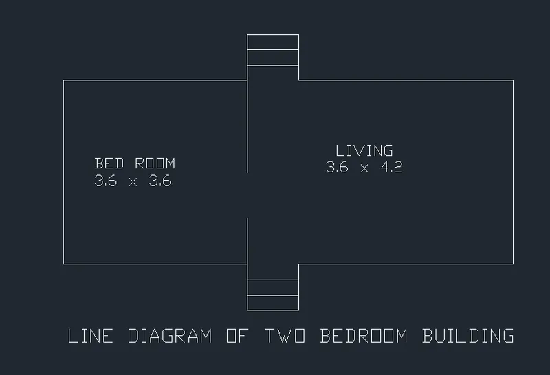
To draw the Line Diagram of Two Bedrooom Building by using Auto Cad in Direct Distance entry Method.
Procedure
Line Diagram of Two Bed Room Building
Specify the line commend and enter the first point as 1,1. Enter the next point as 3.60 units in up ward direction.
Keep the courser left side and enter 3.60 units in left direction. Move the mouse courser up and enter 0.30,0.30 and 0.30 units in up ward direction. Then keep the mouse right and enter 1 unit.
Drag the mouse downward direction and enter 0.30,0.30and 0.30. then keep the mouse left and enter 4.20 units. Keep the mouse downward and enter 3.60 units
Keep the mouse right and enter 4.20 units and keep the mouse down and enter 0.30,0.30and 0.30. move the cursor left and enter 1 unit’
Move the courser up and enter 0.30,0.30 and 0.30 in upward direction. Then enter close to complete the drawing.
Specify the Line commend and enter the first point at 3.60 units left side in bed room and in upward enter 0.90 units.
Specify the line commend and enter the first point at top left side of the bed room and in down ward enter 1.80 units.
Specify offset commend and enter 0.30 units and press enter and specify the 1-unit line and enter two times in upward steps and also in down ward steps.
Thus, the line drawing of a two-bedroom building is created.
Output
Aim
To draw CS of Load Bearing Wall Showing Foundation by using Auto Cad in Direct Distance entry Method.
Procedure
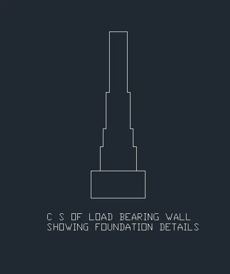
CS of Load Bearing Wall Showing Foundation Details
Specify Rectangle commend and enter the dimension. Specify the length of rectangle as 0.90 units and width of rectangle as 0.45 units. Specify the point to place the rectangle.
Specify line commend and specify the first point at top left of rectangle and enter 0.15 units in right.
Keep the courser upward and enter 0.40 units and then in right and enter 0.05 units. Keep the courser up and enter 0.30 units. Then enter 0.05 in right and enter 0.60 in upward.
Keep the courser right side and enter 0.40 units. keep the courser down ward and enter 0.60 units.
Keep the courser left and enter 0.05 units and move courser down and enter 0.30 units then move the courser left and enter 0.05 units and move downward and enter 0.40 units and enter escape.
Specify the line commend and enter the first point at the top left and keep the courser right and enter 0.05 and move the courser up and enter 1 unit.
Keep the courser right and enter 0.30 units and move down ward and enter 1 unit and press escape.
Output
Aim
To draw Isometric view of Steps by using Auto Cad in Direct Distance entry Method.
Procedure
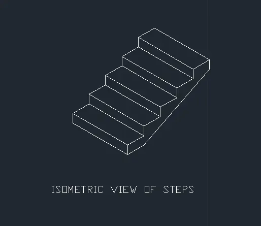
Isometric View Of Steps
Specify the isometric drafting on and specify the line commend and keep the isometric in left and enter 1 unit keep the courser up and enter 0.15. keep the courser left and enter 1 unit. Move the courser down and enter 0.15 unit.
Specify line commend and change isometric drafting to right and enter 0.30. then move the courser to left and enter 1 unit. Then close the line.
Select the z axis lines and enter copy commend specify the base point and paste it in the corner of x axis line.
Select the x axis lines and enter copy commend and specify base point at any corner and paste it in the same corner of the z axis line.
Repeat the same procedure for about 4 steps and then keep the isoplane right and move the courser down ward and enter 0.15 and join first and last step inclined.
Thus the isometric view of step is created
Output
Aim
To draw Isometric view of Gable wall by using Auto Cad in Direct Distance entry Method.
Procedure
Isometric View of Gable Wall
Specify isometric drafting on and press f5 to change isoplane left and specify line commend, keep the courser down and enter 0.30 units and move courser up and enter 3 units.
Move courser to left and enter 0.30 units and in down and enter 3 units.
Specify line commend and specify star point and enter 1 unit in right direction. In upward direction change isoplane to top and enter 2.42 units. Move courser to right and renter 1 unit and in downward enter 2.42 units.
Keep the courser in right and enter 1 unit and in upward enter 3 units. Mark center point and join both the sides.
Thus the isometric view of gable wall is created
Output