Drafting of various geometries using Chamfer, Fillet tool in AutoCad
1
AIM
To draw the given drawing by using Auto Cad in Direct Distance entry Method.
PROCEDURE
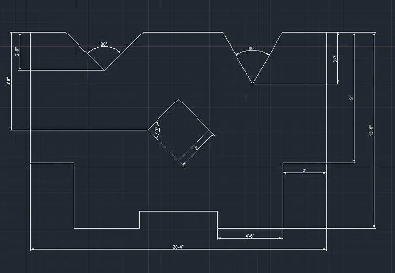
Open AutoCAD and enter quick settings then give decimal and set limits of page.
Specify line commend and enter 0,0 as first point, then mention second point as 3 in positive X axis. Next point mention < 135 at distance of 2.12 units
Specify next point as <90 at 2.38 units. Then in negative X axis give 2 units. Then enter close.
From 0,0 move 1.5 units in Positive X axis and in Positive Y axis move 1 unit then create a circle of 1.2 diameter.
With same center move 2.5 units in Positive Y Axis and create a circle of 0.80 diameter.
Thus the drawing is created
OUT PUT
2
AIM
To draw the given drawing by using Auto Cad in Direct Distance entry Method.
PROCEDURE
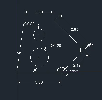
Open AutoCAD and enter quick settings then give Architectural and set limits of page.
Specify line commend and enter first point as 0,0. Then enter 8 feet in Positive X axis then in negative Y axis enter 1’9” then <135 at a distance of 2’10”.
At start point in Negative Y axis enter 2’5” and then < 40 at a distance of 3’ at < 90 enter 2’6” ant join the two lines.
Thus the drawing is created.
OUT PUT
3
AIM
To draw the given drawing by using Auto Cad in Direct Distance entry Method.
PROCEDURE
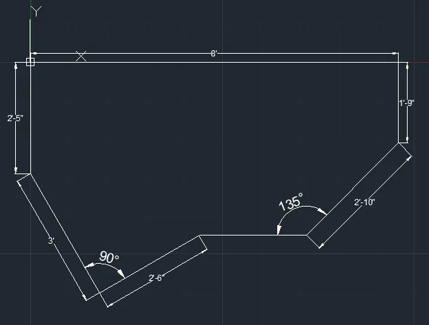
Open AutoCAD and enter quick settings then give Engineering and set limits of page.
Specify line commend and enter 0,0 then in Positive X axis enter 5’0.1” and in positive y axis enter 1’6”.
At 0,0 in Positive y axis enter 3’3” and in Positive X axis enter 2’6.5” then join the line.
From 0,0 move 1’3” in positive X axis and in positive Y axis move 1’6” then create a circle of 1’6”diameter.
Mark all the dimensions, thus the drawing is created.
OUT PUT
4
AIM
To draw the given drawing by using Auto Cad in Direct Distance entry Method.
PROCEDURE
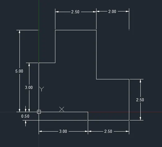
Specify line commend and enter 0,0 as first point and specify next point as 3.5 units in Positive y axis, then enter 1 unit in positive X axis. Then in Positive Y axis enter 2 units.
Then specify next point as 2.50 in Positive X axis then in Negative Y axis enter 3.5 units.
Then enter 2 units in Positive X axis then in negative Y axis enter 2.50 units.
Then in negative X axis enter 2.50 units then in positive Y axis enter 0.5, then in Negative X axis enter 3 units.
Enter all the dimensions, thus the drawing is created.
OUT PUT
5
AIM
To draw the given drawing by using Auto Cad in Direct Distance entry Method.
PROCEDURE
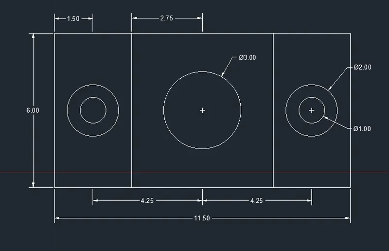
Specify the rectangle commend and enter dimensions in that commend. Specify the length of rectangle as 11.50 units and breadth of rectangle as 6 units, and press enter.
Specify line commend and enter first point at the start of rectangle and in positive X direction move 3 units and in positive Y axis enter 6 units and close.
From there in Positive X axis enter 5.50 units and in negative Y axis enter 6 units.
Specify midpoint of each rectangle and create a circle of 1 unit diameter and 2-unit diameter from same center.
The same will be copied to the last rectangle.
In center create a circle of unit’s diameter
Thus the drawing is created.
OUT PUT
6
AIM
To draw the given drawing by using Auto Cad in Direct Distance entry Method.
PROCEDURE
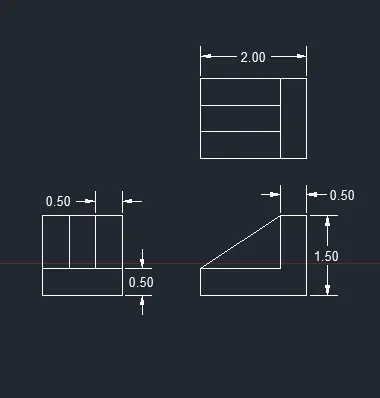
Specify the line commend and enter 0,0 as first point and enter 2 units in positive X axis, then in Positive Y axis enter 1.5 units
Then in negative X axis enter 0.5 units and in negative Y axis 1 units and in Negative X axis 1.5 units and then enter close.
Then draw the elevation and section of the same.
Thus the drawing is created.
OUT PUT
 .
.
7
AIM
To draw the given drawing by using Auto Cad in Direct Distance entry Method.
PROCEDURE
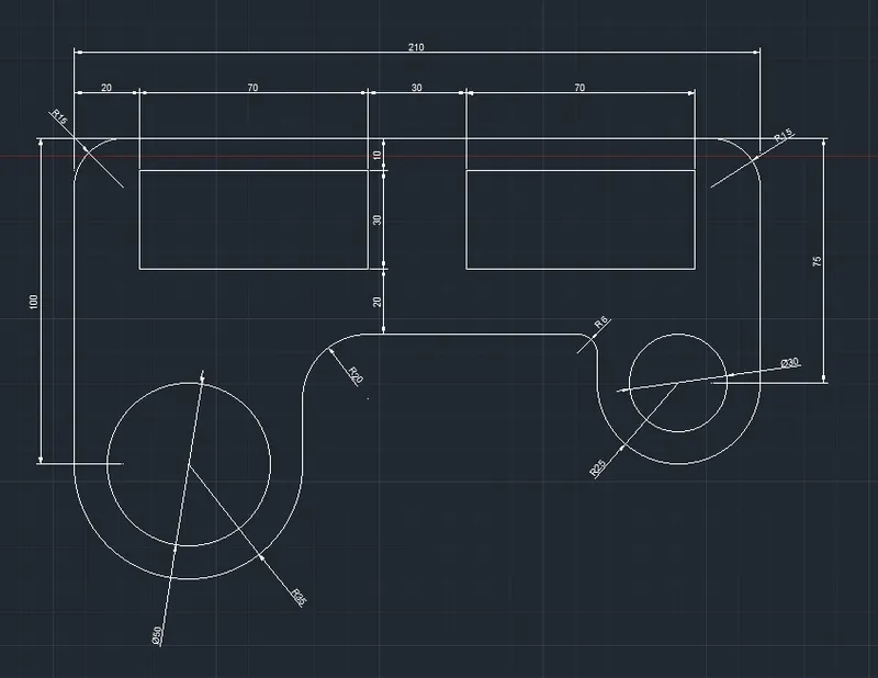
Specify line commend and enter 210 units in Positive X axis and enter 75 units in Negative Y axis then at the start poin in Negative Y axis enter 100 units.
Then use arc commend and enter the radius as 35 and click on the line a arc of 35 units will be created
Then at the right side create an arc of radius of 25 units the click on the right side line a arc will be created.
Then join both the lines of arc and enter.
Then use fillet commend and enter radius of 15 and click at the top right and left corner.
Then use fillet in left side with radius of 20 units and in right side radius of 6 units.
Create a rectangle of dimensions 70 units length and 30 units breadth and place it 20 units in positive X axis and 10 units in Negative Y axis. Then copy the same rectangle and place parallel to the previous one at a distance of 30 units away in positive X axis.
In bottom left create a circle of 50 units diameter and in right center create a circle of 30 units diameter.
Thus the drawing will be created.
OUT PUT
8
AIM
To draw the given drawing by using Auto Cad in Direct Distance entry Method.
PROCEDURE
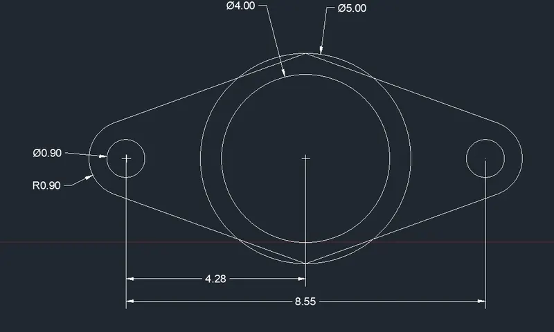
Specify circle commend and enter diameter as 4 units and 5 units with same center.
At a distance of 4.275 units from the Centre of circle to the center of another small circle of diameter 0.90 units on both sides.
Specify the line commend and join the center circumference of the circle on both sides.
Use fillet commend and enter radius of 0.90 units on both sides of the circle.
Thus the drawing is created.
OUT PUT
9
AIM
To draw the given drawing by using Auto Cad in Direct Distance entry Method.
PROCEDURE
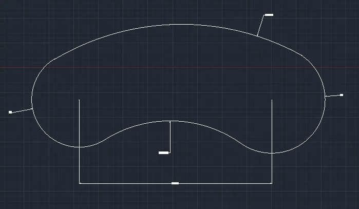
Specify line commend press I the screen for first point and enter 32’6” for next point.
Use arc commend and enter the radius of 8 units at the left end and from the right end use 9 units as radius.
Use fillet commend and enter radius of 20’10” and select first point as the bottom right-side arc and second point as bottom left arc.
Repeat the commend and enter radius of 41’8” and select first point as the top right-side arc and second point as top left side arc.
Thus the drawing is created.
OUT PUT
10
AIM
To draw the given drawing by using Auto Cad in Direct Distance entry Method.
PROCEDURE
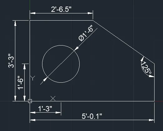
Specify line commend and enter 0,0 then enter next point as 6’9” in Negative Y axis then in positive X axis 3’ and in negative Y axis 4’6”.
Then in Positive X axis enter 4’6” in positive Y axis 1’2” and in positive X axis 5’4”.
In negative Y axis enter 1’2” and in positive X axis enter 4’6” then in Positive Y axis enter 4’6” then in positive X axis 3’.
In Positive Y axis enter 9’ and in Negative X axis enter 10’2”and the in Negative Y axis enter 10’2”.
Select the midpoint of first 10’2” and in Negative Y axis enter 3’7” and in Positive X axis enter <30 and join, Repeat this for opposite side as well.
Select the midpoint of second 10’2” and in Negative Y axis enter 2’8” and in Positive X axis enter <45 and join, Repeat this for opposite side as well.
Create a square of 3’ and place it at the center of drawing.
Thus the drawing is created.
OUT PUT