Week 2 Challenge
I
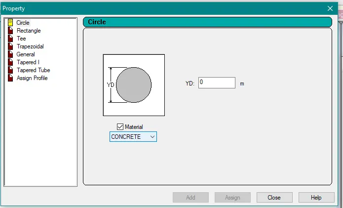
1. How will you assign Circular section to column?
Go to properties> Define parameters
Assign the circular shape of the column
Provide a radius to the circular section
2. How will you assign Unit system to a .STD model file?
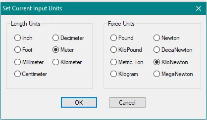
Go to Tools> Set Current Input Units
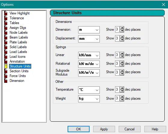
Go to Tools> Set Current Display Units
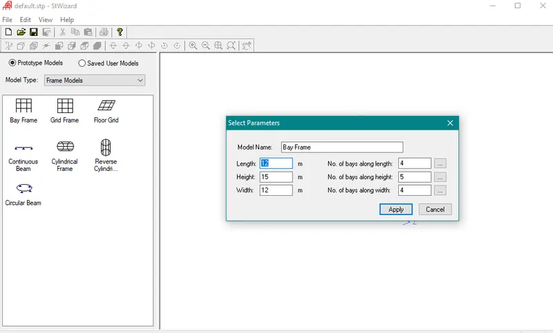
3. What are the parameters to be specified while using “Bay Frame” option?
Open the Structural wizard
Select Frame model> Bay frame
Enter the required parameters:
Length
Height
Width
No. of bays along length
No. of bays along height
No. of bays along width
4. Name few codal standards incorporated in STAAD Pro software.
STAAD Pro software contains design codes for a variety of materials viz. Steel, Concrete, Timber, and Aluminium. The program contains various codes that are being used in a particular region.
The design codes incorporated in STAAD Pro for designing in Indian region are as follows:
Indian Codes - Concrete Design per IS 456
Concrete Design per IS 13920
Steel Design per IS 800 – 1984
Steel Design per IS 800 – 2007
Steel Design per IS 802 – 1995
Design per Indian Cold Formed Steel Code 801 – 1975
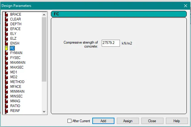
5. How will you specify the design compressive strength for a RCC section?
Go to the design tab> Concrete
Select the respective code (IS456:2000)
Select Define parameter> FC
II
1. State the “Input” steps involved in RCC design.
Following are the required steps for RCC design in STAAD Pro
- Create geometry
- Assign property
- Assign material
- Assign supports
- Assign loads
- Analyse the model
- Select on design tab
- Select IS code
- Run the analysis
2. Explain the difference between Fixed and Enforced support condition in STAAD Pro.
When the fixed or fixed but type of support is specified, for those degrees of freedom which are to be treated as fully restrained, STAAD assumes the displacements to be known quantities whose value is zero. Hence, those degrees of freedom are not considered for the stiffness matrix, and their value is not calculated. (For the FIXED BUT support type, if any degrees of freedom are assigned a spring using the KFX thru KMZ terms, those are treated as unknowns and their displacements are calculated).
When the enforced or enforced but type of support is specified, for those degrees of freedom which are to be treated as restrained, STAAD assigns a spring with a very high spring stiffness - translational stiff springs for translational restraints, and rotational stiff springs for rotational restraints. Those degrees of freedom which are free to displace are assigned springs of zero stiffness. Hence, for all the 6 degrees of freedom at such supports, the displacements are calculated. The ones which have a stiff spring will end up having a negligible displacement, and those with zero-stiffness-springs will have a displacement based on the structure geometry, properties and loading.
The number of unknowns is less in the fixed support condition compared to the enforced support condition, hence the time required to compute the results will also be comparatively less in the first method. If the model is large, there may be a significant reduction in time required to perform the analysis.
III
1. Explain the steps involved in analysis of a model using STAAD Pro sequentially.
The following steps to be considered for the analysis and designing of RCC building by using STAAD Pro software
i. Modelling of building
It includes assigning Material, Loads, Support Condition, Specification, and Property of the structural elements
ii. Applying the load cases
After creating the building model and assigning the supports conditions the next step is to create load cases apply them for building. The loads related to the dead load, live loads are initially defined through the load cases and details option. Under the dead load the loads related to the self-weight with factor 1, wall loads (external wall load, internal wall load and parapet wall load) floor loads are defined and under the live load case the slab floor load is added.
iii. Analysis of building
Once the input file is completed, choose the type of analysis need to be performed on the structure. The STAAD analysis engine performs analysis and design sequentially with a single click. In order to carry out the design, the design parameters must be specified along with geometry, properties, etc. in the input file. Also, the design code used for design and code check can be changed before performing the analysis and design.
The Analytical Modelling and Physical Modelling of the STAAD Pro user interface are used to prepare the structural input data which is then passed to the STAAD analysis engine for general purpose structural analysis and design.
2. Explain the two ways in which a structural framework/model can be created in STAAD Pro software.
Node by Node
One way to model a building is by adopting the node by node method. In this method, all the nodes of the structure as per the Architectural layout are placed manually by specifying the coordinates. The same nodes are then translationally repeated based on the building dimensions and levels.
Structure Wizard
This is a more automated technique as compared to the node by node method. You can model certain type of structure like truss, frame, and many more by adopting this method. There are further various methods within structure wizard using which the building can be modelled.
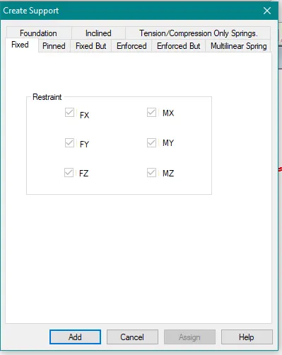
3. Elaborate the different support conditions in STAAD Pro.
STAAD Pro provides facilities to assign support both parallel and inclined orientation to global axes. The supports that can be specified are:
Fixed: Resist all type of movement in all directions i.e. a fixed support have reactions for all forces and also for all moments.
Pinned: Resist translational movement but provides no resistance against rotation.
Fixed but: Facilitates release supports in all desired directions but against forces and moments i.e. Fx, Fy, Fz, Mx, My, Mz and others.
Enforced: Assigns a spring with a very high spring stiffness - translational stiff springs for translational restraints, and rotational stiff springs for rotational restraints.
Enforced but: Those degrees of freedom which are free to displace are assigned springs of zero stiffness.
Multilinear spring: When soil is modelled as spring supports, the varying resistance it offers to external loads can be modelled using this facility, such as when its behaviour in tension differs from its behaviour in compression.
Foundation: Represents the soil structure interaction of practical field in support. We can provide isolated footing, mat footing inputs with linear and multi-linear springs. One can also provide plate mat or elastic mat option depending on the structure. But it requires some more input like subgrade modulus of elasticity.
Inclined: Refers to the fact that the restraints at a joint where such a support is specified are along a user-specified axis system instead of along the default directions of the global axis system
Tension/compression only springs: Tension-only springs are capable of carrying tensile forces only. Thus, they are automatically inactivated for load cases that create compression in them. Compression-only springs are capable of carrying compressive forces only. Thus, they are automatically inactivated for load cases that create tension in them.
4. How will you extract the stress distribution for a staircase slab?
After running the analysis successfully, go to the post-processing mode.
Right click> Structure diagrams.
Choose Plate stress Contour Tab
STAAD pro will showcase the stress distribution divided into different colour zones ranging from minimum to maximum stress values.
5. Explain the different ways to view SFD & BMD in STAAD Pro.
Go to post-processing mode after running the analysis successfully.
Click on the beam tab.
A tool palette at top shows various values such as shear force and bending moments.
To draw the diagram, click on Fy for the shear force diagram.
Click on the Mz for obtaining the bending moment diagram.
IV Practical
1. Analyse the following structural elements and validate the results
A. Simply Supported Beam
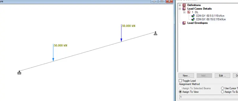
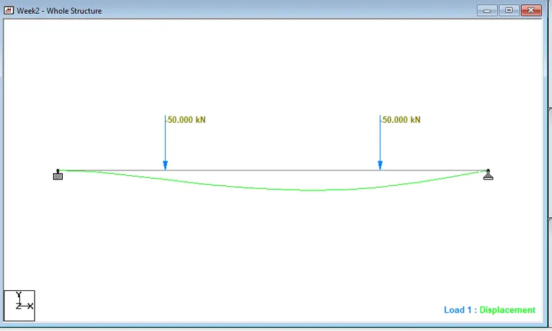
a. A Simply supported beam with two point loads symmetrically placed
b. Span L = 20m
c. Load P = 50kN each
d. Both P located at 5m from each support
PROCEDURE
Open STAAD> Create a New Model
After clicking on the new model provide the project details.
Click on create to start a new project.
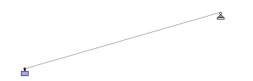
Go to geometry and create the first node at X-0, Y-0, and Z-0.
Then, select the node with the node cursor.
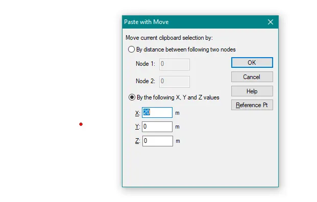
Copy and paste the node at 20 meters in the X-direction
Go to add beam> select first node then second to create a beam of the proposed length.
Nodes
Beam
Go to Support> Add> Fixed> Select One Node> Assign To Selected Nodes.
Similarly, create another Support> Pinned
Select The Other Node>Assign to selected.
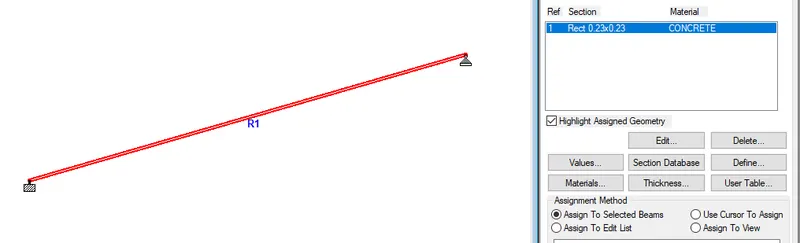
Go to Properties>Define>Concrete Rectangular>Specify Dimensions
Now select the beam and assign the section property.
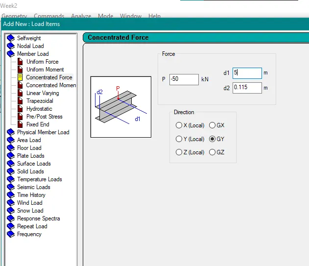
Go to Loads> Create> Member Load> Concentrated Force> Global Y= -50KN, D1=5, D2=0.115.
Now, select the load and beam and check the radio button to assign the load.
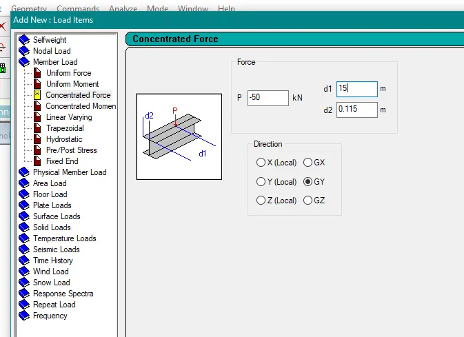
Go to Loads> Create> Member Load> Global Y= -50KN, D1=15, D2=0.115.
Now, select the load and beam and check the radio button to assign the load.
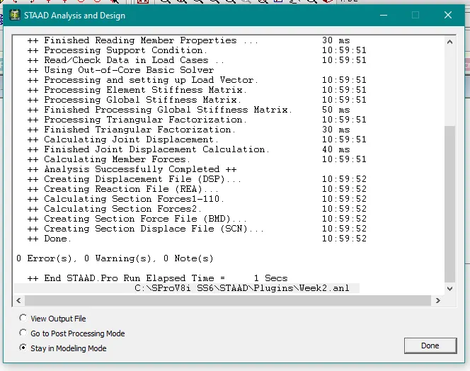
Select the analysis method that is performed analysis from the design and analysis panel.
Run analysis.
RESULTS
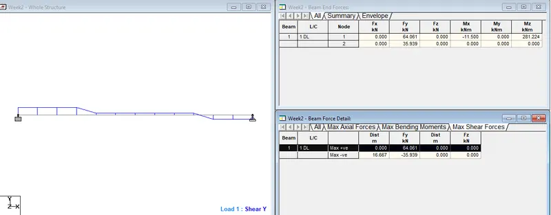
Go to the Post-Processing Mode>Select the Load Cases>Hit Apply>ok.
Then, all the analysis results will be automatically visible on your STAAD screen.
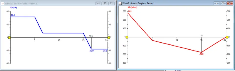
Select beam results> Mz for bending moment> Fy for shear force diagram.
Shear Force Diagram
Bending Moment Diagram
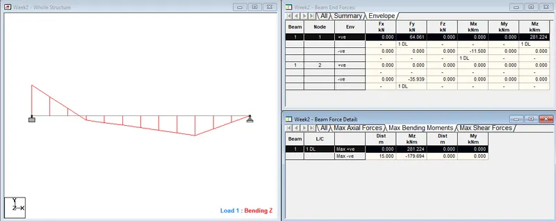
SFD and BMD
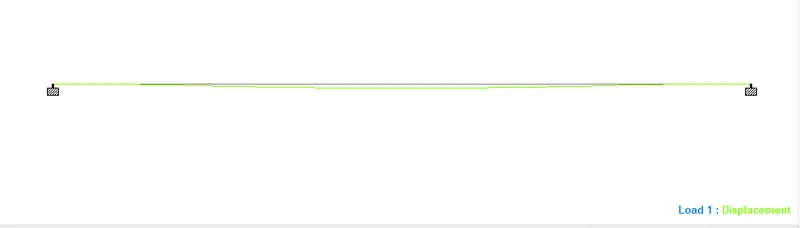
Displacement
B. Fixed Beam
a. Span L = 16m
b. Uniformly Distributed Load w=9kN/m
PROCEDURE
Open STAAD> Create a New Model
After clicking on the new model provide the project details.
Click on create to start a new project.
Go to geometry and create the first node at X-0, Y-0, and Z-0.
Then, select the node with the node cursor.
Copy and paste the node at 16 meters in the X-direction
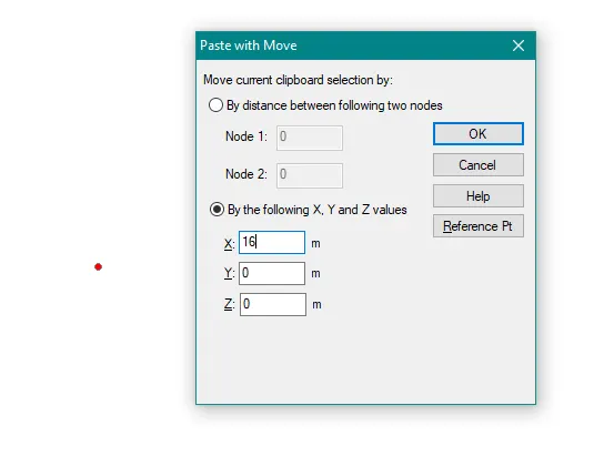
Go to add beam> select first node then second to create a beam of the proposed length.
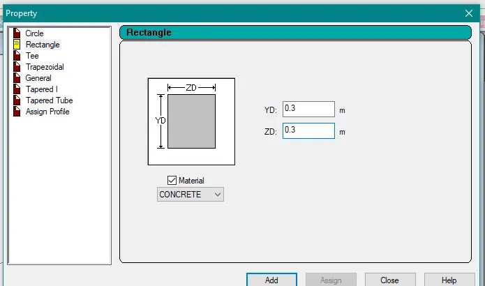
Go to Properties>Define>Concrete Rectangular>Specify Dimensions
Now select the beam and assign the section property.
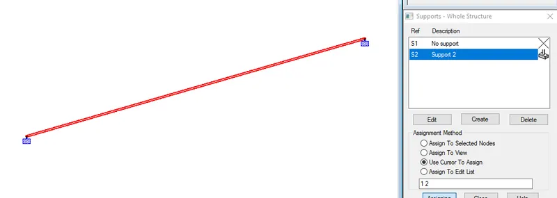
Go to Support> Add> Fixed> Select One Node> Assign To Selected Nodes.
Similarly, create another Support> Fixed But> Release Moments and Horizontal Restraints>
Select The Other Node>Assign to selected.
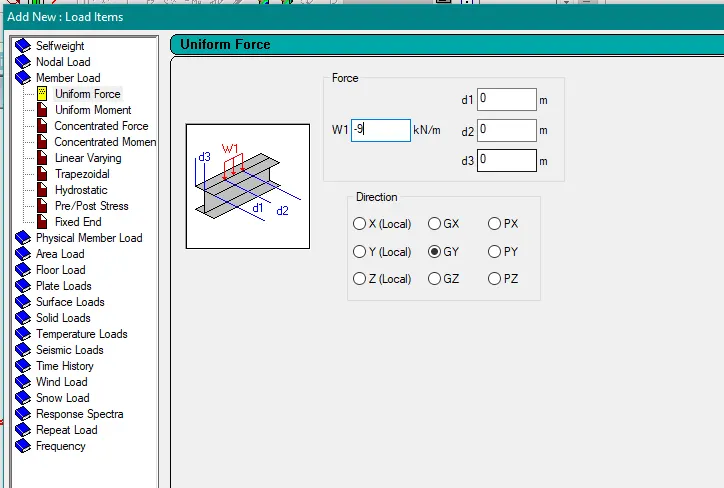
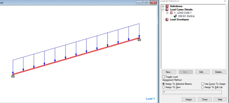
Go to Loads> Create> Member Load> Uniform Force> Global Y> W1=-9kN/m
Now, select the load and beam and check the radio button to assign the load.
Select the analysis method that is performed analysis from the design and analysis panel.
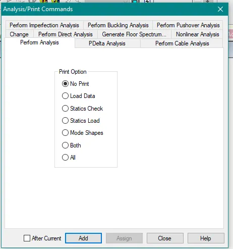
Run analysis.
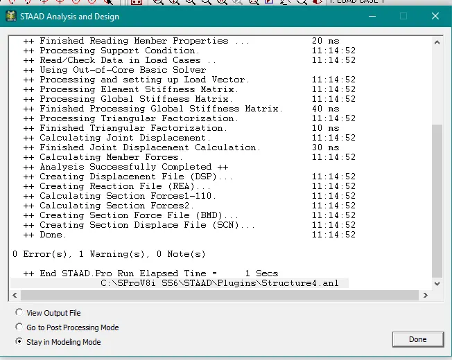
RESULTS
Draw SFD and BMD
Go to the Post-Processing Mode>Select the Load Cases>Hit Apply>ok.
Then, all the analysis results will be automatically visible on your STAAD screen.
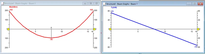
Select beam results> Mz for bending moment> Fy for shear force diagram.
Shear Force Diagram
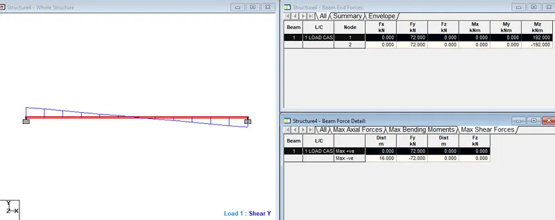
Bending Moment Diagram

BMD and SFD
Displacement