Drafting of various geometries using Chamfer, Fillet tool in AutoCad
AIM
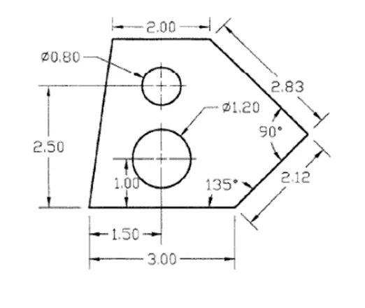
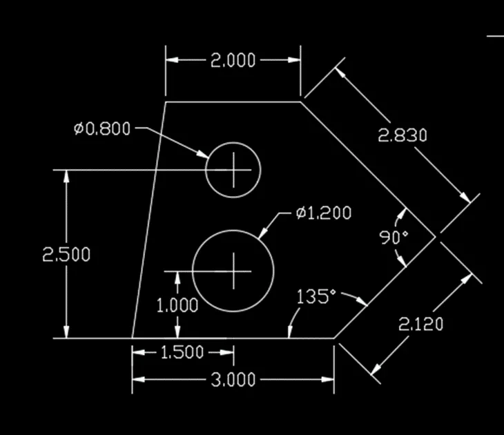
To create the following geometry in AutoCAD.
PROCEDURE:
Enter LINE command: L
LINE specify first point: 1,1 (X=1, Y=1)
Specify next point or [Undo]: 3,0
Specify next point or [Undo]: @2.12<135
Specify next point or [Close Undo]: @2.83<90
Specify next point or [Close Undo]: @2<180
Specify next point or [Close Undo]: C
Enter POINT command: PO
POINT specify a point: Click at the bottom left vertex
Enter MOVE command: M
MOVE select object: select the point and move RIGHT by 1.5
Enter MOVE command: M
MOVE select object: select the point and move UP by 1
Enter COPY command: CO
COPY select object: select the point and copy it UP by 1.5
Enter CIRCLE command: C
CIRCLE Specify center point for circle: click on the points
Specify radius of circle or[Diameter]: D
Specify diameter of circle: 0.8
Enter CIRCLE command: C
CIRCLE Specify center point for circle: click on the points
Specify radius of circle or[Diameter]: D
Specify diameter of circle: 1.2
RESULT
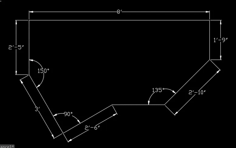
AIM
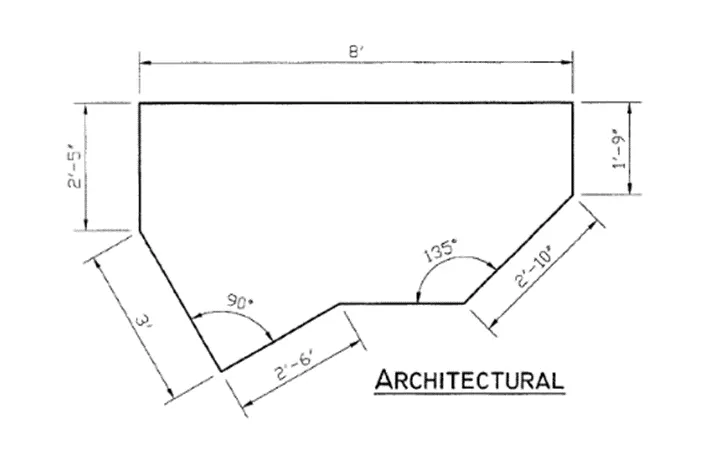
To create the following geometry in AutoCAD.
PROCEDURE:
Enter LINE command: L
LINE specify first point: click left mouse button, drag the mouse right and type 8’
Specify next point or [Undo]: drag the mouse down and type 1’9”
Specify next point or [Undo]: @2’10”<225
Specify next point or [Close Undo]: @2’4”<180
Specify next point or [Close Undo]: @2’6”<210
Select POLA TRACKING ON with relative angle measurement
Specify next point or [Close Undo]: @3’<90
Specify next point or [Close Undo]: C
RESULT
AIM
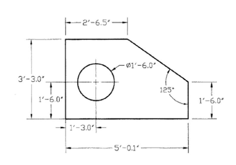
To create the following geometry in AutoCAD.
PROCEDURE:
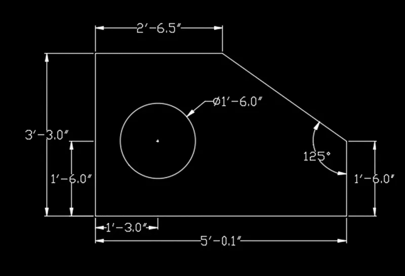
Enter LINE command: L
LINE specify first point: click left mouse button, drag the mouse right and type 5’0.1’
Specify next point or [Undo]: drag the mouse UP and type 1’6”
Enter LINE command: L
LINE specify first point: click the start point of figure
Specify next point or [Undo]: drag the mouse UP and type 3’3”
Specify next point or [Undo]: drag the mouse RIGHT and type 2’6.5”
Specify next point or [Undo]: join the two vertices
Enter POINT command: PO
POINT specify a point: Click at the bottom left vertex
Enter MOVE command: M
MOVE select object: select the point and move RIGHT by 1’3”
Enter MOVE command: M
MOVE select object: select the point and move UP by 1’6”
Enter CIRCLE command: C
CIRCLE Specify center point for circle: click on the points
Specify radius of circle or[Diameter]: D
Specify diameter of circle: 1’6”
RESULT
AIM
To create the following geometry in AutoCAD.
PROCEDURE:
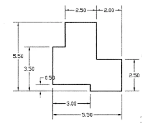
Enter LINE command: L
LINE specify first point: click left mouse button, drag the mouse right and type 3
Specify next point or [Undo]: drag the mouse down and type 0.5
Specify next point or [Undo]: drag the mouse right and type 2.5
Specify next point or [Close Undo]: drag the mouse up and type 2.5
Specify next point or [Close Undo]: drag the mouse left and type 2
Specify next point or [Close Undo]: drag the mouse up and type 3
Specify next point or [Close Undo]: drag the mouse left and type 2.5
Specify next point or [Close Undo]: drag the mouse down and type 2
Specify next point or [Close Undo]: drag the mouse left and type 1
Specify next point or [Close Undo]: drag the mouse down and type 3
Specify next point or [Close Undo]: drag the mouse right and type 3
Specify next point or [Close Undo]: drag the mouse down and type 0.5
Specify next point or [Close Undo]: C
RESULT
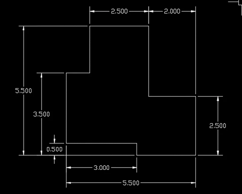
AIM
To create the following geometry in AutoCAD.
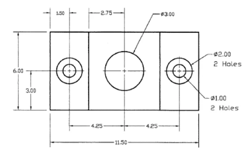
PROCEDURE:
Enter RECTANGLE command: REC [Enter]
RECTANGLE specify first corner point: 10,10
Specify other corner point or [Area Dimension Rotation]: D
Specify length for rectangle<10>: 3
Specify width for rectangle<10>: 6
Specify other corner point or [Area Dimension Rotation]: left click
Enter RECTANGLE command: REC [Enter]
RECTANGLE specify first corner point: click top right corner of the previous rectangle with the mouse
Specify other corner point or [Area Dimension Rotation]: D
Specify length for rectangle<10>: 5.5
Specify width for rectangle<10>: 6
Specify other corner point or [Area Dimension Rotation]: left click
Enter RECTANGLE command: REC [Enter]
RECTANGLE specify first corner point: click top right corner of the previous rectangle with the mouse
Specify other corner point or [Area Dimension Rotation]: D
Specify length for rectangle<10>: 3
Specify width for rectangle<10>: 6
Specify other corner point or [Area Dimension Rotation]: left click
Enter POINT command: PO
POINT specify a point: Click at the geometric center of all three rectangles
Enter CIRCLE command: C
CIRCLE Specify center point for circle: click on the first point
Specify radius of circle or[Diameter]: D
Specify diameter of circle: 1
Enter CIRCLE command: C
CIRCLE Specify center point for circle: click on the same point
Specify radius of circle or[Diameter]: D
Specify diameter of circle: 2
Enter CIRCLE command: C
CIRCLE Specify center point for circle: click on the second point
Specify radius of circle or[Diameter]: D
Specify diameter of circle: 3
Enter CIRCLE command: C
CIRCLE Specify center point for circle: click on the third points
Specify radius of circle or[Diameter]: D
Specify diameter of circle: 1
Enter CIRCLE command: C
CIRCLE Specify center point for circle: click on the same points
Specify radius of circle or[Diameter]: D
Specify diameter of circle: 2
RESULT
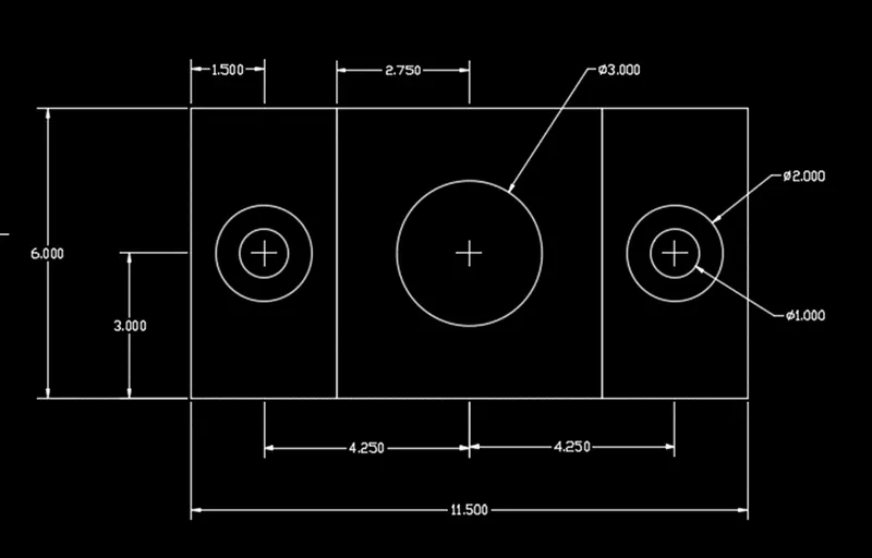
AIM
To create the following geometry in AutoCAD.
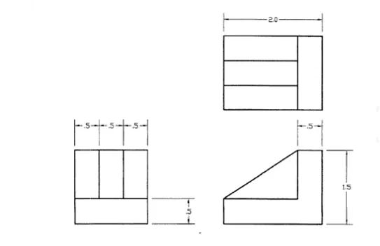
PROCEDURE:
Enter LINE command: L
LINE specify first point: click left mouse button, drag the mouse right and type 2
Specify next point or [Undo]: drag the mouse down and type 1.5
Specify next point or [Undo]: drag the mouse right and type 2
Specify next point or [Close Undo]: C
Enter OFFSET command: O
OFFSET specify offset distance: 0.5
Select object to offset: select the length of the formed rectangle
Specify point on side to offset: repeat thrice
Enter OFFSET command: O
OFFSET specify offset distance: 0.5
Select object to offset: select the breadth of the formed rectangle
Specify point on side to offset: click left side of the breadth
Enter TRIM command: TR
TRIM select object to trim: enter
TRIM: trim the extra length
Enter LINE command: L
LINE specify first point: click left mouse button, drag the mouse right and type 1.5
Specify next point or [Undo]: drag the mouse down and type 1.5
Specify next point or [Undo]: drag the mouse right and type 1.5
Specify next point or [Close Undo]: C
Enter OFFSET command: O
OFFSET specify offset distance: 0.5
Select object to offset: select the breadth of the formed rectangle
Specify point on side to offset: repeat thrice
Enter OFFSET command: O
OFFSET specify offset distance: 0.5
Select object to offset: select the length of the formed rectangle
Specify point on side to offset: click left side of the breadth
Enter TRIM command: TR
TRIM select object to trim: enter
TRIM: trim the extra breadth
Enter LINE command: L
LINE specify first point: click left mouse button, drag the mouse right and type 2
Specify next point or [Undo]: drag the mouse up and type 1.5
Specify next point or [Undo]: drag the mouse left and type 0.5
Specify next point or [Undo]: drag the mouse down and type 1
Specify next point or [Undo]: drag the mouse left and type 1.5
Specify next point or [Close Undo]: C
Enter LINE command: L
LINE specify first point: join the formed figure vertices
RESULT
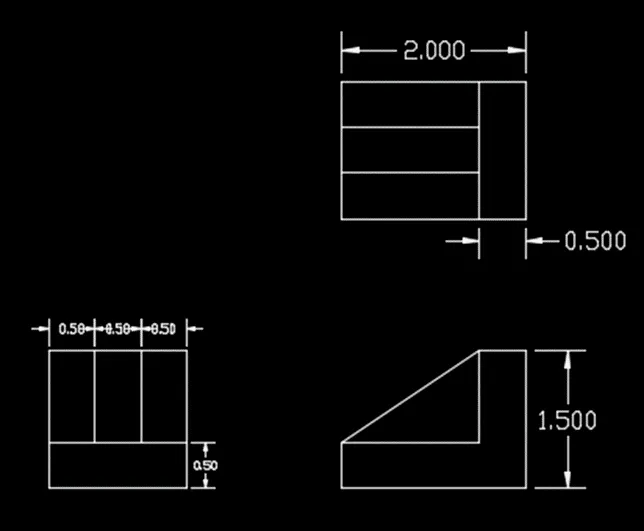
AIM
To create the following geometry in AutoCAD.
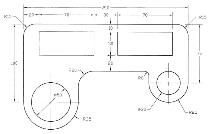
PROCEDURE:
Enter LINE command: L
LINE specify first point: click left mouse button, drag the mouse up and type 100
Specify next point or [Undo]: drag the mouse right and type 210
Specify next point or [Undo]: drag the mouse down and type 75
Enter OFFSET command: O
OFFSET specify offset distance: 50
Select object to offset: select the right vertical line
Specify point on side to offset: click left side
Enter OFFSET command: O
OFFSET specify offset distance: 70
Select object to offset: select the left vertical line
Specify point on side to offset: click right side
Enter OFFSET command: O
OFFSET specify offset distance: 60
Select object to offset: select the horizontal line
Specify point on side to offset: click below it
Enter FILLET command: F
FILLET select first object or [Undo Polyline Radius Trim Multiple]: R
Specify fillet radius: 15
Select first object: select vertical side
Select second object: select horizontal side
Enter FILLET command: F
FILLET select first object or [Undo Polyline Radius Trim Multiple]: R
Specify fillet radius: 15
Select first object: select vertical side
Select second object: select horizontal side
Enter FILLET command: F
FILLET select first object or [Undo Polyline Radius Trim Multiple]: R
Specify fillet radius: 25
Select first object: select vertical side
Select second object: select other verical side
Enter FILLET command: F
FILLET select first object or [Undo Polyline Radius Trim Multiple]: R
Specify fillet radius: 35
Select first object: select vertical side
Select second object: select other verical side
Enter CIRCLE command: C
CIRCLE Specify center point for circle: click on the point
Specify radius of circle or[Diameter]: D
Specify diameter of circle: 50
Enter CIRCLE command: C
CIRCLE Specify center point for circle: click on the point
Specify radius of circle or[Diameter]: D
Specify diameter of circle: 30
RESULT
AIM
To create the following geometry in AutoCAD.
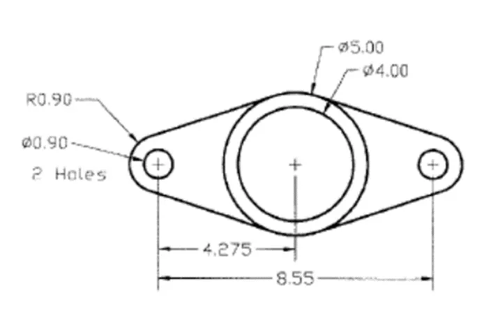
PROCEDURE:
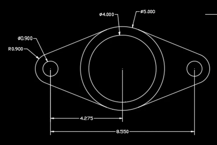
Enter CIRCLE command: C
CIRCLE Specify center point for circle: click on the points
Specify radius of circle or[Diameter]: D
Specify diameter of circle: 1.2
Enter CIRCLE command: C
CIRCLE Specify center point for circle: click on the point
Specify radius of circle or[Diameter]: D
Specify diameter of circle: 4
Enter CIRCLE command: C
CIRCLE Specify center point for circle: click on the same centre point
Specify radius of circle or[Diameter]: D
Specify diameter of circle: 5
Enter POINT command: PO
POINT specify a point: Click at the centre point of the formed circle
Enter COPY command: CO
COPY select object: select the point and copy it left by 4.275
Enter COPY command: CO
COPY select object: select the point and copy it right by 4.275
Enter CIRCLE command: C
CIRCLE Specify center point for circle: click on the points
Specify radius of circle or[Diameter]: D
Specify diameter of circle: 0.9
Enter CIRCLE command: C
CIRCLE Specify center point for circle: click on the points
Specify radius of circle or[Diameter]: 0.9
Enter LINE command: L [Enter]
LINE specify the first point: make tangent from small circle to the bigger circle
Specify next point or [Undo]: click at the tangent
Repeat at all sides
Enter TRIM command: TR
TRIM select object to trim: enter
TRIM: select the lines to be trimmed
RESULT
AIM
To create the following geometry in AutoCAD.
PROCEDURE:
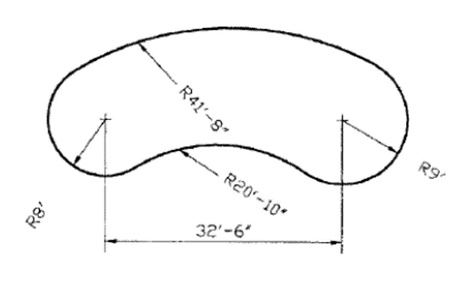
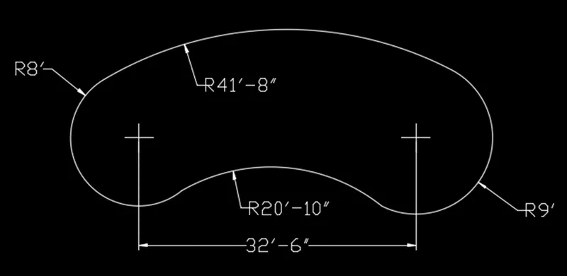
Enter LINE command: L
LINE specify first point: click left mouse button, drag the mouse right and type 32’6
Enter POINT command: PO
POINT specify a point: Click at the two ends of the formed line
Enter CIRCLE command: C
CIRCLE Specify center point for circle: click on the points
Specify radius of circle or[Diameter]: 8’
Enter CIRCLE command: C
CIRCLE Specify center point for circle: click on the same centre point
Specify radius of circle or[Diameter]: 33’8
Enter CIRCLE command: C
CIRCLE Specify center point for circle: click on the point
Specify radius of circle or[Diameter]: 9’
Enter CIRCLE command: C
CIRCLE Specify center point for circle: click on the same centre point
Specify radius of circle or[Diameter]: 32’8
Enter CIRCLE command: C
CIRCLE Specify center point for circle: click on the intersection point of the formed circles
Specify radius of circle or[Diameter]: 41’8
Enter CIRCLE command: C
CIRCLE Specify center point for circle [3P 2P Ttr]: T
Specify point on object for first tangent of circle: click on smaller circle
Specify point on object for second tangent of circle: click on larger circle
Specify radius of circle: 20’10
Enter TRIM command: TR
TRIM select object to trim : enter
TRIM: select the lines to be trimmed
RESULT
AIM
To create the following geometry in AutoCAD.
PROCEDURE:
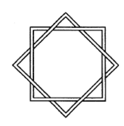
Enter RECTANGLE command: REC [Enter]
RECTANGLE specify first corner point: 10,10
Specify other corner point or [Area Dimension Rotation]: D
Specify length for rectangle<10>: 20
Specify width for rectangle<10>: 20
Specify other corner point or [Area Dimension Rotation]: left click
Enter OFFSET command: O
OFFSET specify offset distance: 1
Select object to offset: select the formed rectangle
Specify point on side to offset: click inside the rectangle
Enter ROTATE command: RO
ROTATE select object: select the rectangles
Specify base point: select the geometric centre
specify rotation angle or [Copy Reference]: C
specify rotation angle or [Copy Reference]: 45
Enter TRIM command: TR
TRIM select object to trim: enter
TRIM: select the lines to be trimmed
RESULT

AIM
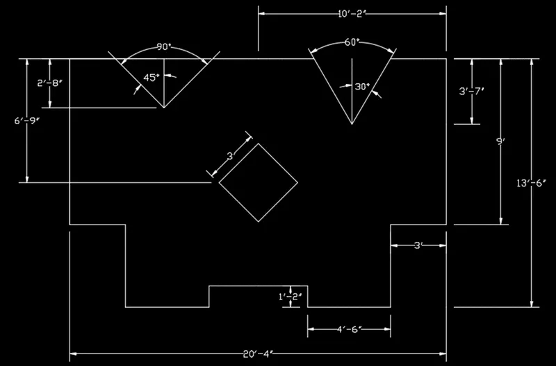
To create the following geometry in AutoCAD.
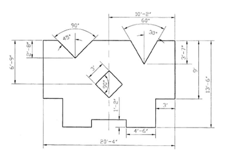
PROCEDURE:
Enter LINE command: L
LINE specify first point: click left mouse button, drag the mouse right and type 10’2
Specify next point or [Undo]: drag the mouse down and type 9’
Specify next point or [Undo]: drag the mouse left and type 3’
Specify next point or [Undo]: drag the mouse down and type 4’6”
Specify next point or [Undo]: drag the mouse left and type 4’6”
Specify next point or [Undo]: drag the mouse up and type 1’2”
Specify next point or [Undo]: drag the mouse left and type 2’8”
Enter MIRROR command: MI
MIRROR select objects: select the created lines
MIRROR select objects: specify first point of mirror line
MIRROR select objects: specify second point of mirror line
Erase sourse object? [Yes No]: N
Enter LINE command: L
LINE specify first point: select mid point of the 10’2” line
Specify next point or [Undo]: drag the mouse down and type 2’8”
Select POLAR TRACKING ON with angle increment of 45
Enter LINE command: L
LINE specify first point: form a 45 degree angle from the bottom of 2’8” line on both sides
Enter LINE command: L
LINE specify first point: select mid point of the 10’2” line
Specify next point or [Undo]: drag the mouse down and type 3’7”
Select POLAR TRACKING ON with angle increment of 30
Enter LINE command: L
LINE specify first point: form a 30 degree angle from the bottom of 3’7” line on both sides
Create a square of side 3’with its geometric centre coinciding with the geometric centre of the formed figure
Enter ROTATE command: RO
ROTATE select object: select the rectangles
Specify base point: select the geometric centre
specify rotation angle or [Copy Reference]: C
specify rotation angle or [Copy Reference]: 45
RESULT