Creating a Floor plan, Footing detail and Isometric view using AutoCad
AIM
To create the following footing detail using AutoCAD
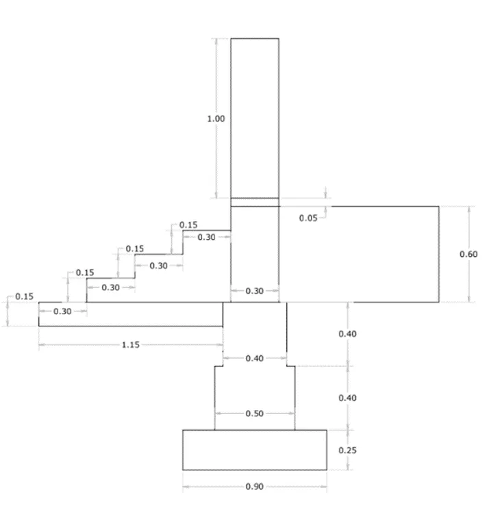
PROCEDURE:
Enter RECTANGLE command: REC [Enter]
RECTANGLE specify first corner point: 10,10
Specify other corner point or [Area Dimension Rotation]: D
Specify length for rectangle<10>: 0.3
Specify width for rectangle<10>: 1
Specify other corner point or [Area Dimension Rotation]: left click
Enter RECTANGLE command: REC [Enter]
RECTANGLE specify first corner point: click bottom left corner of the previous rectangle with the mouse
Specify other corner point or [Area Dimension Rotation]: D
Specify length for rectangle<10>: 0.3
Specify width for rectangle<10>: 0.05
Specify other corner point or [Area Dimension Rotation]: left click
Enter RECTANGLE command: REC [Enter]
RECTANGLE specify first corner point: click the bottom left corner of the previous rectangle with the mouse
Specify other corner point or [Area Dimension Rotation]: D
Specify length for rectangle<10>: 0.3
Specify width for rectangle<10>: 0.6
Specify other corner point or [Area Dimension Rotation]: left click
Enter RECTANGLE command: REC [Enter]
RECTANGLE specify first corner point: click the top right corner of the previous rectangle with the mouse
Specify other corner point or [Area Dimension Rotation]: D
Specify length for rectangle<10>: 1
Specify width for rectangle<10>: 0.6
Specify other corner point or [Area Dimension Rotation]: left click
Enter LINE command: L [Enter]
LINE specify the first point: click the bottom left corner of the previous rectangle with mouse
Specify next point or [Undo]: move the cursor left and enter 0.9
Specify next point or [Undo]: move the cursor up and enter 0.15
Specify next point or [Undo]: move the cursor right and enter 0.3
Specify next point or [Undo]: move the cursor up and enter 0.15
Specify next point or [Undo]: move the cursor right and enter 0.3
Specify next point or [Undo]: move the cursor up and enter 0.15
Specify next point or [Undo]: move the cursor right and enter 0.3
Specify next point or [Undo]: Esc
Enter LINE command: L [Enter]
LINE specify first point: click the bottom left corner of the footing with mouse
Specify next point or [Undo]: move the cursor right and enter 0.3
Specify next point or [Undo]: move the cursor below and enter 0.15
Specify next point or [Undo]: move the cursor right and enter 1.15
Specify next point or [Undo]: move the cursor up and enter 0.15
Specify next point or [Undo]: Esc
Enter RECTANGLE command: REC [Enter]
RECTANGLE specify first corner point: click the previous intersection with mouse
Specify other corner point or [Area Dimension Rotation]: D
Specify length for rectangle<10>: 0.4
Specify width for rectangle<10>: 0.4
Specify other corner point or [Area Dimension Rotation]: left click
Enter LINE command: L [Enter]
LINE specify first point: click the bottom left corner of the previous rectangle with mouse
Specify next point or [Undo]: move the cursor left and enter 0.05
Specify next point or [Undo]: move the cursor down and enter 0.4
Specify next point or [Undo]: Esc
Enter LINE command: L [Enter]
LINE specify first point: click the bottom right corner of the previous rectangle with mouse
Specify next point or [Undo]: move the cursor right and enter 0.05
Specify next point or [Undo]: move the cursor down and enter 0.4
Specify next point or [Undo]: Esc
Enter LINE command: L [Enter]
LINE specify first point: click the previous point with mouse
Specify next point or [Undo]: move the cursor right and enter 0.2
Specify next point or [Undo]: move the cursor down and enter 0.25
Specify next point or [Undo or Close]: move the cursor left and enter 0.9
Specify next point or [Undo or Close]: move the cursor up and enter 0.25
Specify next point or [Undo or Close]: c
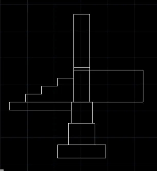
RESULT
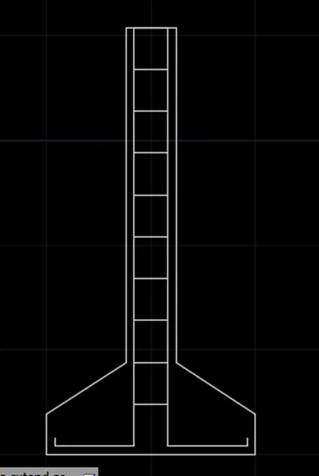
AIM
To create the following footing detail using AutoCAD
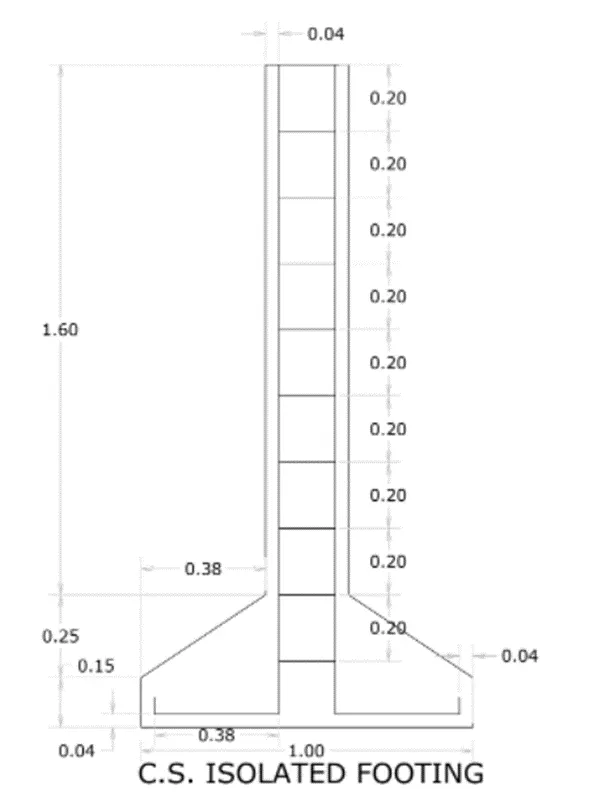
PROCEDURE:
Enter LINE command: L [Enter]
LINE specify first point: 1,1
Specify next point or [Undo]: @1,0
Specify next point or [Undo]: @0,0.19
Specify next point or [Undo or Close]: @-0.38,0.25
Specify next point or [Undo or Close]: @0,1.6
Specify next point or [Undo or Close]: @-0.16,0
Specify next point or [Undo or Close]: @0,-1.6
Specify next point or [Undo or Close]: @-0.38,-.25
Specify next point or [Undo or Close]: c
Enter OFFSET command: O [enter]
OFFSET specify offset distance: 0.04
Select object to offset or [Exit Undo]: select left 1.6 units line
Specify point on side to offset [Exit Multiple Undo]: click on the right
Select object to offset or [Exit Undo]: select right 1.6 unit line
Specify point on side to offset [Exit Multiple Undo]: click on the left
Select object to offset or [Exit Undo]: select bottom line
Specify point on side to offset [Exit Multiple Undo]: click above it
Join the two vertical lines
Enter OFFSET command: O [enter]
OFFSET specify offset distance: 0.2
Select object to offset or [Exit Undo]: select the new created line
Specify point on side to offset [Exit Multiple Undo]: M then click below it 9 times
Extend the reinforcement to meet the bottom reinforcement
Enter EXTEND command: EX
EXTEND select object: select the bottom line
EXTEND: select the vertical reinforcement to join it with the below reinforcement
Enter TRIM command: TR
TRIM select object: enter
TRIM: select the part to trim
RESULT
AIM
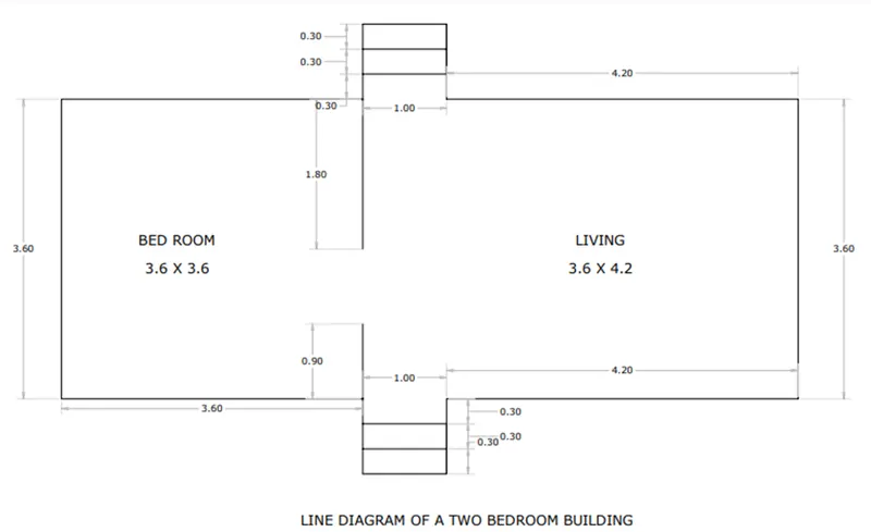
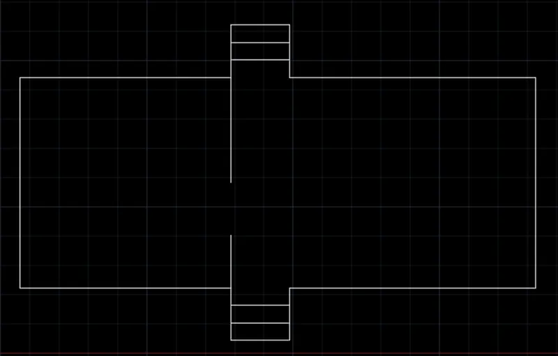
To create the following line diagram using AutoCAD
PROCEDURE:
Enter LINE command: L
LINE Specify first point: 1,1
LINE specify next point: @3.6,0
LINE specify next point: @0,-0.9
LINE specify next point: @1,0
LINE specify next point: @0,0.9
LINE specify next point: @4.2,0
LINE specify next point: @0,3.6
LINE specify next point: @-4.2,0
LINE specify next point: @0,0.9
LINE specify next point: @-1,0
LINE specify next point: @0,-0.9
LINE specify next point: @-3.6,0
LINE specify next point: c
Enter OFFSET command: O
OFFSET specify offset distance: 0.3
Select object to offset: select the stairs to offset
Enter LINE command: L
Specify first point: click on the corner of stair
Specify next point: drag mouse down and type 1.8
Specify next point: ESC
Enter LINE command: L
Specify first point: click on the corner of stair
Specify next point: drag mouse up and type 0.9
Specify next point: ESC
RESULT
AIM
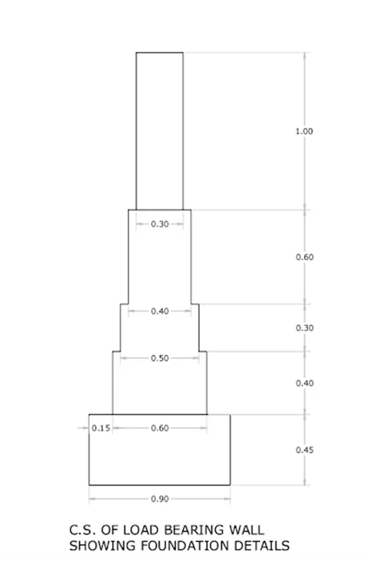
To create the following footing detail using AutoCAD
PROCEDURE:
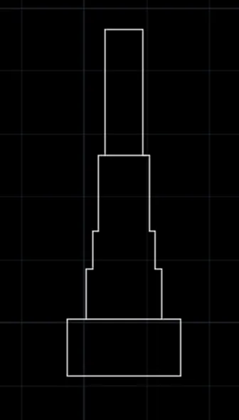
Enter LINE command: L
LINE Specify first point: 1,1
LINE specify next point: @0,0.45
LINE specify next point: @0.15,0
LINE specify next point: @0,0.4
LINE specify next point: @0.05,0
LINE specify next point: @0,0.3
LINE specify next point: @0.05,0
LINE specify next point: @0,0.6
LINE specify next point: @0.05,0
LINE specify next point: @0,1
LINE specify next point: @0.3,0
LINE specify next point: @0,-1
LINE specify next point: @0.05,0
LINE specify next point: @0,-0.6
LINE specify next point: @0.05,0
LINE specify next point: @0,-0.3
LINE specify next point: @0.05,0
LINE specify next point: @0,-0.4
LINE specify next point: @0.15,0
LINE specify next point: @0,-0.45
LINE specify next point: ESC
Enter LINE command: L
LINE Specify first point: join the tops and bottoms of the footing
RESULT
AIM
To create the following isometric view of stairs using AutoCAD
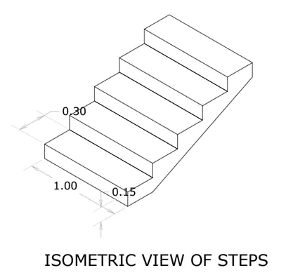
PROCEDURE:
Select isoplane left
Enter line command: L
Specify first point: click on the blank screen
Specify next point: drag the mouse and enter 1
Specify next point: drag the mouse up and enter 0.15
Specify next point: drag the mouse back and enter 1
Specify next point: drag the mouse down and enter 0.15
Select isoplane right
Enter line command: L
Specify first point: select the previous intersection point
Specify next point: drag the mouse right and enter 0.3
Repeat this from all 3 corners
Enter COPY command: CO
COPY select objects: Select all the lines
Specify base point: select the left most corner
Specify second point: select the continuing step of the stair
Repeat 5 times
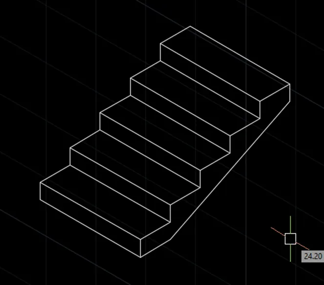
Enter LINE command
Specify first point: join the rest of the figure
Specify next point: ESC
RESULT
AIM
To create the following isometric view of wall using AutoCAD
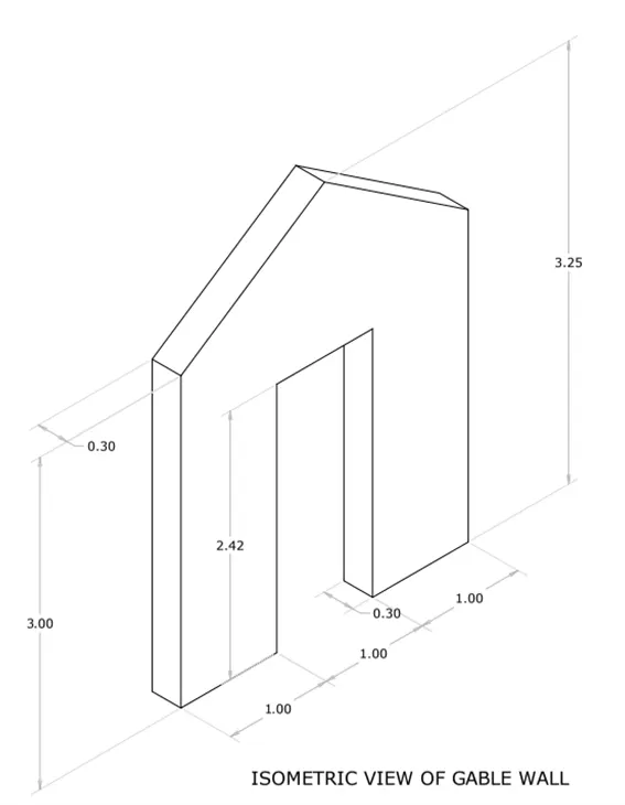
PROCEDURE:
Select isoplane right
Enter LINE command: L
Specify first point: click on the blank screen
Specify second point: drag mouse to the right and type 1
Specify second point: drag mouse up and type 2.42
Specify second point: drag mouse to the right and type 1
Specify second point: drag mouse down and type 2.42
Specify second point: drag mouse to the right and type 1
Specify second point: drag mouse up and type 3
Enter OFFSET command: O
Specify offset distance: 0.3
Select object to offset: offset the vertical lines as in the figure
Select isoplane left
Enter LINE command: L
Specify first point: join the offset lines
RESULT