Week 2 Challenge
CHALLENGE 2
Aim: The main aim of this challenge is to gain the knowledge about the concept of design of a tension members and the various causes of failure of the tension members. And to determine the sizes that are required for the tension member is also learnt.
Introduction: A tension member is a member which transmits a direct axial pull between two points in a structural frame. A rope supporting a load or a cable in a suspension bridge is an obvious example of a tension member. There are however a few cases in which a member which is basically a tension member, may, also be subjected to a bending moment either due to the eccentricity of the longitudinal load or due to transverse loads acting in addition to the main longitudinal load.
A tension member may have bolted or welded end connections. The effective sectional area of a tension member is less than its gross-sectional area due to bolt holes. A tension member has its unique property that it does not buckle. A tension member undergoes elongation and can extend until it reaches its ultimate strength. As the tensile load reaches the ultimate load the member reaches a failure state. A member in tension can reach a failure state due to excessive elongation or by rupture of its section.
The analysis of a member subjected to tension is probably the most straight forward to all structural analysis. The design of a tension member essentially consists of ensuring that the provided cross sectional area is at least sufficient to resist the tensile load applied. The manner of jointing the member to other parts will influence the manner in which the tensile force is transferred into the member.
In the case of fastening by bolts, the presence of holes in the section of the member has a direct effect on the strength of the member. We consider this problem by knowing its gross and net sectional area. The gross area refers to the original cross-sectional area of the member and the net area refers to the reduced sectional area after deductions due to the presence of bolt holes.
In a tension member the effect of a hole amounts to absence of some material and hence amounts to loss of strength. It may also be realized that in the immediate vicinity of a boll hole stress concentrations will occur and the same will also be affected by the force applied by the bolt. However since steel is ductile, it is usual to neglect these effects and to determine the net sectional area simply by deducting the area of the bolt holes from the gross-sectional area.
While making such deductions it should be noted that most of the types of bolts are provided in clearance holes, the diameter of the hole being made slightly larger than the bolt diameter. The diameter of bolt hole is usually 2 mm larger than that of a bolt for bolt diameters up to 24 mm. The absence of some material at sections where bolt holes exist, one may expect that the member may fail at the smallest net section, i.e., across a line of holes.
Failure Modes for Tension Members:
A tension member is liable to fail in various modes and the section of the member should be designed to prevent failure by any of these modes
(i) Failure by yielding of the gross-section.
(ii) Failure of the net section by rupture.
(iii) Block shear failure in which a certain part of the member at the connected end is sheared out from the rest of the member.
For a safe design, the factored tension should be less than the design strength in tension which is the least of, the design strength in yielding design strength in rupture and the design strength in block shear.
Design Strength Due to Yielding of Cross-Section:
A tension member has to be designed so that its cross-sectional area is sufficient to resist the tensile load on the member. We generally make reference to gross and net section of the member. The gross- section means the original cross-section of the member.
The net section means the reduced section at a line of bolts and is equal to the gross-sectional area minus the allowance for bolt holes. Bolts are generally provided in clearance holes of diameter usually 2 mm more than the diameter of bolts (for bolt diameters up to 24 mm).
It may first appear that since some material is absent at the net section a failure is most likely at the net section only. But the important aspect in the design is, that it is desirable that the gross-section yields before ultimate stress is reached at the net section.
Block Shear Failure:
Tests have shown that connections of angles, plates and coped beams are liable to fail as a consequence of block shear. This is type of failure where the member develops a shear failure along a row of bolt holes parallel to the direction of the load along with a tension failure on a perpendicular face. Block failure of a plate connected to a gusset plate with two rows of bolts.
Design of Tension Member
- Net Area for tension member calculation problem
Calculate the net section area for the tension member as shown in Figure below. The plate size is 260 x 20 thick and Bolt size is 20 mm.
Plate – Drilled Hole
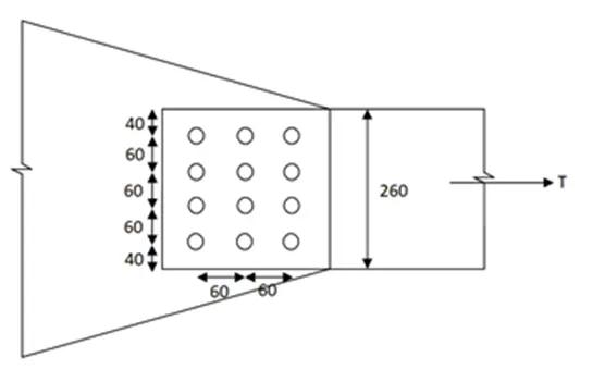
Ans: Net section area = (b - nd)t
b = 260mm : t = 20mm
d = 20 mm but, do = 20+2 = 22mm
n = 4
An = (260 - 4(22))20 = 3440mm2
Plate – Zigzag bolting
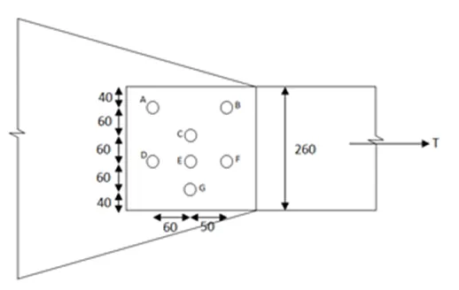
Ans: Net section area = (b - nd + sum(P2/4g))t
b = 260mm : t = 20mm
d = 20 mm but, do = 20+2 = 22mm
Case 1: Along section AD or BF : An = (260 - 2(22))20 = 4320mm2
Case 2: Along section CEG : An = (260 - 3(22))20 = 3880mm2
Case 3: Along section ACEG : An = (260 - 4(22) + 60^2/4(60) )20 = 3740mm2
Case 4: Along section BCEG: An = (260 - 4(22) + 50^2/4(60) )20 = 3648.33mm2
Case 5: Along section ACF: An = (260 - 3(22) + 60^2/4(60) + 50^2/4(60))20 = 3948mm2
The minimum value is the net section area, Hence An = 3648.33 mm2
Angle (200 x 100 x 12 with M20 bolt)
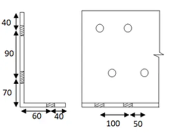
Ans: We know, Net section area = (b - nd + sum(P2/4g))t
Given, angle section: 200mmX100mm : t = 12mm
d = 20 mm but, do = 20+2 = 22mm
An = (200+100 - 3(22) + 50^2/4(90) + 50^2/4(130) ) 12 = 2949.02mm2
- Sag rod design problem
Design a sag rod as shown in Figure below. Purlins are supported at 1/3rd points by sag rods.
Assume centre to centre distance of Rafter spaced at 8 m, spacing of purlin = 1.2 m, Self-weight of roofing (including thermal insulation) = 60 kg/m2, Wind pressure intensity = 150 kg/m2, Slope of rafter = 15 degrees, Live Load =75 kg/m2. Assume self-weight of purlin as 100 kg/m.
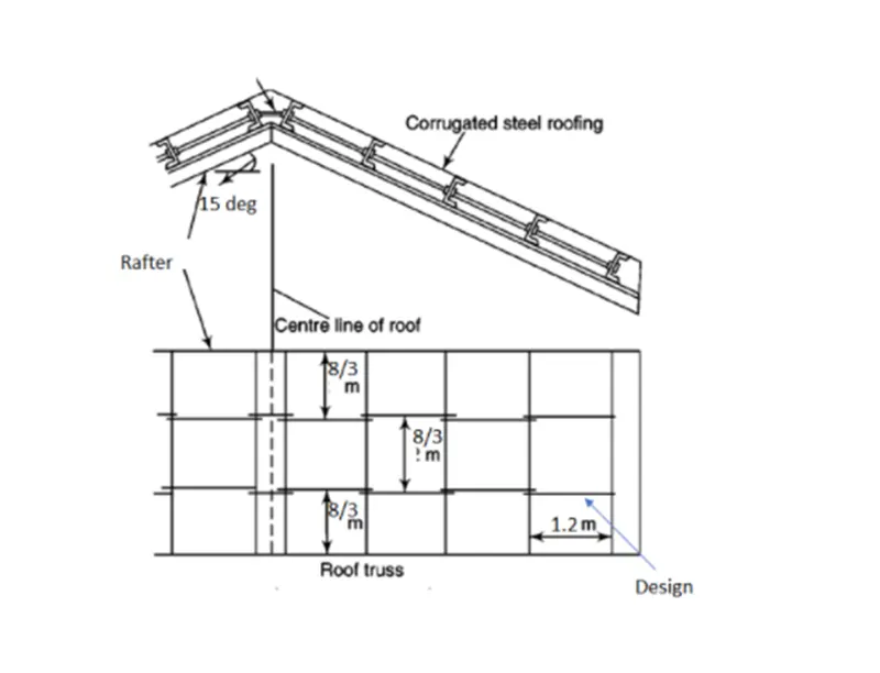
Ans: DL + LL = (60+75)*9.8*1.2*8 = 12700
Load on each sag rod = (12700/3 + 100*9.8*8/3) Sin (15) = 6846.66*Sin (15) = 1772 N
Load on threaded rod, Tdn= 0.9*An*fu/1.25
1772 = 0.9*An*fu/1.25
An = 1772*1.25/ (0.9*250) (fu = 250 Mpa)
An = 9.844
d = (4*An/pi) ^0.5
d = 3.54 mm
- Determine section size for given tensile load
Design a single angle member of length 5m to carry axial tensile force of 500 kN. Yield strength fy of the material to be considered is 350 N/mm2.
Ans: Assume 4mm weld size , fy = 250MPa, fu = 410 Mpa
Approximate gross area = 1.1Tdg/fy = 1.1 x 250 x 1000/250 = 1100 mm^2
From steel table, select ISA 100x75x8mm connected to gusset plate by longer length Cxx
Area of connected leg = ( 100 - 8/2) x 8 = 768mm2
Area of outstanding leg = ( 75 - 8/2) x 8 = 568mm2
Ag = 768+568 — 1336mm2 > 1100mm2
Hence Safe.
Design strength due to yielding of gross section
Tdg = Agfy/rmo = 0.91 x 1336 x 250 11000 = 303.94kN
Design strength due to rupture at net section
Tdn = alpha*An*fu/rml
fu = o.8x1336x410/1000
fu = 438.21 KN
Design strength due to block shear
For calculation of block shear, length of weld is required
P1 x 100 = 250 x (100 -31) = 172.50KN
P2 = 250 - 172.50 = 77.5 KN
Strength of 4mm weld = 0.7 x 4 x 0.462 x 410 = 530.37 kN/mm
Effective length of weld on head side = 172.5 x 1000/530.37 = 325mm
Effective length of weld on toe side = 77.5 x 1000/530.37 = 146mm
Total welded length = 325 + 146 = 471mm
Avg = Avn = 471 x 8 = 3768 mm2
Atg = Atn = 100 x 8 = 800mm2
Tdb1 = 0.525Avg x fy + 0.72 x Atn x fy = 0.525 x 3768 x 250/1000 + 0.72 x 800 x 410/1000 = 730.31kN
Tdb2 = 0.416 Avn x fu + 0.91 x Atg x fy = 0.416 x 3768 x 410/1000 + 0.91 x 800 x 250/1000 = 824.67KN
Tensile strength provided = 438.21kN, 303.94KN and 730.71KN > 250KN
Hence safe.
Conclusion:
From the project carried out it can be concluded that the concept of the design procedure of the tension member and the various reasons for the failure of the tension member is learnt. The method for the determination of the size of the tension member is also learnt. The concept of the determination of the net tensile area of a member is also learnt.
Vijayalakshmi S H