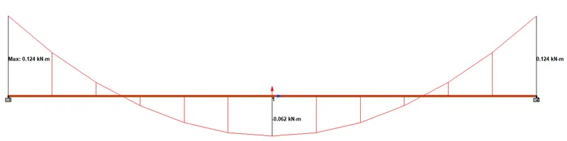
Week 2 Challenge
1. 1. How will you assign Circular section to column?
Ans:
- After created a Geometry of a model, Click Properties option and select the Circle from property tab.
- Followed by input values for YD and select appropriate Material for circular section.
2. How will you assign Unit system to a .std model file?
Ans:
- To assign Unit system to a .std model file, we can select the appropriate Unit system in Model Information while creating New Model.
- Or we can also change the Unit system from the existing model, for that Click inside the Search box at Menubar and type Unit and select Set Current Input Units.
3. What are the parameters to be specified while using “Bay Frame” option?
Ans:
The Parameters to be specified while using "Bay Frame" option are :
- Length.
- Height.
- Width.
- No. of Bays along Length.
- No. of Bays along Height.
- No. of Bays along Width.
4. Name few codal standards incorporated in STAAD Pro software.
Ans:
- Indian Standards (IS) code
- EuroCode (EC)
- American Standards Code (AISC)
5. How will you specify the design compressive strength for a RCC section?
Ans:
To specify the design compressive strength for a RCC section,
- Click Design option and change Current Code as IS 456 (concrete) then Select Define Parameters.
- From opened Define Parameters tab, select FC to specify the design compressive strength for Concrete section.
- Likewise for Steel, the Current code should be changed as IS 800 (Steel) and select FYLD parameter for a Steel section.
2. 1. State the “Input” steps involved in RCC design.
Ans:
- Geometry - Here we create a Geometry of the appropriate model.
- Properties - Here we input the dimensions of the created Geometry.
- Materials - Here we assign the appropriate material property to the created Geometry.
- Specifications - Here we can specify the structural moments in any directions by releasing appropriate forces and moments.
- Supports - Here the appropriate supports for the created Geometry will be added and assigned to the model.
- Loading - Here we can add and assign approriate loads for the created model as per its properties such as Dead Load, Live load etc.
- Analysis - Here we can Run the analysis of the created Model along with its appropriates and find out its Defomation.
- Design - Here we can select the appropriate Codes for the model properties and Define its parameters then can assign it.
2. Explain the difference between Fixed and Enforced support condition in STAADPro.
Ans:
FIXED SUPPORT CONDITION:
- When the Fixed type of support is specified, for those degrees of freedom which are to be treated as fully restrained. STAAD assumes the displacements to be known quantities whose value is Zero. Hence, those degrees of freedom are not considered for the stiffness matrix, and their value is not calculated.
ENFORCED SUPPORT CONDITION:
- When the Enforced type of support is specified, for those degrees of freedom which are to be treated as restrained, STAAD assigns a spring with a spring stiffness - translational stiff springs for translational restraints, and rotational stiff springs for rotational restraints. Those degrees of freedom which are free to display are assigned springs of Zero stiffness. Hence, for all the 6 degrees of freedom at such supports, the displacements are calculated. The ones which have a stiff spring will end up having a negligible displacement, and those with Zero-stiffness-springs will have a displacement based on the structure geometry, properties and loading.
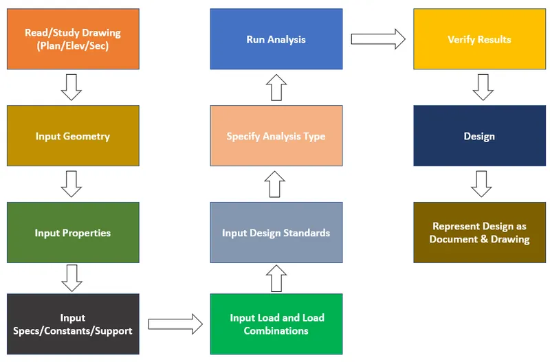
3. 1. Explain the steps involved in analysis of a model using STAAD Pro sequentially.
Ans:
2. Explain the two ways in which a structural framework/model can be created in STAAD Pro software.
Ans:
The two ways in which Structural Model can be created are :
- Node Cursor - Here by selecting Node Cursor, we can input nodes at appropriate directions and creating frame by connecting the nodes.
- Structure Wizard - Here the whole structural Framework can be created by selecting appropriate Model Type and Parameters.
3. Elaborate the different support conditions in STAAD Pro.
Ans:
To evoke supports, click Supports option and select Create to see all available support conditions in STAAD Pro.
- Fixed Support - Here all the six degrees of freedom are in restrained condition.
- Pinned Support - Here three degrees of freedom of Moments(M) are in released condition and three degrees of freedom of Forces(F) are restrained condition.
- Fixed But - Here we can Release and Restraint the nodes appropriately as required. If we need Roller support means we can restraint FX and MZ and release remainings.
- Enforced Support - Here likewise as Fixed support all the six degrees of freedom are in restrained condition.
- Enforced But - Here aslo likewise as Fixced But, we can Release and Restraint the nodes appropriately as required.
4. How will you extract the stress distribution for a staircase slab?
Ans:
- Create the respective node of a Stair slab.
- Assign "Plate element" as slab property.
- Define load cases and calculate the area load acting on to the stair slab.
- Apply the load cases and combinations to the plate element as area load.
- Mesh the plate elements.
- Go for the "Analysis". Go to "Post Processing Mode".
- Select "Plate results - Plate stress contour".
- Under the stress type choose the appropriate stress type.
5. Explain the different ways to view SFD & BMD in STAAD Pro.
Ans:
- To view SFD & BMD in STAAD Pro. click Results option in MenuBar.
- Under the Stress type choose FX for the Shear force along X direction.
- Likewise choose MZ for the Bending Moment along Z direction.
- We can select different load cases such as Primary, Combination, Envelope and All.
Practical
1. Analyze the following structural elements and validate the results
A. ) Simply Supported Beam
a. A Simply supported beam with two point loads symmetrically placed
b. Span L = 20m
c. Load P = 50kN each
d. Both P located at 5m from each support
AIM & INTRODUCTION :
AIM :
To analyze and validate the results of Simply supported Beam with given structural elements by using STAAD Pro.
INTRODUCTION :
- In STAAD.Pro we can create a various structural models.
- We can assign the appropriate properties to the created model.
- Also the supports to can also be assigned at the corners of the structural model.
- Here in STAAD we can apply the appropriate load cases on the created model and Analyse it.
- It will show us the exact displacement of the structure as per its properties and supports.
- In Result we can see the SFD and BMD of the applied Load cases.
PROCEDURE :
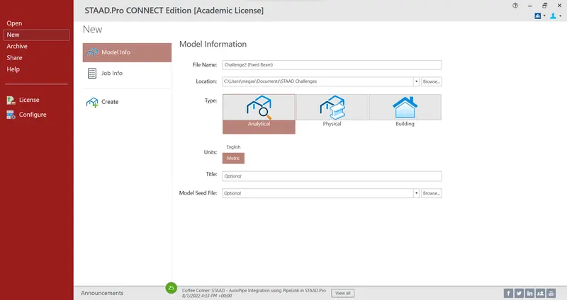
- Open STAAD.Pro software, Select New and in Model Info input appropriate File name, Location, Type, Units, Title.
- Then Click Create to open a Workspace to start creating a Structural Model.
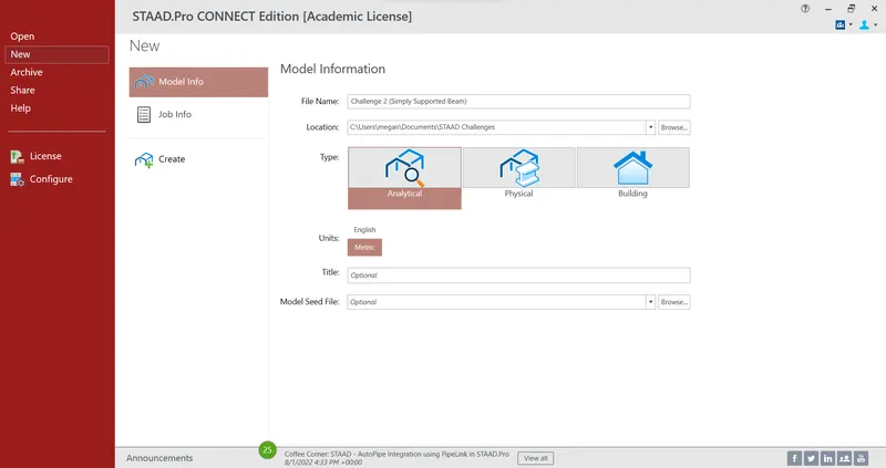
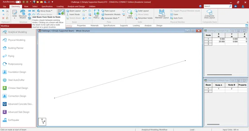
- After opening a New file to create a structural model, in Geometry input appropriate span length at the Nodes Tab at the right top corner.
- At the Nodes Tab input Node 1 = 0m and Node 2 = 20m in X axis.
- Here we can see the two Node points are created at a distance of 20m along X axis.
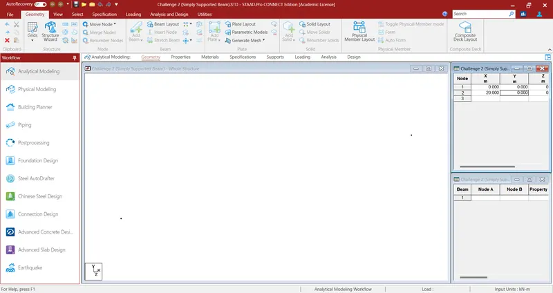
- Then select Add Beam icon at the Toolbar to create a Beam with a span length of 20m by connecting two Nodes.
- After adding a beam in Geometry, Select Properties and click Define to open a Property Tab.
- From the opened Tab select Rectangle < YD = 0.45m, ZD = 0.45m and Material = Concrete.
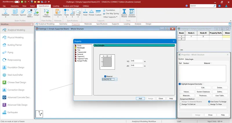
- Then Click Add and select the defined Property and Assign it to view by clicking Assign.

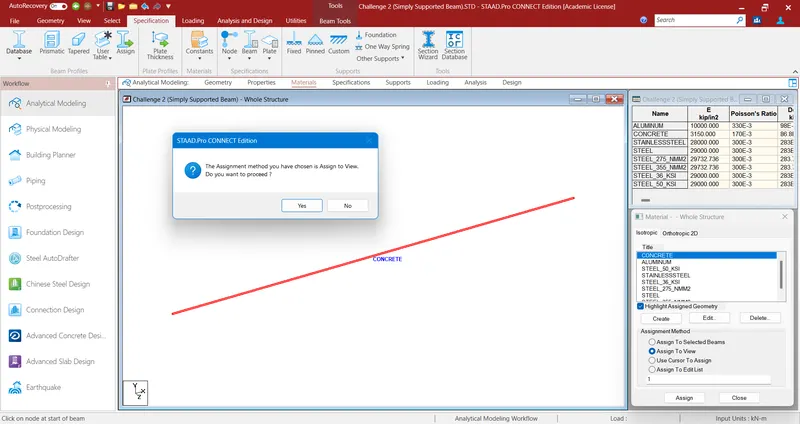
- Then Click Materials, Select the appropriate material such as Concrete and Assign it to the view by clicking Assign.
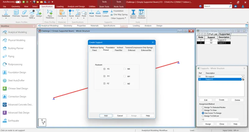
- Then Click Supports, Select the appropriate Support such as Pinned for simply supported.
- Click Add and Assign it to the view at the two ends of the beam by clicking Assign.
- Followed by supports, Click Loading < select Load Cases Details and click Add to open a Tab to Add New - Load cases.
- Here in primary < input Loading Type = Dead, Title = DL and click add.
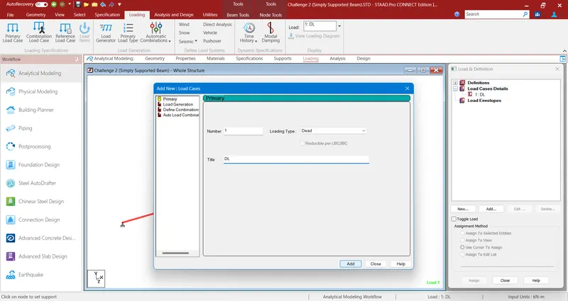
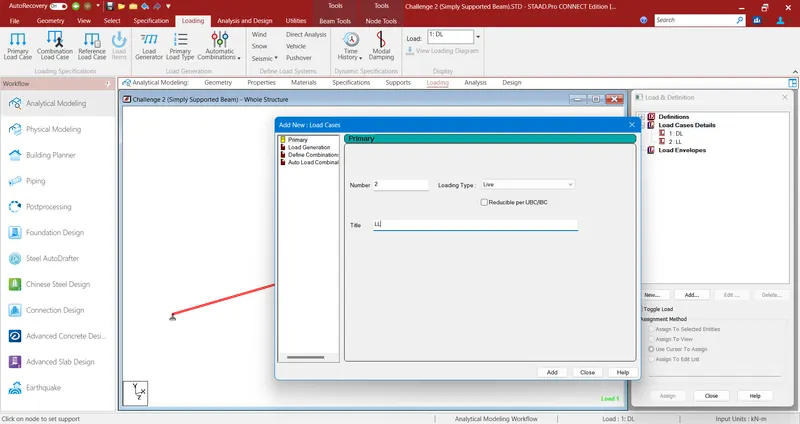
- Likewise for Live Load, Click Loading < select Load Cases Details and click Add to open a Tab to Add New - Load cases.
- Here in primary < input Loading Type = Live, Title = LL and click add.
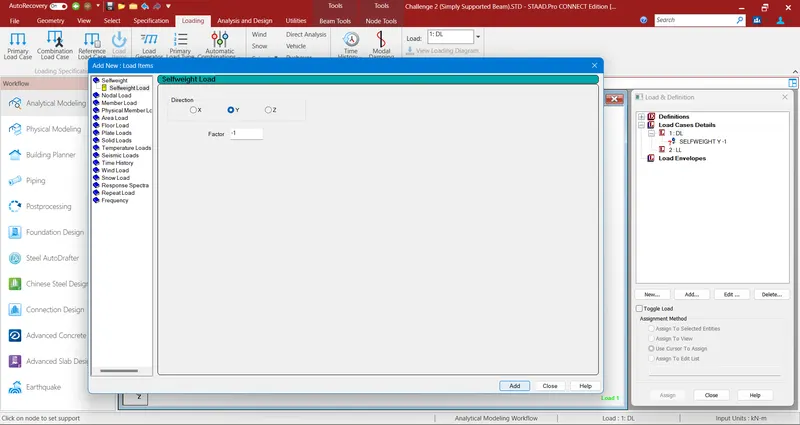
- After Adding Dead Load, select it and add a Selfweight Load as -1.
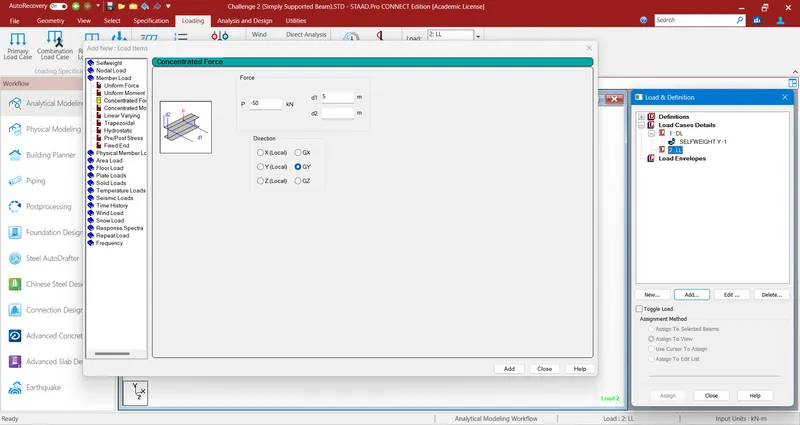
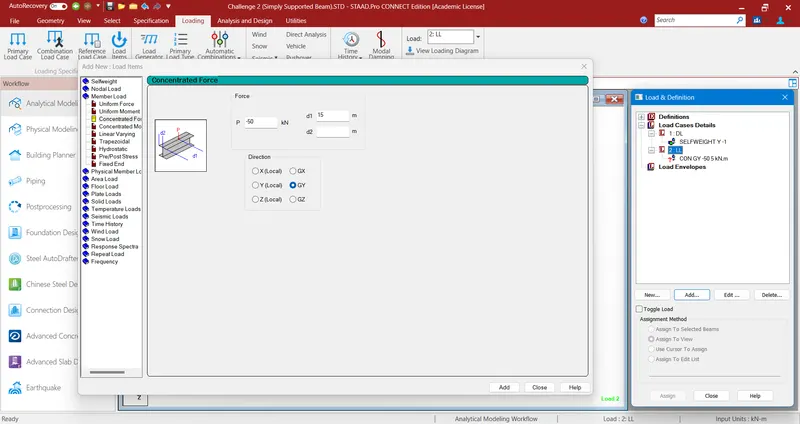
- Lisewise for added Live Load, select it and add Concentrated Force P = -50N, d1=5m and Direction = GY.
- Add another Live Load at different distance as required, for that select Added Live Load and add Concentrated Force P = -50N, d1=15m and Direction = GY.
- At last Select and Assign the Added SelfWeight and Concentrated Force to the View.
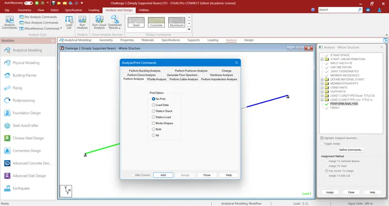
- Then go to Analysis and click Analysis Commands to open a Analysis/Print Commands Tab.
- After opening of the Tab, Select No Print and click Add to add the Perform Analysis command.
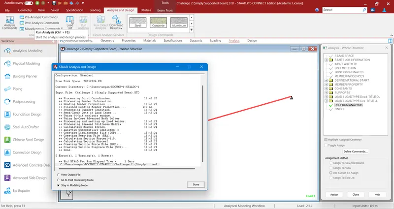
- Then Click Run Analysis icon present at the Toolbar to start Analysis of the created Model with assigned Properties.
- Here we can see the Configuration Standard of the Analysis Run along with its Errors, Warnings and Notes.
- After completion of the Analysis, select Go to Post Processing Mode and click Done.
- Before moving to the Post Processing Mode, it Shows us the Result Setup to select the Available Load Cases to view Load Diagrams.
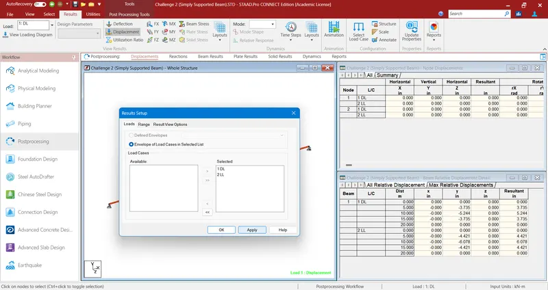
- In Results, from the selected Displacement option we can Select FY (Shear Force in Y axis) to View SFD of the Analysed Structural Element.
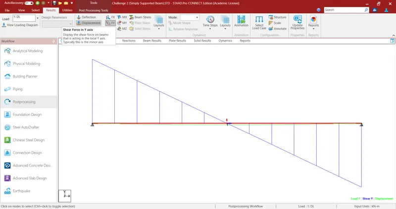
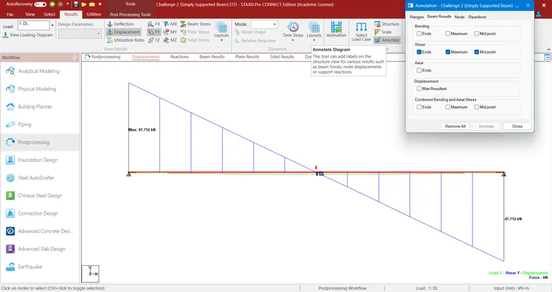
- Here in SFD (Shear Force Diagram) we view the Beam Result Values, fpr that Select Annotate icon to open Annotation Tab.
- And Select the Check boxes below the Shear and click Annotate to enable the values to appear at the SFD.
- Likewise in Results, from the selected Displacement option we can Select MZ (Bending moment about Z axis) to View BMD of the Analysed Structural Element.
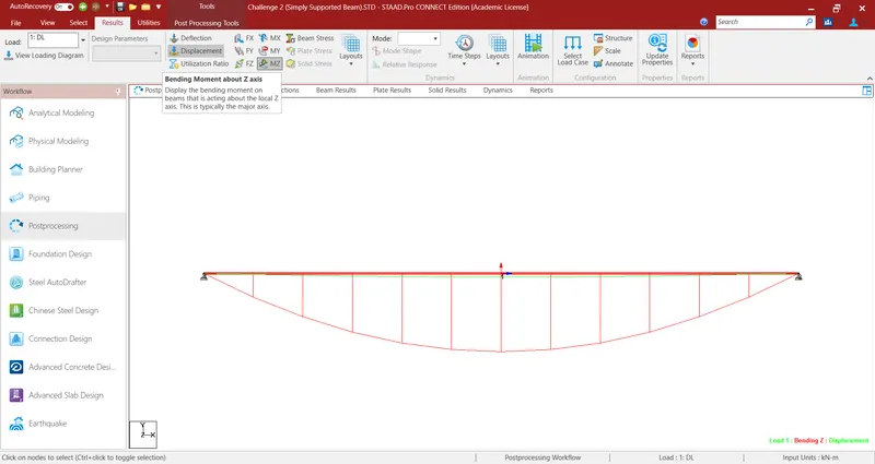
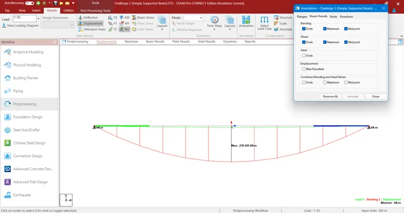
- Here in BMD (Bending Moment Diagram) we view the Beam Result Values, for that Select Annotate icon to open Annotation Tab.
- And Select the Check boxes below the Bending and click Annotate to enable the values to appear at the BMD.
RESULT :
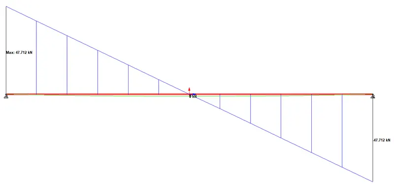
SFD of the Simply Supported beam :
- Here in SFD (Shear Force Diagram), we can see the Shear in Y axis due to the applied Load Cases.
- The Maximum applied load at a particular distance from the each ends carries a Balanced Shear at both sides with its Pinned supports at both the ends.
BMD of the Simply Supported beam :
- Here in BMD (Bending Moment Diagram), we can see the Bending Moment along Z axis due to the applied Load Cases.
- The Maximum applied load at a particular distance from the each ends carries a total Deflection at the center for the model with its Pinned supports at both the ends.

B. ) Fixed Beam
a. Span L = 16m
b. Uniformly Distributed Load w=9kN/m
AIM & INTRODUCTION :
AIM :
To analyze and validate the results of Fixed Beam with given structural elements by using STAAD Pro.
INTRODUCTION :
- In STAAD.Pro we can create a various structural models.
- We can assign the appropriate properties to the created model.
- Also the supports to can also be assigned at the corners of the structural model.
- Here in STAAD we can apply the appropriate load cases on the created model and Analyse it.
- It will show us the exact displacement of the structure as per its properties and supports.
- In Result we can see the SFD and BMD of the applied Load cases.
PROCEDURE :
- Open STAAD.Pro software, Select New and in Model Info input appropriate File name, Location, Type, Units, Title.
- Then Click Create to open a Workspace to start creating a Structural Model.
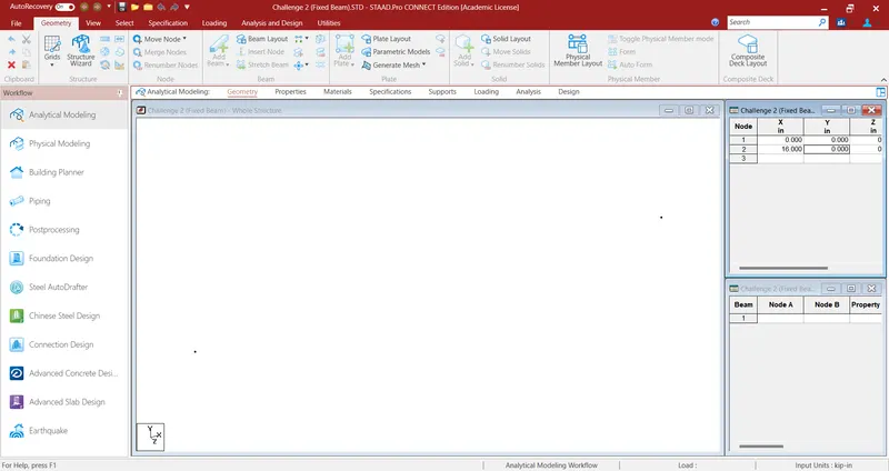
- After opening a New file to create a structural model, in Geometry input appropriate span length at the Nodes Tab at the right top corner.
- At the Nodes Tab input Node 1 = 0m and Node 2 = 16m in X axis.
- Here we can see the two Node points are created at a distance of 16m along X axis.
- Then select Add Beam icon at the Toolbar to create a Beam with a span length of 16m by connecting two Nodes.
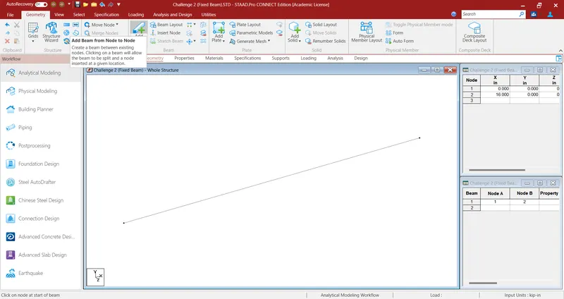
- After adding a beam in Geometry, Select Properties and click Define to open a Property Tab.
- From the opened Tab select Rectangle < YD = 0.6m, ZD = 0.6m and Material = Concrete.
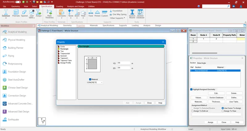
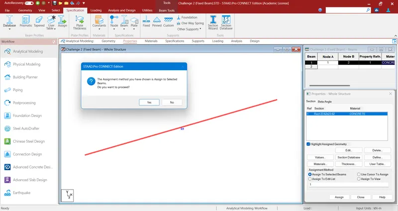
- Then Click Add and select the defined Property and Assign it to view by clicking Assign.
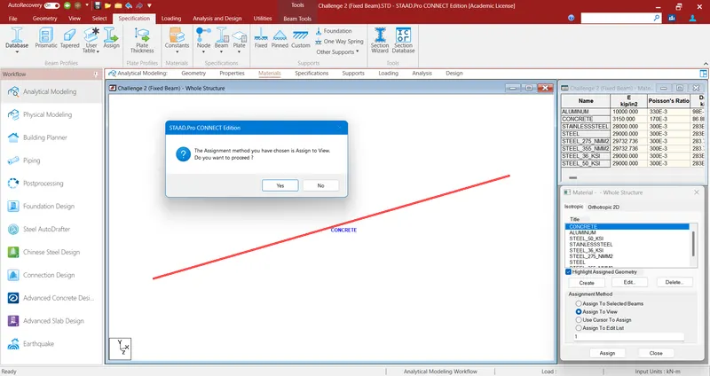
- Then Click Materials, Select the appropriate material such as Concrete and Assign it to the view by clicking Assign.
- Then Click Supports, Select the appropriate Support such as Fixed for Fixed Beam.
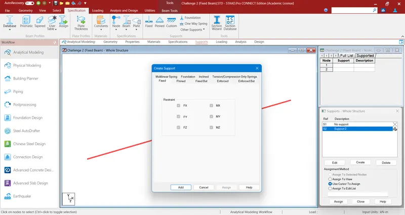
- Click Add and Assign it to the view at the two ends of the beam by clicking Assign.
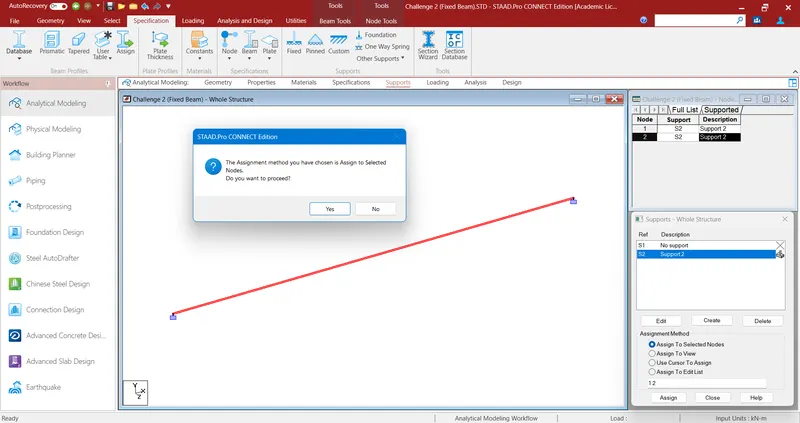
- Followed by supports, Click Loading < select Load Cases Details and click Add to open a Tab to Add New - Load cases.
- Here in primary < input Loading Type = Dead, Title = DL and click add.
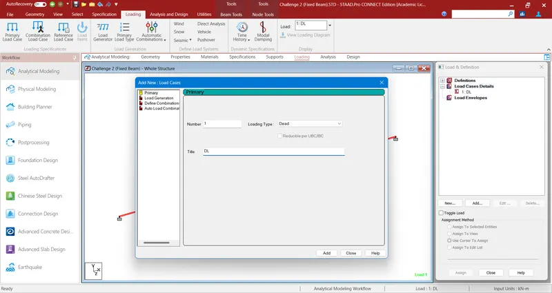
- Likewise for Live Load, Click Loading < select Load Cases Details and click Add to open a Tab to Add New - Load cases.
- Here in primary < input Loading Type = Live, Title = LL and click add.
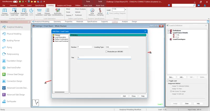
- After Adding Dead Load, select it and add a Selfweight Load as -1.
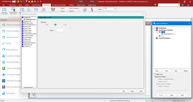
- Lisewise for added Live Load, select it and add Uniform Force W1 = -9N, d1=0m and Direction = GY from Member Load.
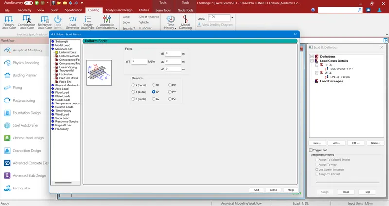
- At last Select and Assign the Added SelfWeight and Uniform Force to the View.
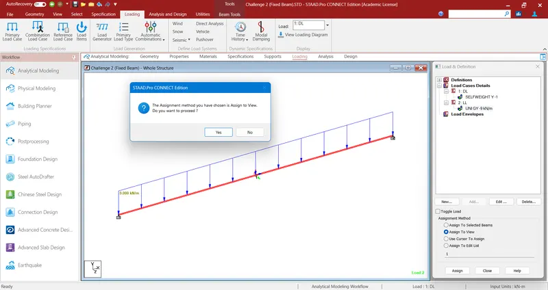
- Then go to Analysis and click Analysis Commands to open a Analysis/Print Commands Tab.
- After opening of the Tab, Select No Print and click Add to add the Perform Analysis command.
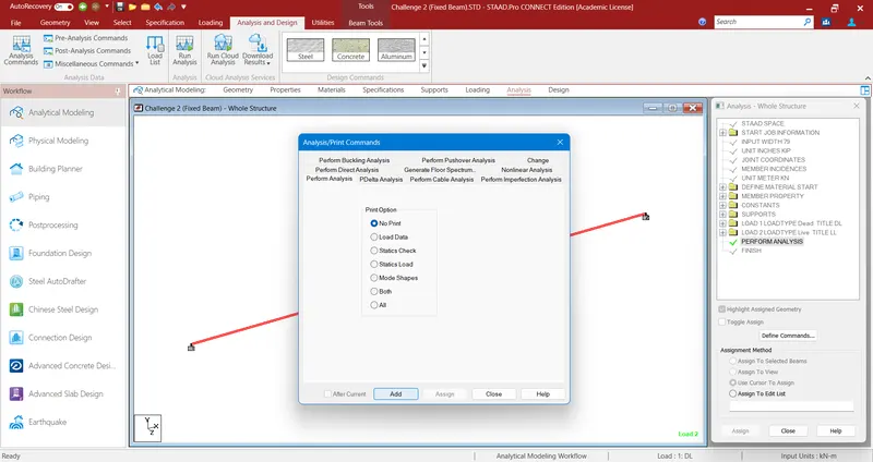
- Then Click Run Analysis icon present at the Toolbar to start Analysis of the created Model with assigned Properties.
- Here we can see the Configuration Standard of the Analysis Run along with its Errors, Warnings and Notes.
- After completion of the Analysis, select Go to Post Processing Mode and click Done.
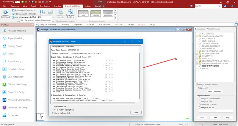
- Before moving to the Post Processing Mode, it Shows us the Result Setup to select the Available Load Cases to view Load Diagrams.
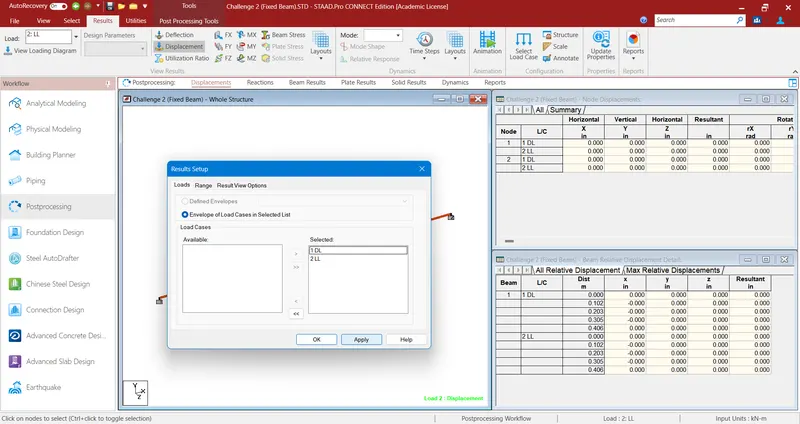
- In Results, from the selected Displacement option we can Select FY (Shear Force in Y axis) to View SFD of the Analysed Structural Element.
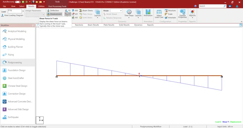
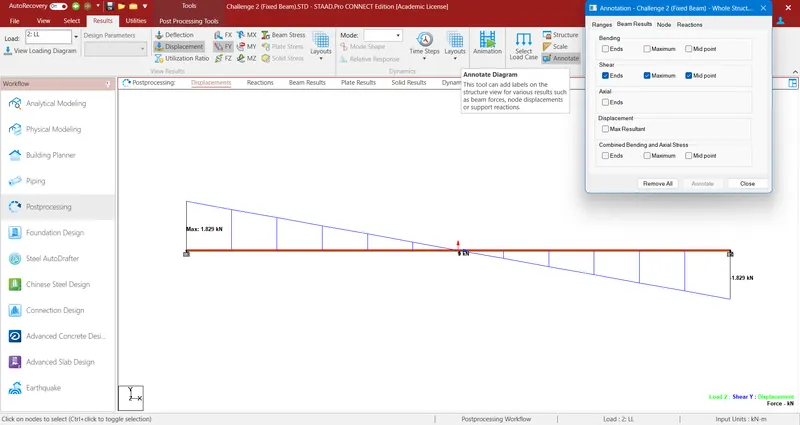
- Here in SFD (Shear Force Diagram) we view the Beam Result Values, fpr that Select Annotate icon to open Annotation Tab.
- And Select the Check boxes below the Shear and click Annotate to enable the values to appear at the SFD.
- Likewise in Results, from the selected Displacement option we can Select MZ (Bending moment about Z axis) to View BMD of the Analysed Structural Element.
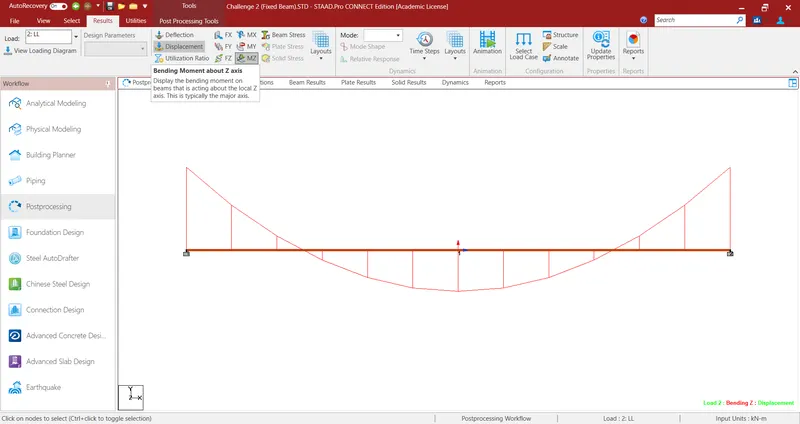
- Here in BMD (Bending Moment Diagram) we view the Beam Result Values, for that Select Annotate icon to open Annotation Tab.
- And Select the Check boxes below the Bending and click Annotate to enable the values to appear at the BMD.
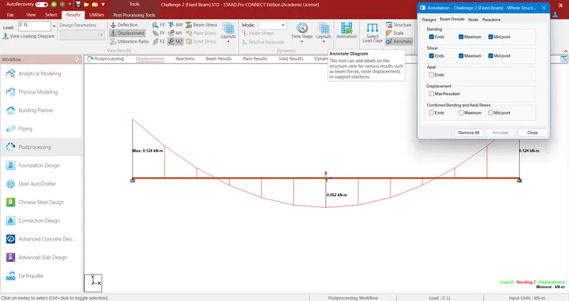
RESULT :
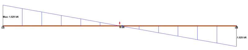
SFD of the Fixed beam :
- Here in SFD (Shear Force Diagram), we can see the Shear in Y axis due to the applied Load Cases.
- The applied Uniform load along all over the span carries a Balanced Shear at both sides with its Fixed supports at both the ends.
BMD of the Fixed beam :
- Here in BMD (Bending Moment Diagram), we can see the Bending Moment along Z axis due to the applied Load Cases.
- The applied Uniform load along all over the span carries a total Deflection at the center for the model with its Fixed supports at both the ends.