Week 2 Challenge
1st Answer:
BIM stands for BUILDING INFORMATION MODELING.BIM is a new process and methodology by which a team of architects,engineers and contractors work collaborately to design and build a commercial building utilizing the same database and computer model.BIM offers a more complete representation of a buidings design.BIM allows you to design electrical and HVAC systems,as well as building itself.BIM pulls your documents to a single database.several people can work on same model and save it to cloud.resource tracking is a key component of BIM models.we can easily figure out how much of each resource we need during the design stage.this improves the flow and efficiency of construction.
BENEFITS OF BIM OVER 2D CAD TOOLS:
CAD is typically used for industral design of mechanical and electrical assemblies.while BIM is used exclusively in design and construction of commercial buildings such as airports,office,towers and has more increasingly become the new standard.BIM can expand on basic CAD designs,providing more information to project stakeholders in the process.
2nd Answer:
AIM: To Understand the concept of Categories, Families, Elements, Instances in Revit.
TOOLS REQUIRED:Insert,Load Family,Instances.
PROCEDURE:
a)open a new project and design a sample wall and design a door to it.now go to INSERT toolbar.
b)locate LOAD family in the insert toolbar.then click on it.
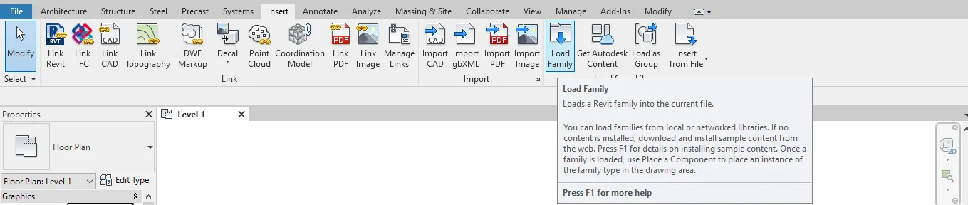
c)it is directed to the contents that have been downloaded in the my computer like doors,walls etc.
d)for example,take doors.we have many other like walls,columns,ducts etc in which doors is one category.
e)when we click on doors,we can see different types of doors like single flushed,double flushed,glass doors etc.which are considered whole as a family.
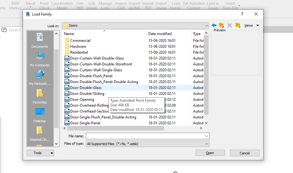
f)select one of the type of the door which is considered as a element.each type of door is considered as a seperate element.
g)now select an element with all the dimensions and click ok.
h)select the door that you have designed first.you will be able to see the properties. select that door and you will be able to see the properties of doors.select the required door and dimensions and click on it.
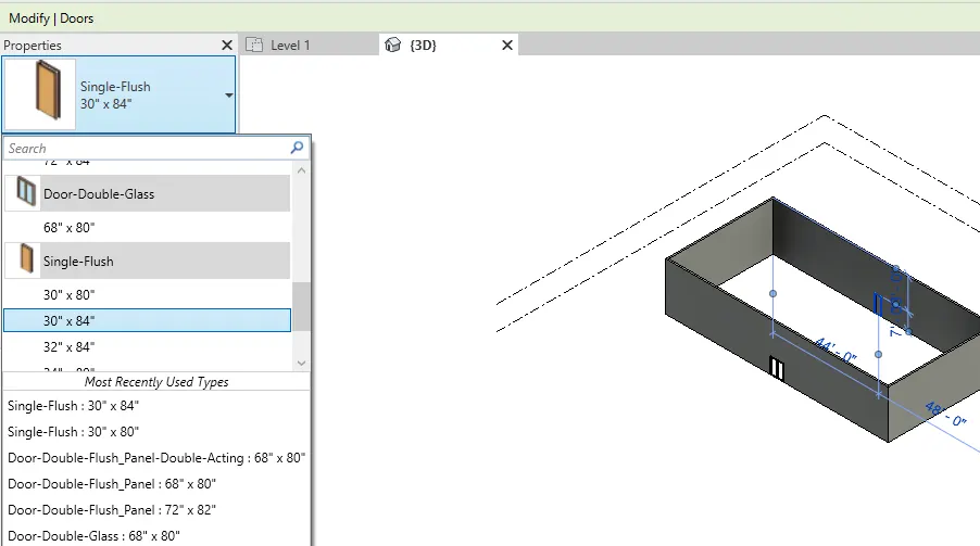
i)now we can see the door and dimensions has been changed.
RESULT:We understood the concept of categories,families,elements and instances in revit.
3rd Answer:
AIM:to open a imperial architectural template,saving the file,completing project information and setting maximun backups to 3.
TOOLS REQUIRED:file,project information.
PROCEDURE:
a)first open the revit software.we can find NEW option in the model window.click on new.
b)select architectural template in the templates and click ok.
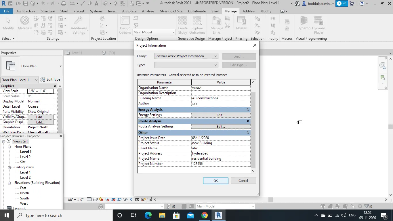
c)now,go to manage toolbar and you can find project information .click on it.you can change/name the organisations,client name,issue date etc.and click ok to save the project information.
d)to save the file,go to file toolbar and click save as in it.we get project.click on it.
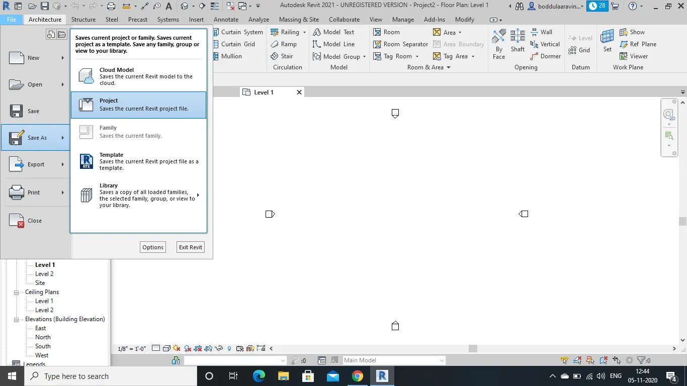
e)we are directed to save the file,where we can change the file name.
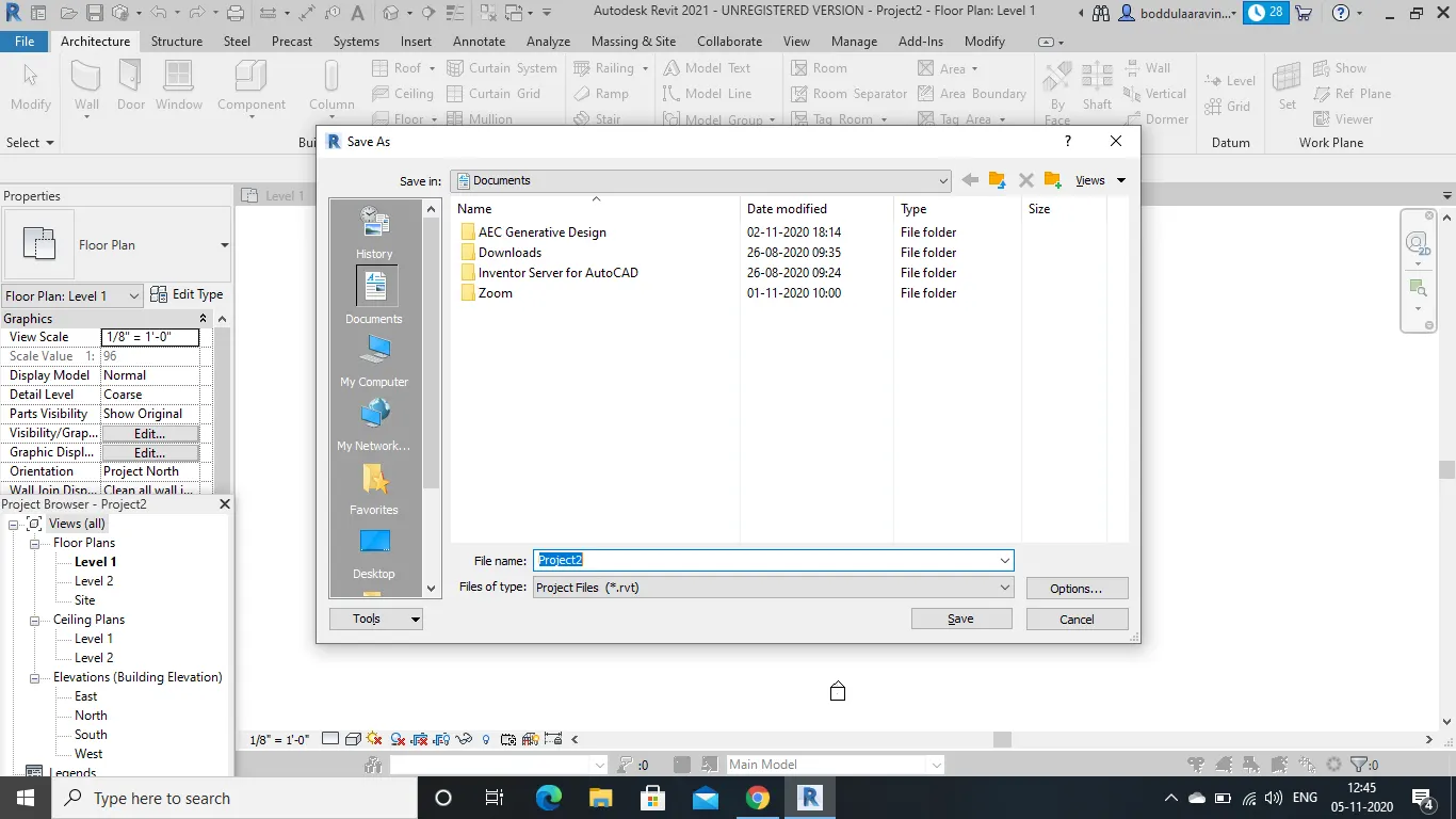
f)we have options option above the cancel option.click on it to change the maximum backups to 3.we can see the maximum backups there and enter 3 and click ok.
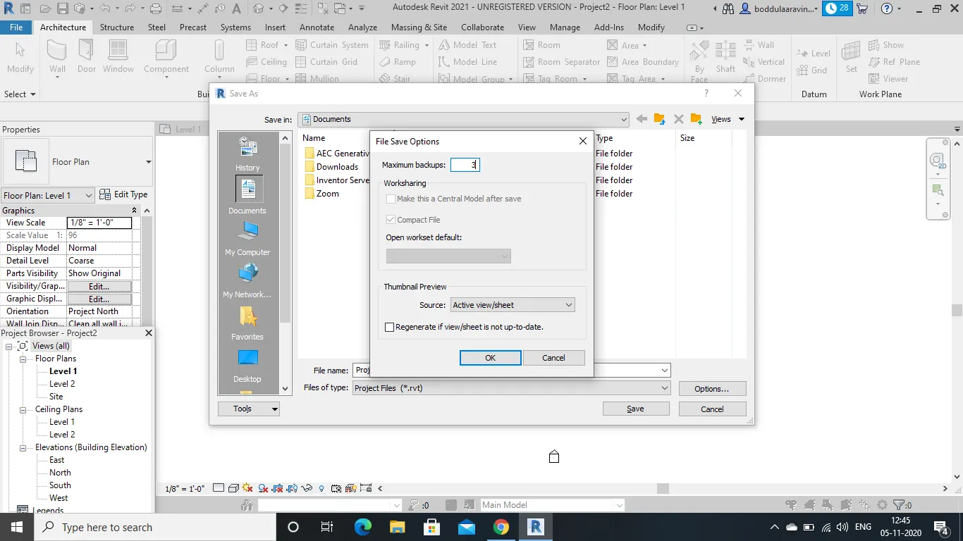
g)the click ok once again to save the file.
RESULT:an imperial architectural file has been opened,completed project information,maximum backups has been changed to 3 and file has been saved.
4th Answer:
Revit LEVELS and GRIDS are the skeleton of building projects.typically the levels in revit are used to indicate the locations the location of floors,foundations and the roof of a building in section and elevation views.more recent versions of revit include levels in 3d views.Grids are used to host columns and walls.both levels and grids interact in a way that can cause some confusion if not set correctly.
A) AIM:To create the levels:
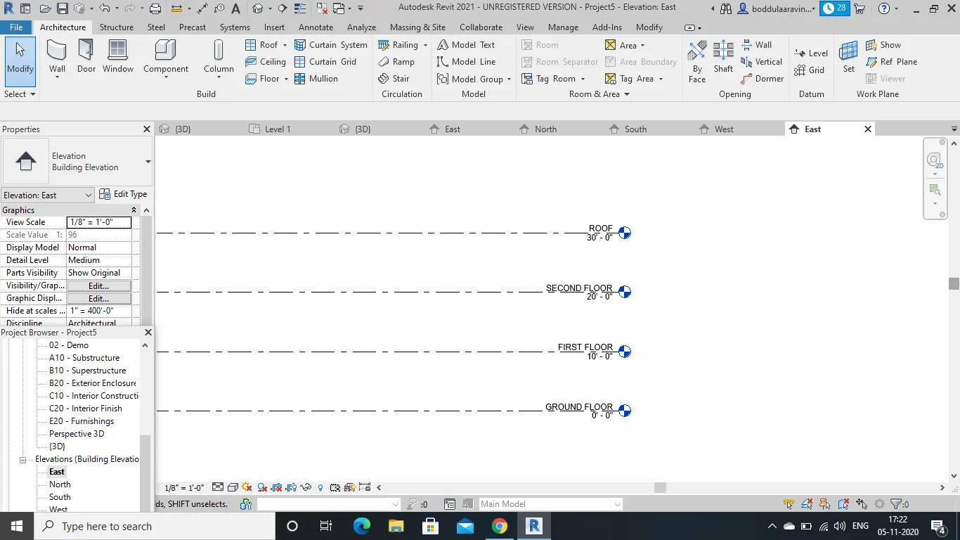
Ground Floor @ 0’
First Floor @ 10’
Second Floor @ 20’
Roof @ 30
TOOLS REQUIRED:Construction template,Elevations,Levels.
PROCEDURE:
a)create a new imperial construction template.
b)first click on elevations(in properties).select one of the elevations by double clicking(East,west,north,south).
c)after clicking east, we get view from east where we can find levels like footings,foundations,basement slabs,level1..etc.
d)remove the foundation levels and all other except the levels having 0'0",10'0",20'0".
e)now,to add the roof level(30'0"),click on architecture toolbar and select on LEVELS which is above the grid.
f)when we take the cursor to the design,we can see the height and according to the required dimensions,the level is created.
g)now,rename all the levels by double clicking on it as groundfloor,first floor,second floor,roof in the place of level1,leve;2,level3,level4 respectively.
RESULT:the required levels has been succesfully constructed.
B)AIM:to create the following levels:
Grids Transverse Grids A, B,C,D, E @ 10’ spacing
Longitudinal Grids from 1 to 10 @ 20’ spacing.
TOOLS REQUIRED:construction template,Elevations,Grids.
PROCEDURE:
a)create a imperial constructional template project.
b)open architectural toolbar in the menu.select grids which is in rightside.
c)after clicking it,we can draw grids in horizontal and vertical direction.
d)first draw horizontal grids(transversal grids) by maintaining 10'0" distance between them by naming a,b,c,d,e respectively.
e)draw vertical grids(longitudinal grids) by maintaining 20'0" distance between them by naming as 1,2,3,4,5,6,7,8,9,10 respectively.
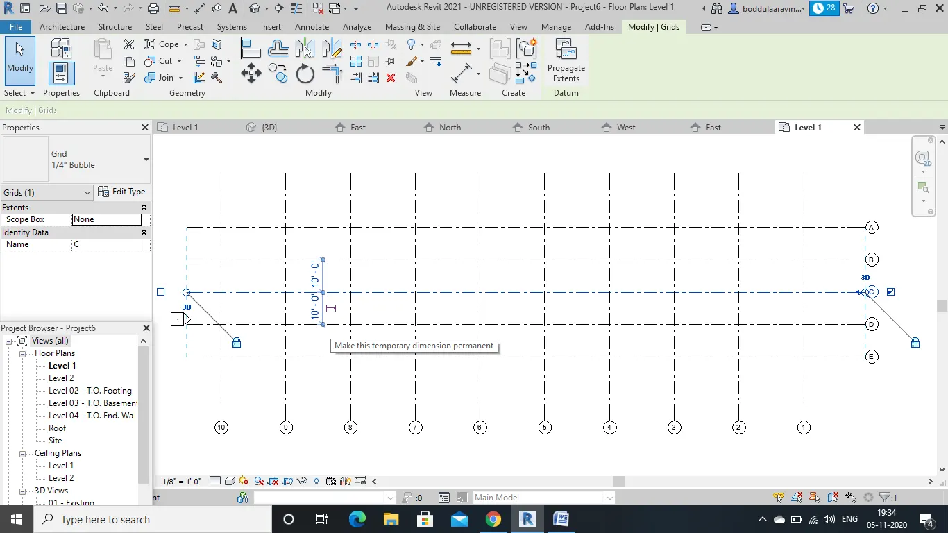
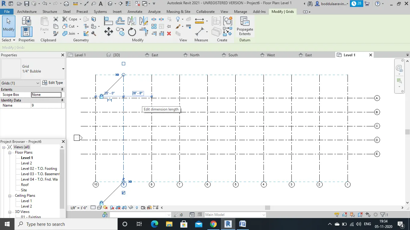
RESULT:the required levels has been constructed succesfully.
5th Answer:
AIM:To create a conceptual layout of the residential unit,to show the 3d view of residential unit and to measure it.
TOOLS REQUIRED:Wall,doors,3D view,linear.
PROCEDURE:
a)create a new project.
b)to design a layout,first select Architecture tool and click on wall icon to design the walls.
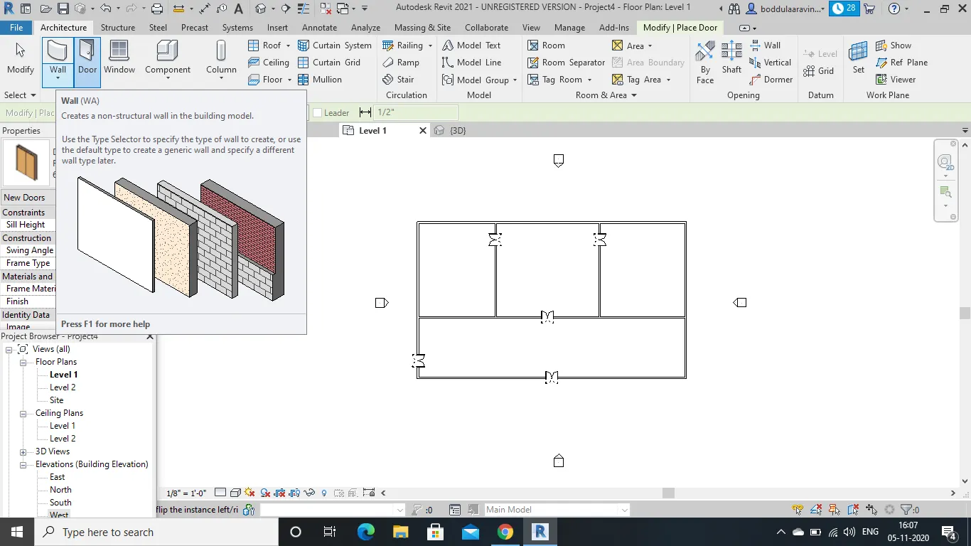
c)design the layout as you required.design doors to the designed layout.
d)now,select view toolbar and then select 3Dview to view the designed layout.
e)to get dimensions of the layout,go to Annotate tool and select Aligned icon to measure the dimensions.
f)you can now measure dimensions by clicking on two ends of the the wall.
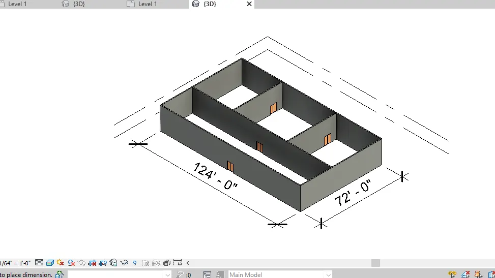
RESULT:We have created the layout of residential unit and 3d view has been shown and measured the layout using aligned option.
6th Answer:
AIM:to draft the levels of details including dimensions of room,components to add in residential unit.
TOOLS REQUIRED: elevations,3dview,annotate,linear.
PROCEDURE:
a)in the layout designed,to draft the levels,go to elevations in the properties.
b)select any one of the elevation(east,north,south,west) by double clicking.
c)after clicking,we can view the elevation side of the layout.we have to click on the wall and drag it to the required level and lock it.
d)similarly,repeat the same with all the other elevations.
NOTE:all the elevations should be of same height.
e)look at the 3dview,we can see the required length of walls.
f)to measure dimensions,go to Annotate tool and select linear when the view is in layout.
g)after selecting it,measure the dimensions by clicking on the end points of the required.we get dimensions of the required rooms.
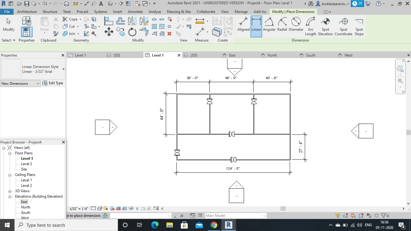
RESULT:drafting of levels including dimensions of room is done succesfully.
7th Answer:
AIM:To identify the residential model elements such as door,windows,tables,chair,couches,bed,lamps from library and insert to the model and saving the project.
TOOLS REQUIRED:Insert,contents,load family.
PROCEDURE:
a)at first,design a paln with walls and doors.
b)now,go to insert toolbar and click load family to load the libraries.
c)load all the required things like tables,chairs,beds,couch,lamps,doors,windows etc.
d)now click on component that is in the architecture and click on place a component.
e)loaded libraries are visible in the properties after clicking in the place a component option.
f)now load all the required contents and place in the required positions of the wall.
g)to save the project,go to file and click save as.we have project after clicking save as.click on it.
h)now you can save the file name and click on ok to save it.
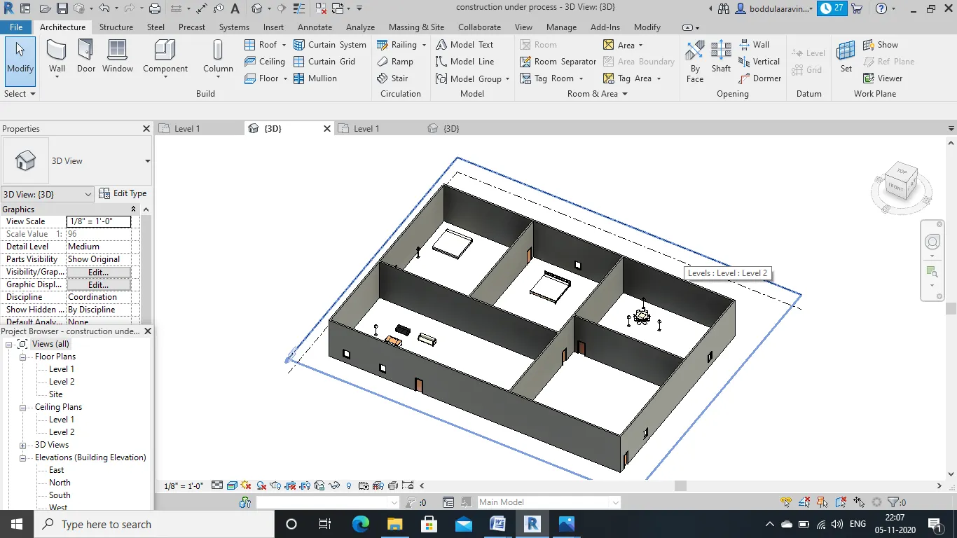
RESULT:identifying the residential model elements such as door,windows,tables,chair,couches,bed,lamps from library and inserting to the model and saving the project is accomplished succesfully.