Week 1 Challenge
1st Answer:
AIM:To create a revit file and naming a file
TOOLS REQUIRED:File menu,open
PROCEDURE:
a)open the REVIT app that you have installed.
b)we will get a page where we can see open,new in models and families.click on new option from models.
c)we can see template file where we should select required one(like architecture,structural and other metric ones).then select project in create option,then click OK.
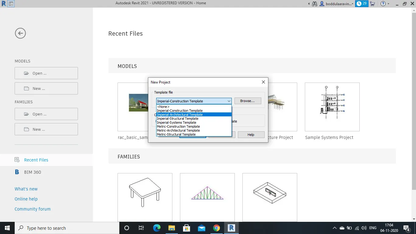
d)we will get the project main page where we can design and draft the projects.
e)To name the project,select MANAGE in the toolbar.
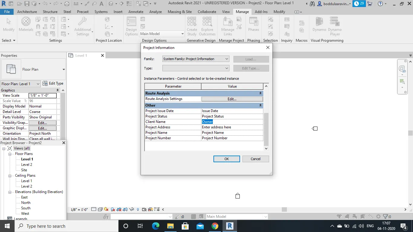
f)we can see all the shortkeys in manage toolbar.we have to select PROJECT INFORMATION to name the project.
RESULT:Finally we have created a new project and named the project.
2nd Answer:
AIM:To save the new project file,close and open using icons from file toolbar.
TOOLS REQUIRED:File,save as,naming file.
PROCEDURE:
SAVING FILE:
To save the file,we can proceed to following ways:
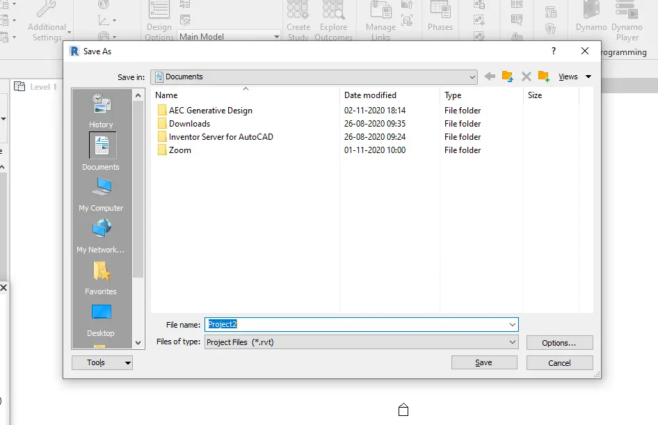
a)we can find the SAVE icon on top of the project page(menu bar).we can click there to save the file.
b)we can also see FILE tool in tool bar.when we click on it,we can find SAVE ption to save the file.
c)we can simply press ctrl+s to save the file.
OPENING AND CLOSING OF THE FILE:
a)select FILE tool in the toolbar.
b)we can find OPEN option click on open then search our saved file and click on it.
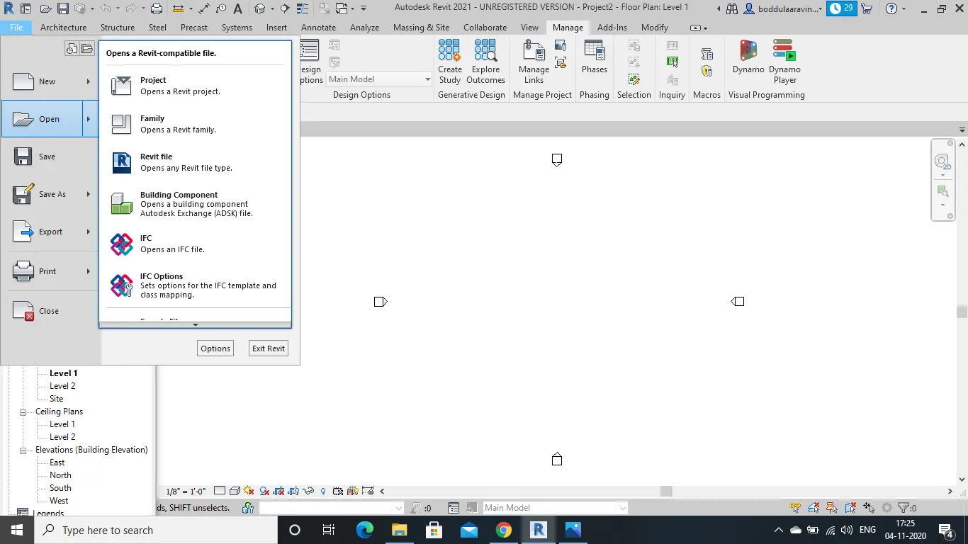
c)required file can be now opened .
d)we can also find CLOSE in the file tool.
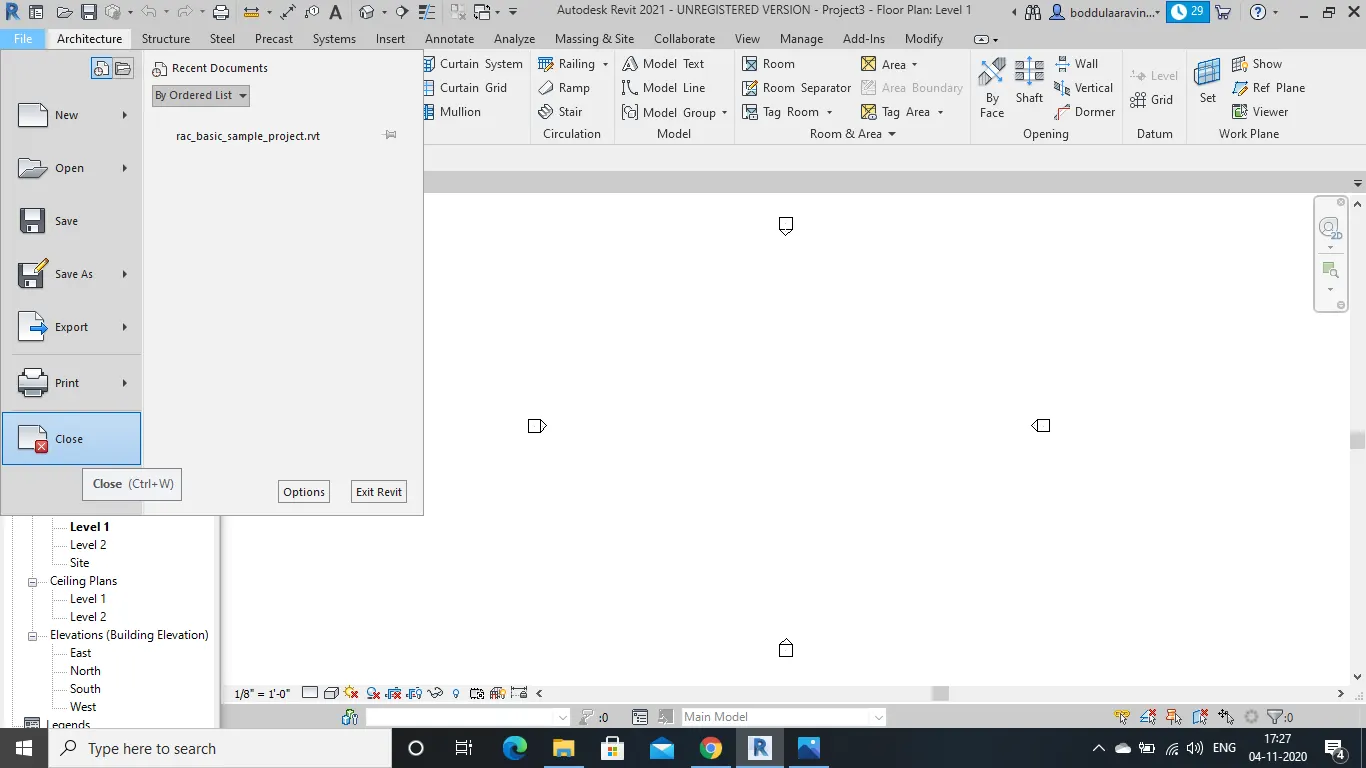
RESULT:the new project file has been opened and closed using icons from file toolbar.
3rd Answer:
AIM :To draw a wall from architectural/structural toolbar and to create a layout of wals of about 40'-0"x35'-0".
TOOLS REQUIRED :architecture,wall
PROCEDURE :
a)In case of architecture,when we select the architecture tool,we can get WALL icon.
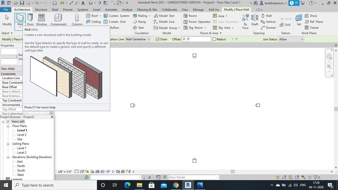
b)click on the wall icon which we are directed to modify tool.there we have the all the shapes in the most right corner,where we can select rectangle shape.
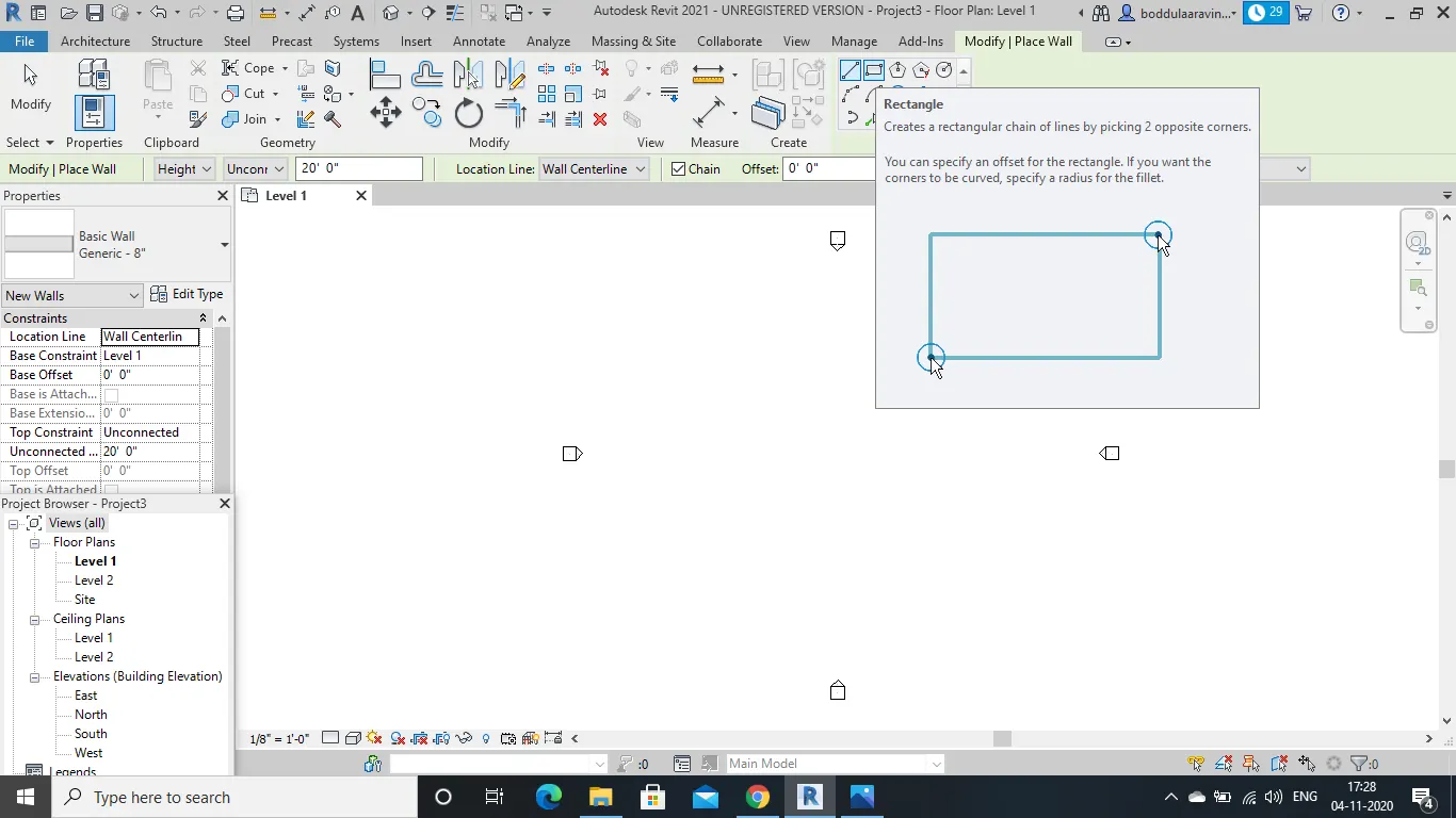
c)we are easily able to draw a rectangular wall of required dimensions.we can click on the x axis dimension and type 45' and do similar with y axis.
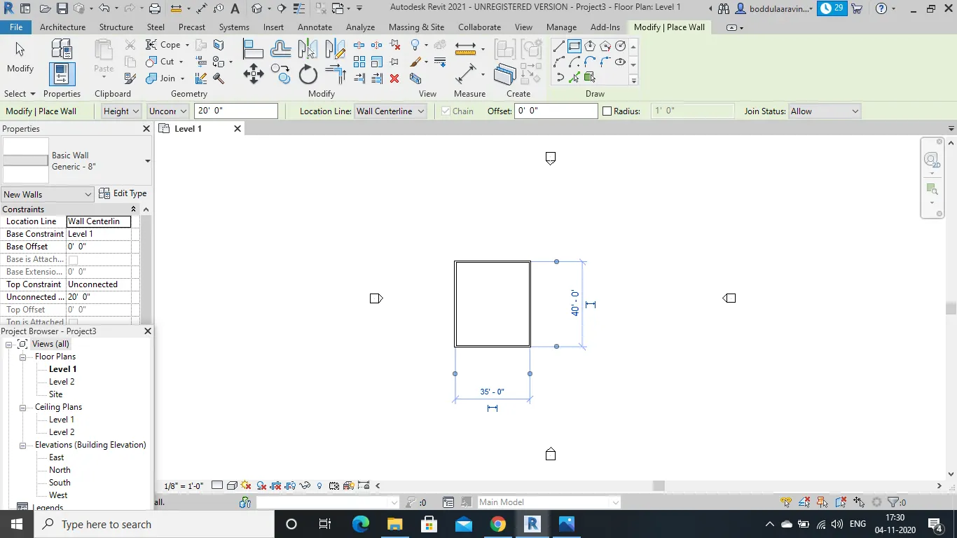
RESULT:The layout of walls of 40'-0"x35'-0" from architecture/structure toolbar is designed.
4th Answer:
AIM :To use aligned option to add dimensions to layout using annotate toolbar
TOOLS REQUIRED :Annotate,Alligned.
PROCEDURE :
a)draw an inclined wall.
b)now,go to annotate tool bar and press the aligned option in it.
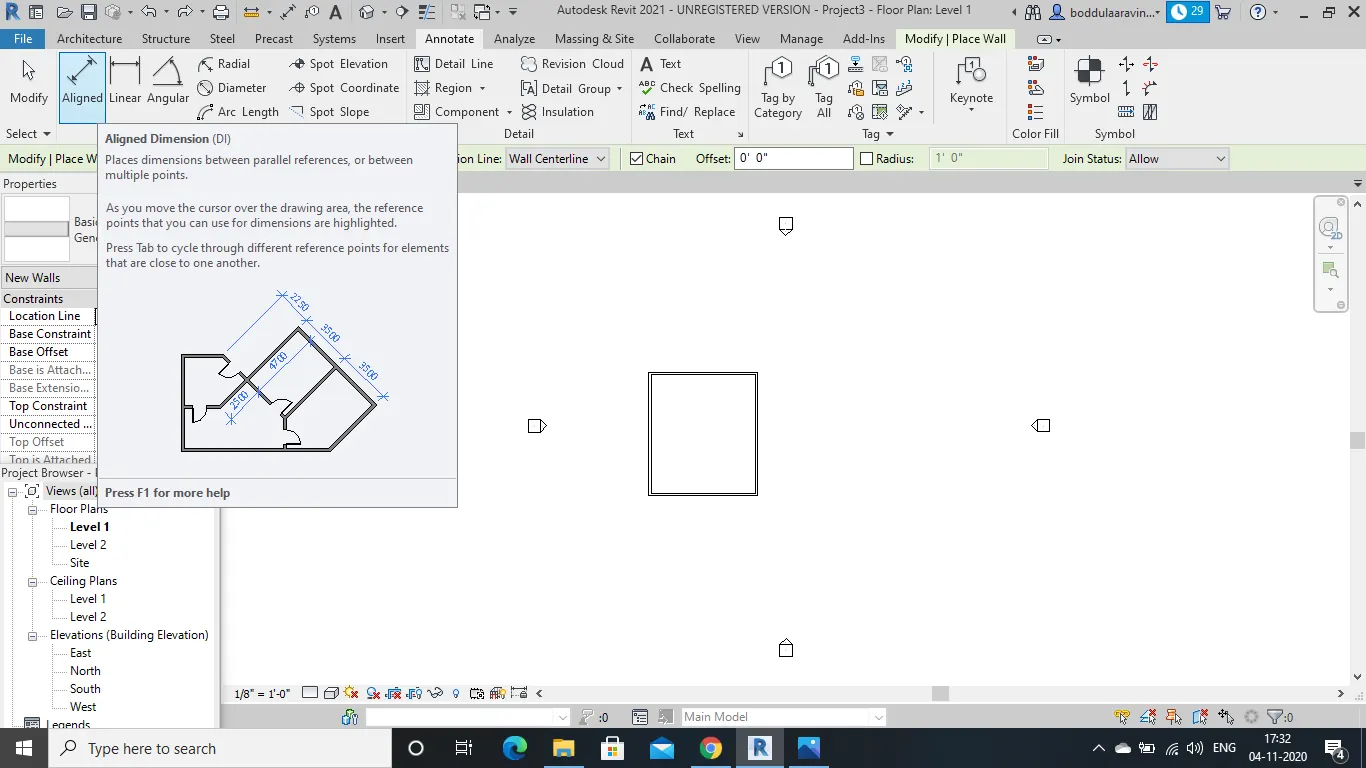
c)now,click on the first end and last end and drag it to some distance.
d)then,we can see the dimensons of the alligned wall.
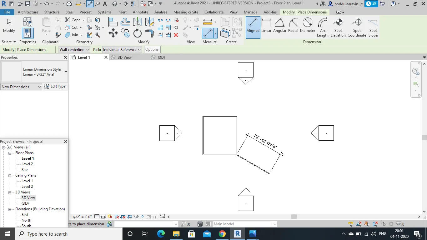
RESULT:Alligned option in annotate toolbar is used to add dimensions to the layout.
5th Answer:
AIM :To use the properties browser to switch to different wall types.
TOOLS REQUIRED :architecture,wall.
PROCEDURE :
a)first go to architecture tool and select the wall option in it.
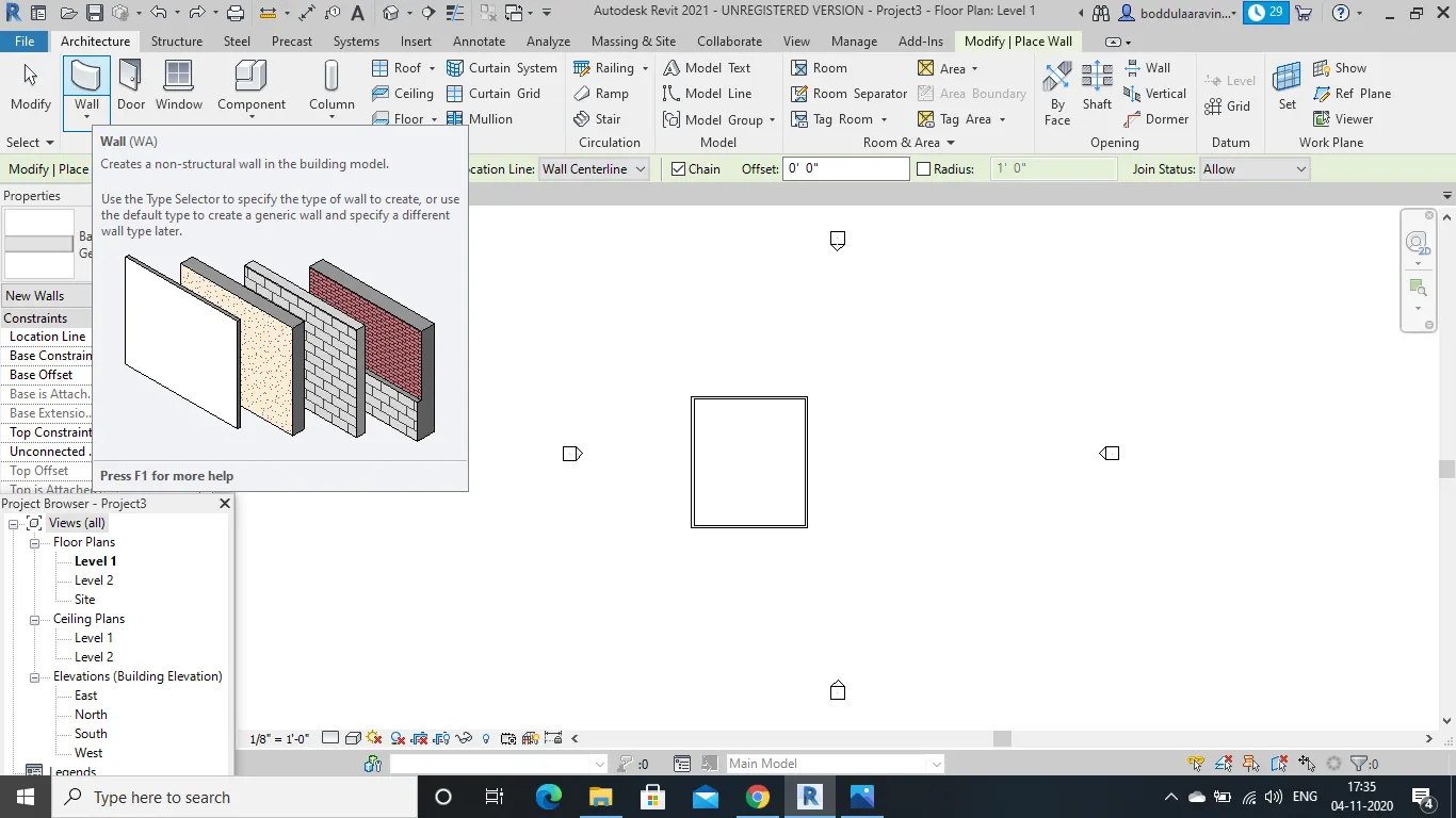
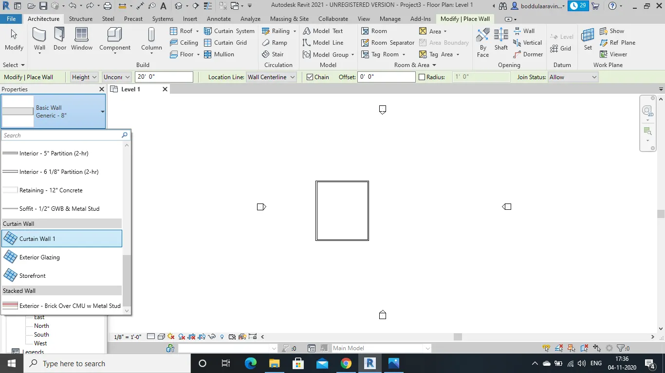
b)now we get properties in the leftside of the design,where we can see basic wall type.we have to select the small arrow which indicates options,click on that.
c)we are directed to different types of walls like curtain walls,stacked walls and also different generic dimensions of wall.
RESULT:Different wall types has been switched using properties browser.
6th Answer:
AIM :To create a 3d view with the toolbar and view the name appropriately.
TOOLS REQUIRED :view,3D,properties.
PROCEDURE :
a)after opening a new project,click on architecture tool to design a wall.
b)click on wall to design a wall.you will be directed to modify tool in which you can see the different shapes in which you can select rectangle or any other polygon.
c)draw a wall with a polygon.
d)click on view toobar to get 3D view icon.

e)now click on the 3dview .we get the 3d view there.
f)to make realistic,we can select visual style which is in the bottom and select realistic in it.
g)to change the 3d view name go to properties,where we can find identity data.
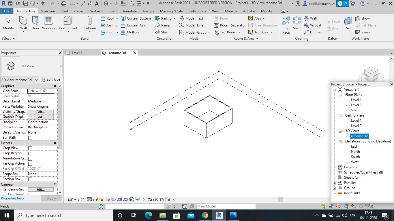
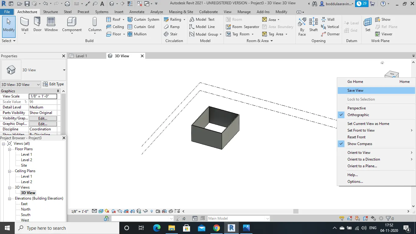
h)we have view name in it.double press on it to change the name.
RESULT :creating a 3d view and naming it is accomplished succesfully.
7th Answer:
AIM :To navigate through 3D model using view cube and orbit /pan through model layout created.
TOOLS REQUIRED :navigation wheel.
PROCEDURE :
a)create a 3D View.
b)after appearence of 3D view,we can find the front,back,right and left view on top right of the designing page.
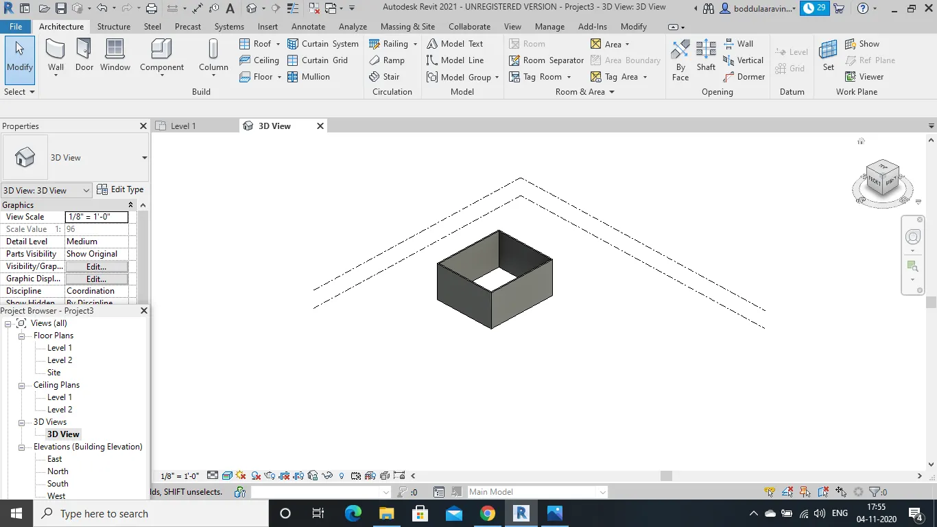
c)select on the required view,then we can see the views.
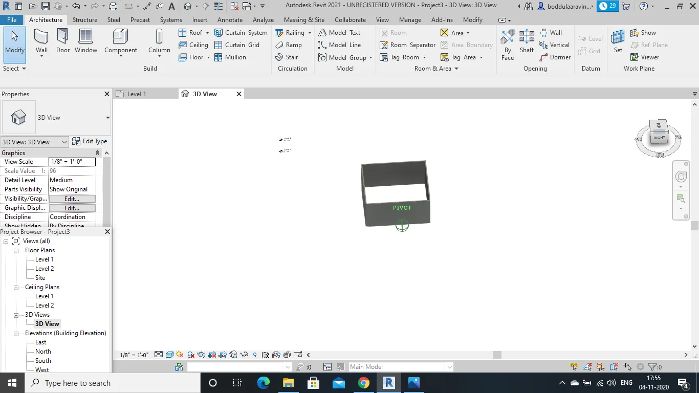
d)to change the pivot,we use orbit.and pan is the one in which we can change the respected view with the cursor by holding to pan.we can see pan and orbit in the rightmost of the page.
RESULT :navigating through 3d model using viewcube and orbit/pan through model layout is done succesfully.
8th Answer:
AIM :Using the visibillity setting below to switch model to shaded,realistic and hidden line options.
TOOLS REQUIRED :visual styles.
PROCEDURE :
a)create a 3d model
b)select visual style in the below toolbar.
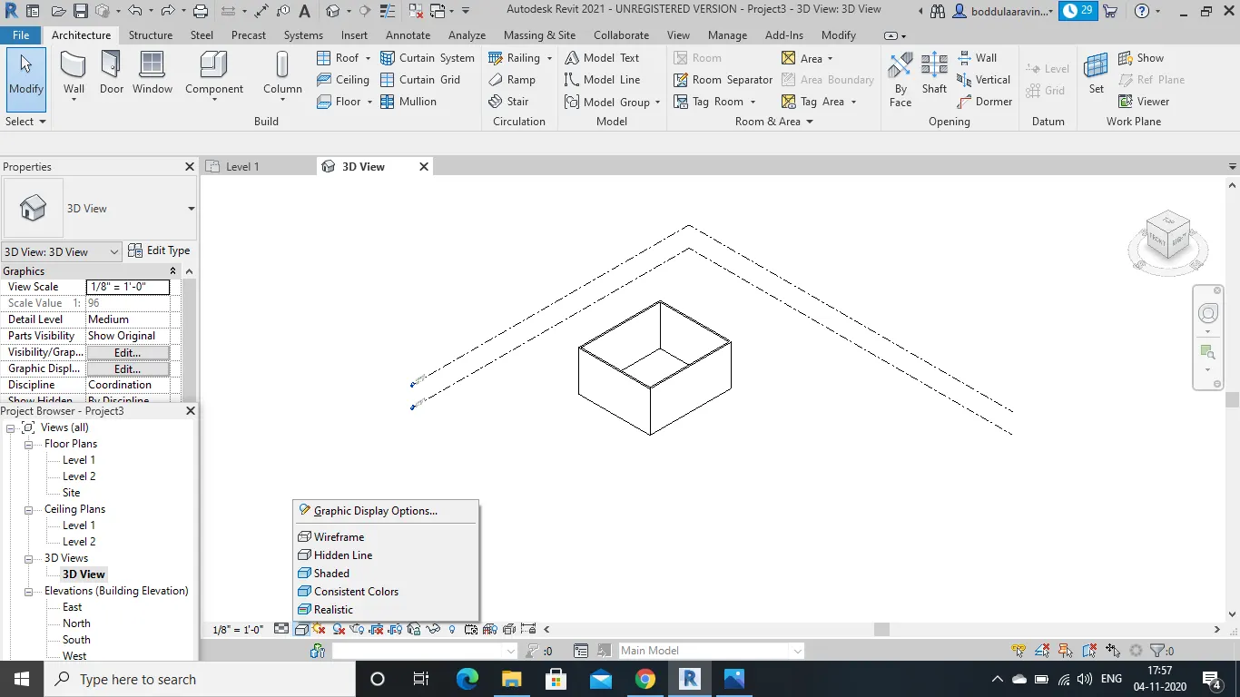
c)by selecting it,we will find graphic display options like realistic,wideframe,consistent colors ,shaded and hidden lines.
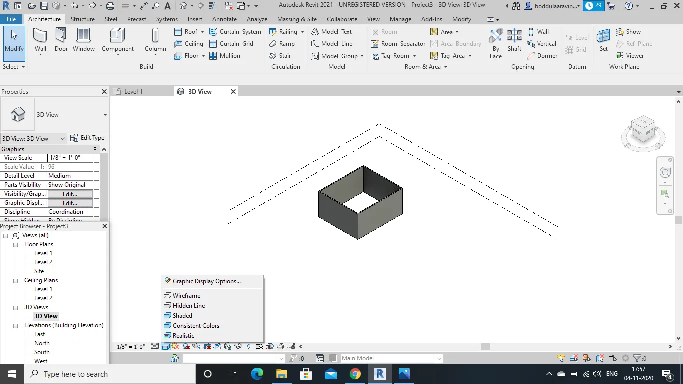
d)select the model that is required from the above.
RESULT :we can switch to different models by using graphic display option.
9th Answer:
AIM :To turn the sunlight on off to view shadings in the layout created.
TOOLS REQUIRED :sun settings.
PROCEDURE :
a)design a layout initially.
b)you can find the sunpath in the bottom toolbar.click on it.
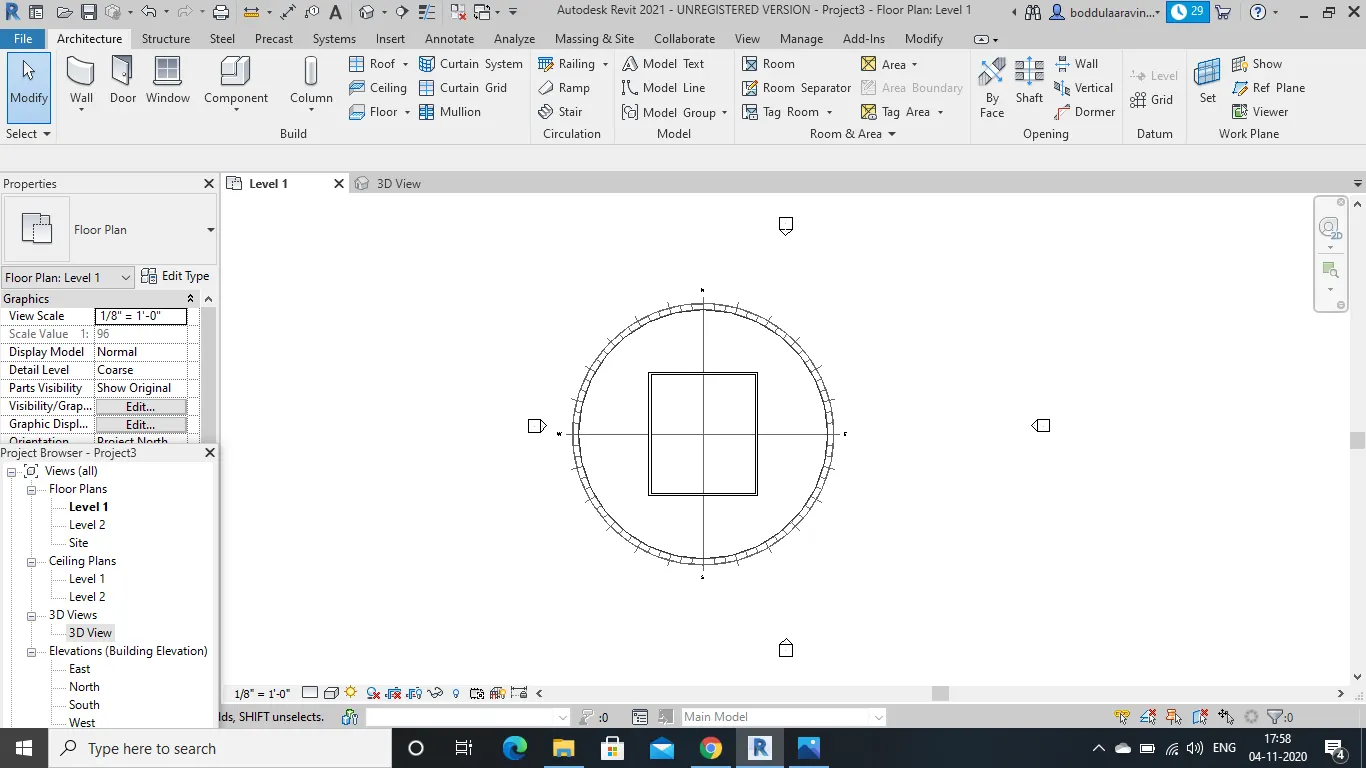
c)we can find options like sunpath on and off.we can select on and off there.
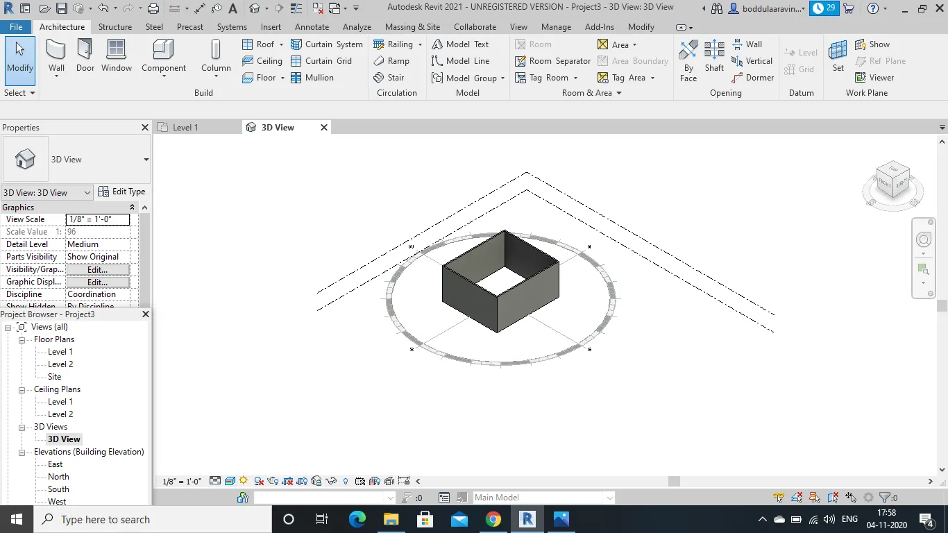
RESULT:using sun settings,we can switch to on and off sun shadings in the layout.
10th Answer:
AIM :To use the manage toolbar to enter the project settings,project name and project issue date.
TOOLS REQUIRED:manage,project information.
PROCEDURE :
a)after creating a new project ,to enter the project settings, use manage tool bar.
b)click on manage toolbar.
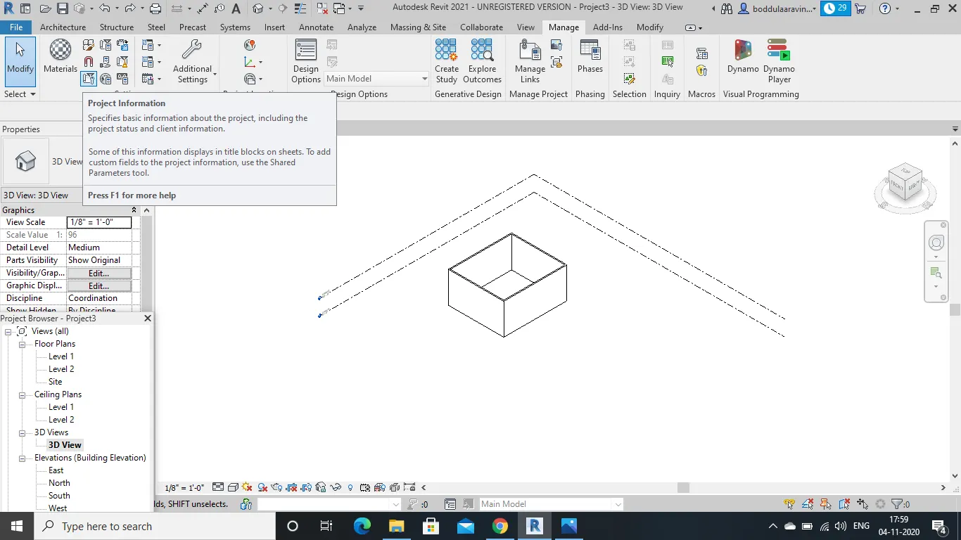
c)you can find project information(a small icon beside materials icon).click on it.
d)after clicking,instance parameters are visible to us.
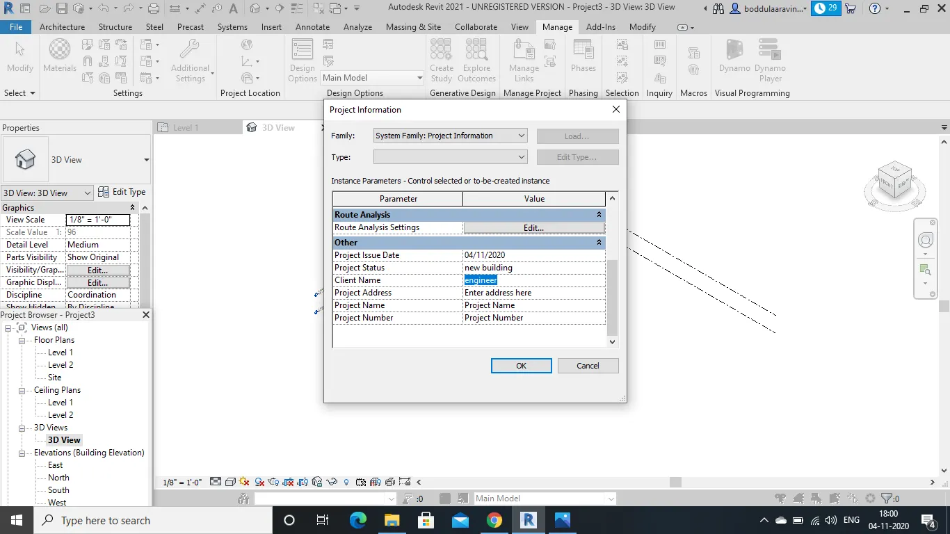
e)we have project issue date,project name and some other project settings in other instance parameters.
f)we can change and save our required information there.
RESULT :finally,we have entered the project settings,project name and project issue date.
11th Answer:
ANALYSE TOOLBAR is the tool which helps to combine the different loads in the structure,load combination etc.it is used to analyse the different loads that the structure can handle which gives analysis report as a result.It helps in detecting the load failure,load capacities in the structure.we have analytical models,spaces and zones,color fills and energy optimisations.

12th Answer:
links that support revit are LINK REVIT,LINK TOPOGRAPHY,LINK IFC,LINK CAD.

13th Answer:
collaborate tab in revit is used to collaborate more people to do the same project which results more efficiency and productivity as well as creativity.it is a cloud base service which allows any revit users to collaborate on doing the revit model.time is also reduced when more people work collaborately.
