Week 2 Challenge
1. 1. How will you assign the Circular section to a column?
ANSWER:
- Go to the properties panel.
- Click on the define option.
- Select the circular section from the list.
- Specify the desired diameter of the circular section.
- Click on add and a circular section of the specified diameter will be created.
- Now, select the section you just created and check the radio button that says assign selected to the view.
- Then, hit apply and ok and that's it. The circular section has just been assigned to your column.
2. How will you assign the Unit system to a .std model file?
ANSWER:
- Go to the File menu and click on the Settings option.
- A list of settings will appear, select the structure units from the same.
- Now, a dialogue box will show up where you can adjust the project units as required.
- So, change the units of dimensions, displacements, moments, etc.
3. What are the parameters to be specified while using the “Bay Frame” option?
ANSWER:
- Length
- Height
- Width
- No. of bays along length
- No. of bays along height
- No. of bays along width
4. Name a few codal standards incorporated in STAAD Pro software.
ANSWER:
- AISC 360-16
- AISI S100 2016
- ASCE 10 97
- ASME NF 3000 1974
- BS 5400
- CAN/CSA S136 64
- IS 800 - 2007
5. How will you specify the design compressive strength for an RCC section?
ANSWER:
- Go to the design panel.
- Click on the define parameters option.
- A list of design parameters shall appear.
- Look for the FC within the list which is nothing but the compressive strength of an RCC section (Fck).
- So, you can easily specify the compressive strength from here based on the grade of concrete adopted for the project.
2. 1. State the “Input” steps involved in RCC design.
ANSWER:
- Geometry
The geometry panel mainly controls the modeling part of a project. The entire building is drawn within the geometry input as per the Architectural layout received.
- Properties
Various section properties are assigned to the modeled beams, columns, and plates through properties input.
- Materials
Desired materials are assigned to the sections with the help of materials input.
- Specifications
Any special designations to be followed while analyzing are mentioned in this section.
- Supports
Base supports and the boundary conditions are defined through support input.
- Loading
Various loads are applied to the structure.
- Analysis
Computational analysis is executed based on the selected method in the software.
- Design
Finally, the building sections are designed and the area of reinforcements is extracted via design input.
2. Explain the difference between Fixed and Enforced support conditions in STAADPro.
ANSWER:
When enforced supports are defined, the software considers these as springs of high stiffness as opposed to fixed supports. It is only essential to define supports as enforced when you have FE models involving plates/solids and for which you need to impose support displacement loads
3. 1. Explain the steps involved in the analysis of a model using STAAD Pro sequentially.
ANSWER:
- Once the modeling has been completed and all the loads and combinations have been assigned to the building, the analysis part comes into play that is carried out systematically as mentioned below:
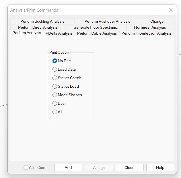
- Go to the analysis panel and click on the analysis commands option.
- A list containing various methods of structural analysis incorporated in staad will pop up.
- Select the method based on your project requirements.
- Click on the load list and make sure all the loads and combinations are selected to be run.
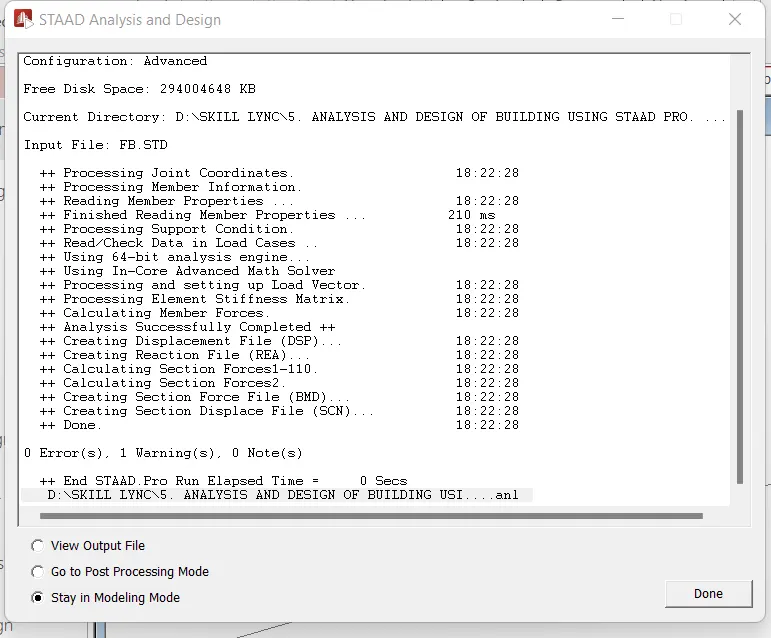
- Then go ahead and run the analysis by clicking on the run analysis option.
2. Explain the two ways in which a structural framework/model can be created in STAAD Pro software.
ANSWER:
- Node by Node
The first way is to model a building by adopting the node by node method. In this method, all the nodes of the structure as per the Architectural layout are placed manually by specifying the coordinates. The same nodes are then translationally repeated based on the building dimensions and levels.
- Structure Wizard
This is a more automated technique as compared to the node by node method. You can model any type of structure like truss, frame, and many more by adopting this method. There are further various methods within structure wizard using which the building can be modeled. For example, you execute modeling using the bay frame option in which you will be asked to specify the total length, width, and height of the building. Moreover, you will also input the no. of bays along each dimension as per the Architectural drawings received, and thus the modeling is completed.
3. Elaborate on the different support conditions in STAAD Pro.
ANSWER:
All the typical support conditions that we generally encounter are included in the software like fixed, pinned, spring, inclined, etc. Moreover, we can also create customized support conditions based on the project requirement with the use of fixed but support. In the fixed but support, we can release any degree of freedom as per the structural need.
4. How will you extract the stress distribution for a staircase slab?
ANSWER:
- After running the analysis successfully, go to the post-processing mode.
- Click on the view results option.
- There will be a drop-down list available within the plate results panel.
- From the same list, select the stress distribution result and hit ok.
- Now, staad pro will showcase the stress distribution divided into different color zones ranging from minimum to maximum stress values.
5. Explain the different ways to view SFD & BMD in STAAD Pro.
ANSWER:
- Go to post-processing mode after running the analysis successfully.
- Click on the beam results tab.
- A tool palette will appear within the beam results tab.
- Here, you can click on various values such as shear force and bending moments.
- To draw the diagram, click on Fy for the shear force diagram.
- Similarly, click on the Mz for attaining the bending moment diagram.
- Also, don't forget to check the annotate option to view values along with both the diagrams.
Practical
1. Analyze the following structural elements and validate the results
A. Simply Supported Beam
a. A Simply supported beam with two-point loads symmetrically placed
b. Span L = 20m
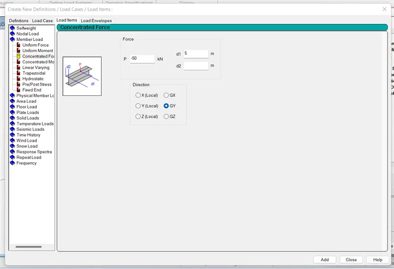
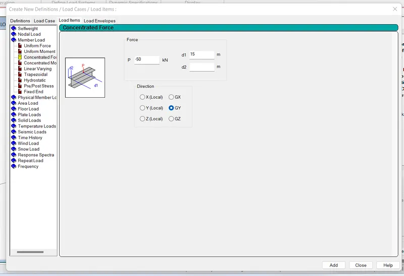
c. Load P = 50kN each
d. Both P located at 5m from each support
B.Fixed Beam
a. Span L = 16m
b. Uniformly Distributed Load w=9kN/m
ANSWER:
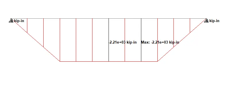
A. ANALYSIS OF A SIMPLY SUPPORTED BEAM
- Draw the beam of the required span which is 20m
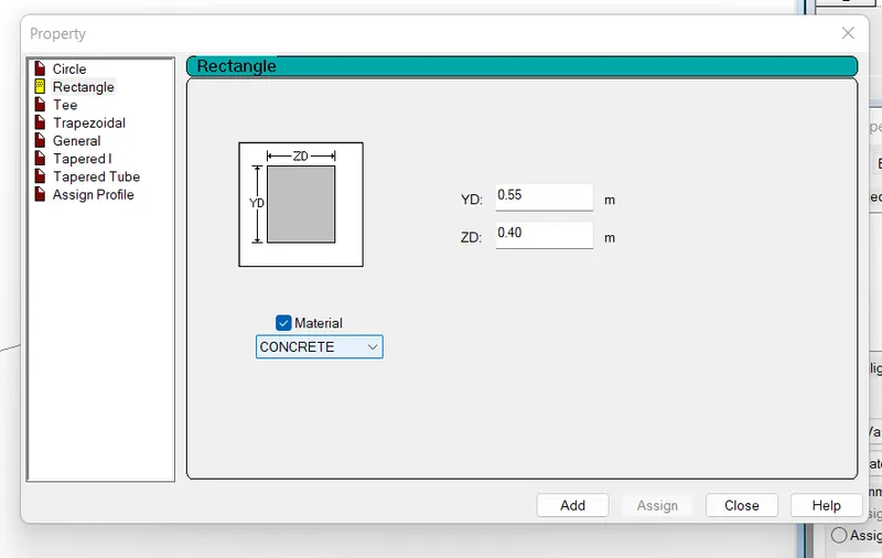
- Add a rectangular section of the typical beam dimensions
- Add the section and assign the same to the view
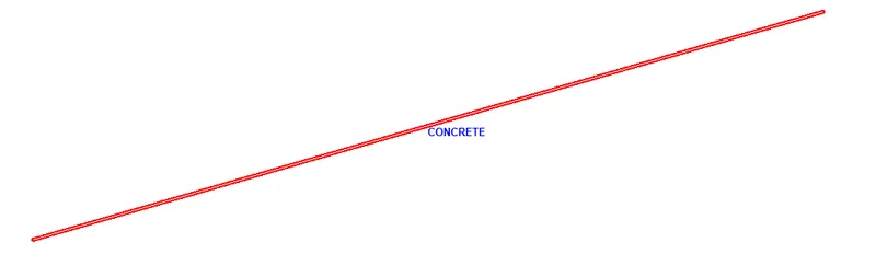
- Assign the beam material as concrete
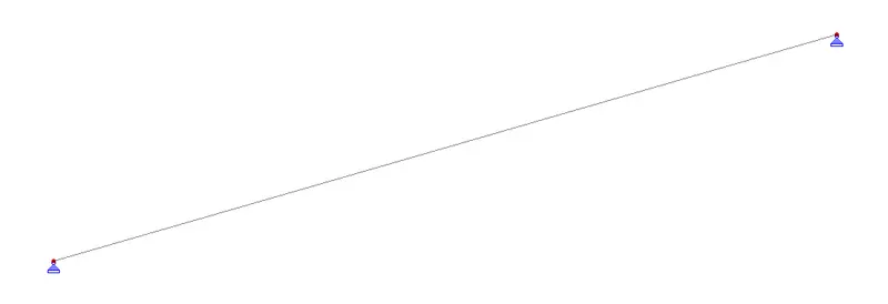
- Assign support conditions both ends pinned
- Assign two point loads of 50kn each at the specified distance
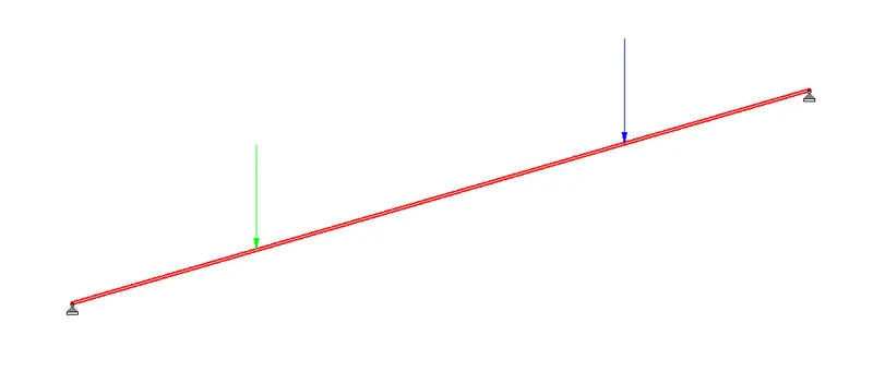
- Set the analysis method and run the analysis
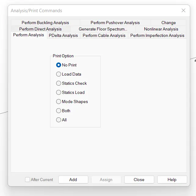
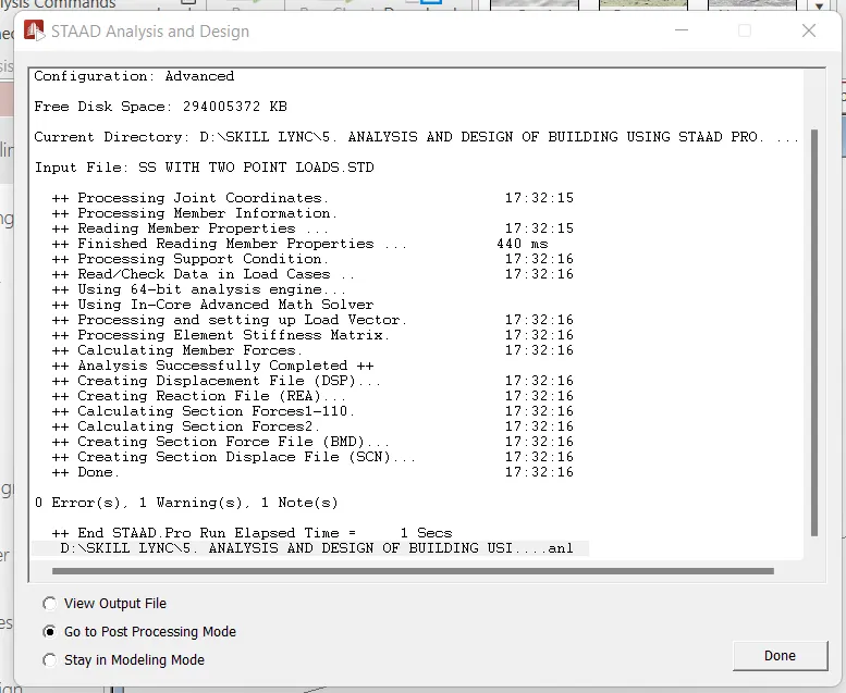
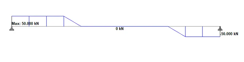
- Draw SFD and BMD
SFD
BMD
B. FIXED BEAM ANALYSIS
- Draw a beam of the required span which is 16m
- Assign a rectangular section to the same
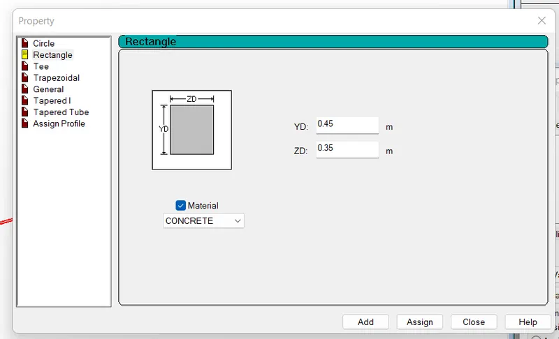
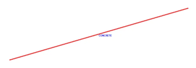
- Assign concrete material to the created beam section
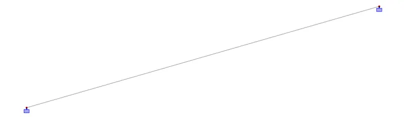
- Assign support conditions as fixed at both the ends
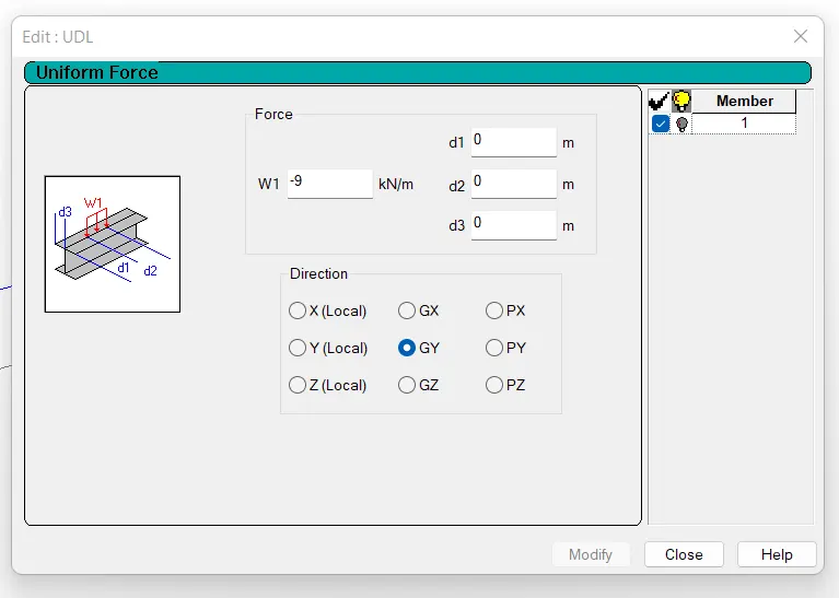
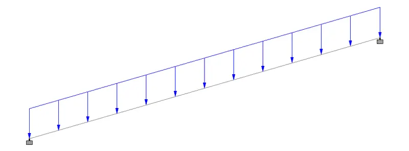
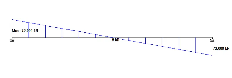
- Assign udl of 9kn/m to the entire beam
- Set the analysis mode and run the analysis
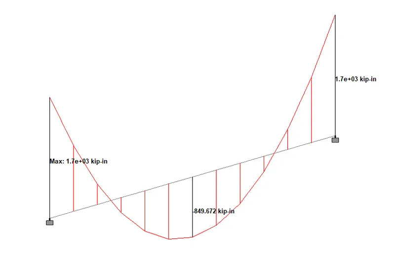
- Draw SFD and BMD
SFD
BMD