Creation of geometries by Coordinate system methods using AutoCad
AIM: TO CREATE DIFFERENT GEOMETRIES USING COORDINATE SYSTEMS IN AUTOCAD.
INTRODUCTION:
AutoCAD allows you to use two main coordinate systems to create the needed drawings at your ease. The names of the two coordinate systems are Absolute and relative coordinate systems. The relative coordinate system is further divided into two patterns namely relative rectangular and relative polar coordinate systems. The AutoCAD workspace consists of the X and Y coordinates same as a graph. And thus the coordinates are entered in accordance with the geometry of the figure to be provided. A detailed explanation for both of the systems using all techniques is discussed in this challenge.
PROCEDURE:
As directed in the question, figures P1 and P2 have to be created using all coordinate system methods. Hence the stepwise procedure for all the methods is explained to do so. But before getting into the drawing, let's quickly go over the fundamentals of coordinates and how to enter them while following all three of the methods.
1. ABSOLUTE COORDINATE METHOD (Drawing Fundamentals)
The absolute coordinate method as the name indicates is the procedure in which absolute or original coordinate values are entered. All drawing points are in reference to the origin of the cartesian graph and thus are entered as per their locations.
The coordinates of the drawing are entered in values of x's and y's in reference to the origin of the graph i.e 0,0. The coordinates are entered as x,y.
2. RELATIVE COORDINATE METHOD (Drawing Fundamentals)
Unlike the Absolute coordinate method, values of x's and y's are entered relative to the previous point of location within a drawing. And then how much do we need to move from the previous point is mentioned according to the next point location. There are further two subdivisions within the relative coordinate method being relative rectangular and relative polar coordinates.
- RELATIVE RECTANGULAR COORDINATES
In the relative rectangular method, coordinates are entered referring to the distance to be moved in the x and y-direction. and no need of mentioning the angle is required in this process. The format of entering the coordinates in AutoCAD is @x,y where x is the coordinates to be moved horizontally and y is the same to be moved vertically within the cartesian graph. Moving the right-hand side horizontally would be a positive x value while moving the left-hand side horizontally would be a negative x value. Accordingly moving vertically upwards would be a positive y value on the other hand moving vertically downwards would be a negative y.
- RELATIVE POLAR COORDINATES
While following the relative polar coordinate system, you need to enter the length to which you want to move and the angle at which your next point is located relative to your current position. The coordinates are entered as @length<angle. The angles are in reference to the quadrant system.
NOTE: THE FIRST POINT SHALL ALWAYS BE IN ABSOLUTE REFERENCE TO THE ORIGIN REGARDLESS OF THE METHOD BEING FOLLOWED.
Now, since we have understood the fundamentals of drawing using each system, let's go ahead and complete the geometrical figures given in the question.
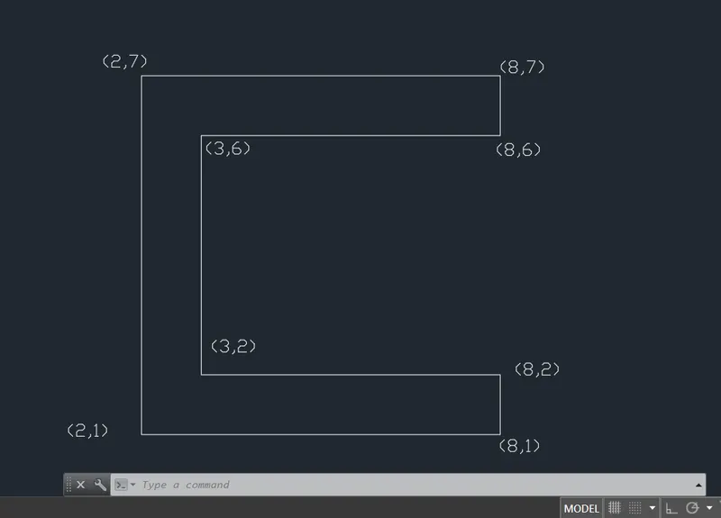
P1 (Absolute Coordinates)
- L -> Enter
- Specify the first point -> 2,1
- Start entering next points -> 2,7
- 8,7
- 8,6
- 3,6
- 3,2
- 8,2
- 8,1
- C -> ENTER (Close)
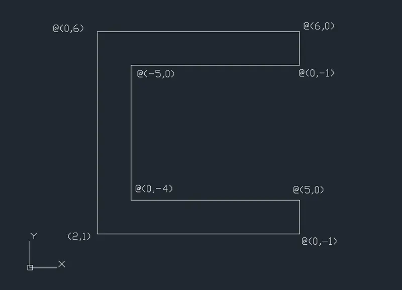
P1 (Relative Rectangular Coordinates)
- Specify the first point -> 2,1
- Start entering next points -> @0,6
- @6,0
- @0,-1
- @-5,0
- @0,-4
- @5,0
- @0,-1
- C -> ENTER (Close)
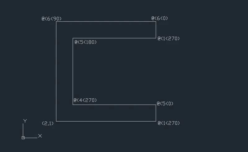
P1 (Relative Polar Coordinates)
- L-> ENTER
- Specify the first point -> 2,1
- Start entering next points -> @6<90
- @6<0
- @1<270
- @5<180
- @4<270
- @5<0
- @1<270
- C -> ENTER (Close)
P2 (Absolute coordinates)
- L -> ENTER
- Specify first point -> 2,1
- Start entering next points -> 4,8
- 7,8
- 9,1
- 6,1
- 6,5
- 5,5
- 5,1
- C -> ENTER (Close)
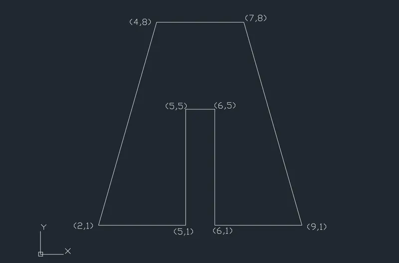
P2 (Relative Rectangular)
- Specify the first point -> 2,1
- Start specifying next points -> @2,7
- @3,0
- @2,-7
- @-3,0
- @0,4
- @-1,0
- @0,-4
- C -> ENTER (Close)
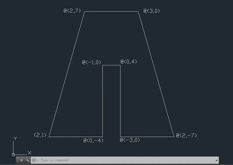
P3 (Relative polar coordinates)
- L -> ENTER
- Specify the first point -> 2,1
- Start specifying next points -> @7<74.05
- @3<0
- @7<285.95
- @4<90
- @1<180
- @4<270
- C -> ENTER (Close)
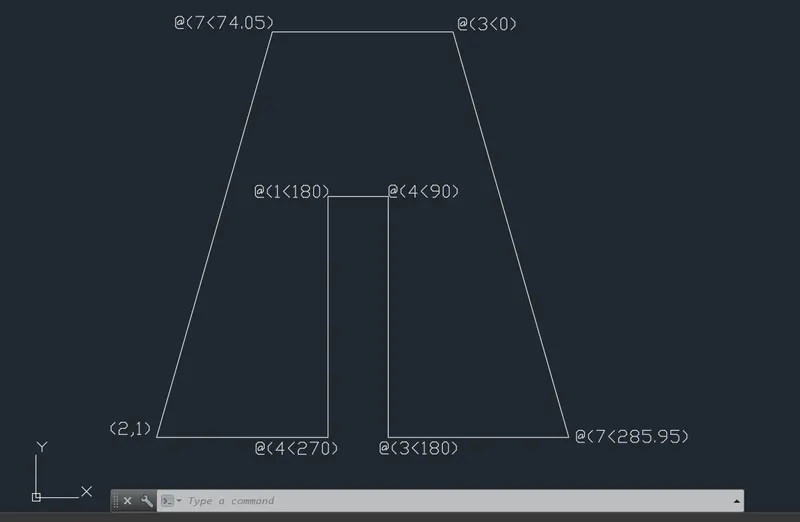
P3 (Relative Rectangular)
- L -> ENTER
- Specify the first point -> 2,1
- Start specifying next points -> @0,7
- @6,0
- @0,-1
- @-5,0
- @0,-3
- @3,0
- @0,-1
- @-3,0
- @0,-2
- C -> ENTER (Close)
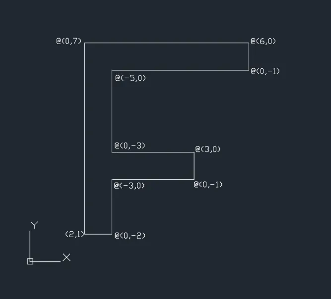
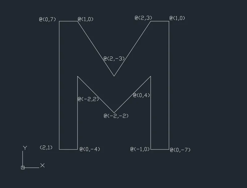
P4 (Relative Rectangular)
- L -> ENTER
- Specify the first point 2,1
- Start specifying next points -> @0,7
- @1,0
- @2,-3
- @2,3
- @1,0
- @0,-7
- @-1,0
- @0,4
- @-2,-2
- @-2,2
- @0,-4
- C -> ENTER (Close)
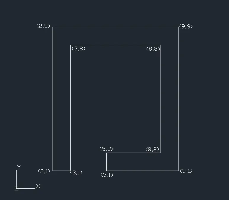
P5 (Absolute Cordinates)
- L -> ENTER
- Specify the first point 2,1
- Start specifying next points -> 2,9
- 9,9
- 9,1
- 5,1
- 5,2
- 8,2
- 8,8
- 3,8
- 3,1
- C -> ENTER (Close)
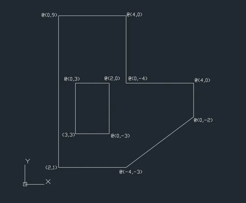
P6 (Relative rectangular)
- L -> ENTER
- Specify the first point -> 2,1
- Start specifying next points -> @0,9
- @4,0
- @0,-4
- @4,0
- @0,-2
- @-4,-3
- C -> ENTER
- L -> ENTER
- 3,3 -> The first point
- @0,3
- @2,0
- @0,-3
- C -> ENTER (Close)
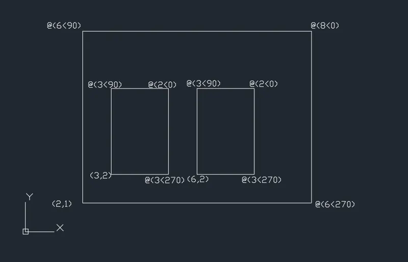
P7 (Relative Polar Coordinates)
- Specify the first point -> 2,1
- Start specifying next points -> @6<90
- @8<0
- @6<270
- C -> ENTER
- 3,2 -> The first point
- @3<90
- @2<0
- @3<270
- C -> ENTER
- L -> ENTER
- 6,2 -> The first point
- @3<90
- @2<0
- @3<270
- C -> ENTER (Close)
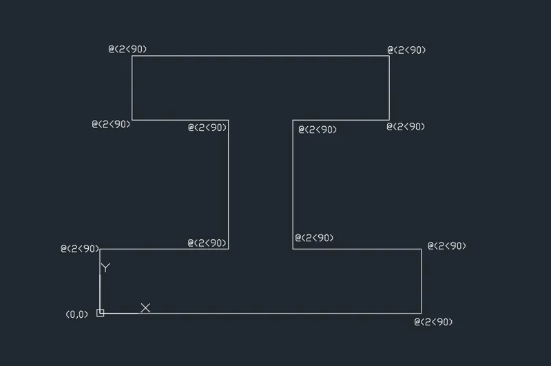
P8 (Relative Polar Coordinates)
- L -> ENTER
- Specify the first point -> 0,0
- Start specifying next points -> @2<90
- @4<0
- @4<90
- @3<180
- @2<90
- @8<0
- @2<270
- @3<180
- @4<270
- @4<0
- @2<270
P9 (Relative Rectangular)
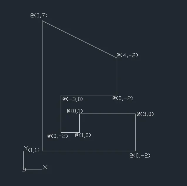
- L -> ENTER
- Specify the first point -> @0,7
- @4,-2
- @0,-2
- @-3,0
- @0,-2
- @1,0
- @0,1
- @3,0
- @0,-2
P10 (Relative Polar)
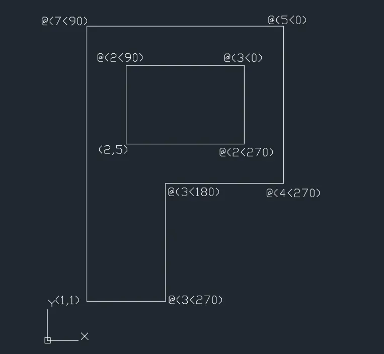
- L -> ENTER
- Specify the first point -> 1,1
- Start specifying next points -> @7<90
- @5<0
- @4<270
- @3<180
- @3<270
- C -> ENTER
- L -> ENTER
- 2,5 -> The first point
- @2<90
- 3<0
- @2<270
- C -> ENTER (Close)
Based on personal practice, the relative rectangular coordiantes system seems to be the most efficient one among all three. And hence, all the following civil figures are drawn using the Relative Rectangular coordinates system below:
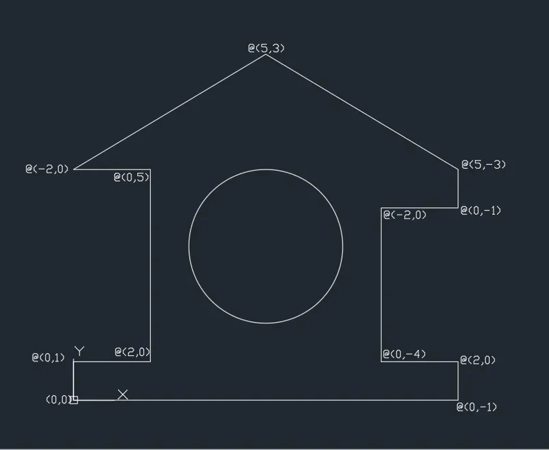
1. PROFILE WOOD
- L -> ENTER
- Specify the first point -> 0,0
- Start specifying next points -> @0,1
- @2,0
- @0,5
- @-2,0
- @5,3
- @5,-3
- @0,-1
- @-2,0
- @0,-4
- @2,0
- @0,-1
- C -> ENTER
- Go to Circle and select center-radius
- Specify Center -> 5,4
- Enter radius -> 2
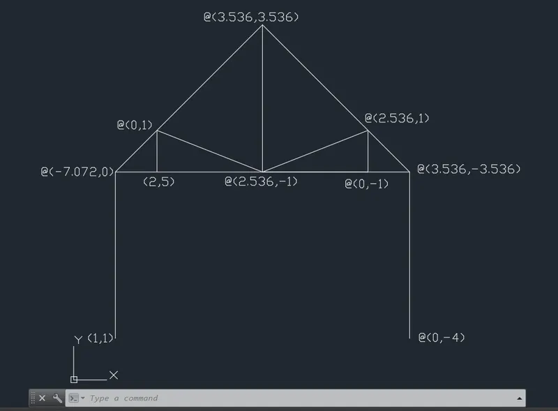
2. QUEEN POST TRUSS
- L -> ENTER
- Specify the first point -> 1,1
- @0,4
- @3.536,3.536
- @3.536,-3.536
- @0,-4
- @0,4
- @-7.072,0
- ESCAPE
- L -> ENTER
- 2,5 -> NEW STARTING POINT
- @0,1
- @-2.536,-1
- @2.536,1
- @0,3.536
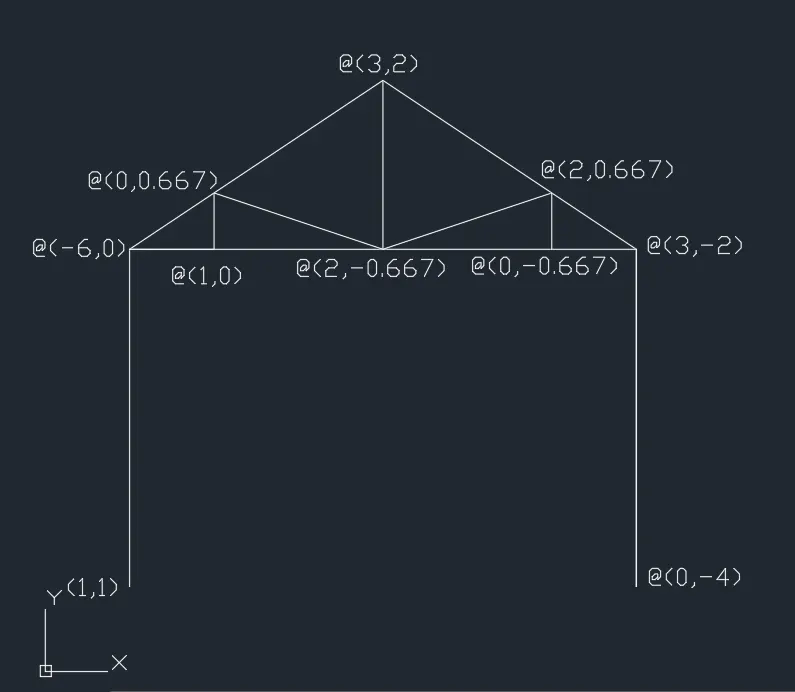
3. HOWE TRUSS
- L -> ENTER
- Specify the first point -> 1,1
- Start specifying next points -> @0,4
- @3,2
- @3,-2
- @0,-4
- @0,4
- @-6,0
- @1,0
- @0,0.667
- @2,-0.667
- @0,-0.667
- ESCAPE
- L -> ENTER
- 4,5 -> NEW STARTING POINT
- @0,2
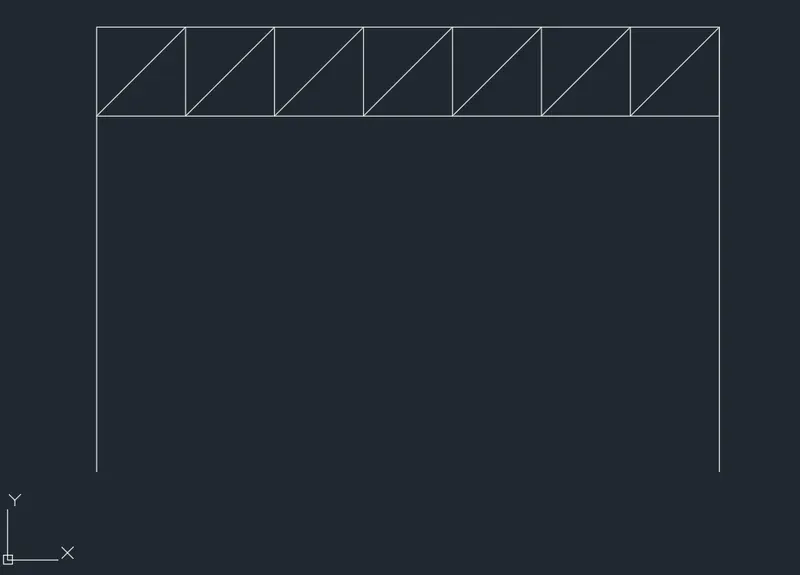
4. FLAT TRUSS
- L -> ENTER
- Specify the first point -> 1,1
- Start specifying next points -> @0,4
- @7,0
- @0,1
- @-1,1
- @0,1
- @-1,-1
- @0,1
- @-1,1
- @0,1
- @-1,-1
- @0,1
- @-1,-1
- @0,1
- @-1,-1
- @0,1
- @-1,-1
- @0,1
- @7,0
- @0,-5
5. MONO PITCHED ROOF
- L -> ENTER
- Specify the first point -> 1,1
- Start specifying next points -> @6,2
- @0,-2
- @-6,0
- @2,0
- @0,0.667
- @2,-0.667
- @0,1.333
- @2,-1.333