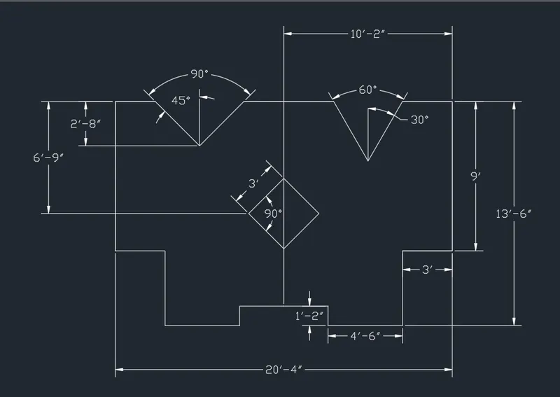
Drafting of various geometries using Chamfer, Fillet tool in AutoCad
AIM: To Create Different Constructional Geometries Using Chamfer, Fillet, and other Relative Commands in Autocad.
INTRODUCTION: Chamfer and Fillet are two of the often-used commands used while carrying out civil drafting works. Hence, it is important to know how and when to use these commands as per the requirements of the drawings. The primary function of Fillet is to connect two lines, points, or objects in a certain way in accordance with the structural requirements. You can connect the proposed lines in the form of corners, and also arcs with a certain radius. While Chamfer allows you to deduct the required distance and then connect two points according to the drawing given. So, many other commands in addition to Fillet and Chamfer are used in this challenge to complete the drawings as per the dimensions given in the question.
PROCEDURE:
Figure one:
- Setup the AutoCAD primary units as decimals as mentioned in the question.
- Invoke the line command by L-> enter
- Use the direct line creation method for straight and direct lines and enter the dimensions given in the question.
- Calculate line angles from the data given in the question.
- Use the relative polar line creation method and give accordant distances and angles that have been calculated.
- Locate the centers of the circles using construction lines.
- Create circles according to the diameters given in the question from the respectively located centers.
- Finish the drawing by running the dimensions and matching them with the one given in the challenge.
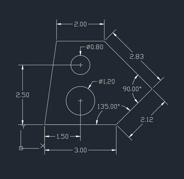
Figure Two:
- Setup the AutoCAD primary units as Architectural as mentioned in the question.
- Invoke the line command by L-> enter
- Use the direct line creation method for straight and direct lines and enter the dimensions given in the question.
- Calculate line angles from the data given in the question.
- Use the relative polar line creation method and give accordant distances and angles that have been calculated.
- Finish the drawing by running the dimensions and matching them with the one given in the challenge.
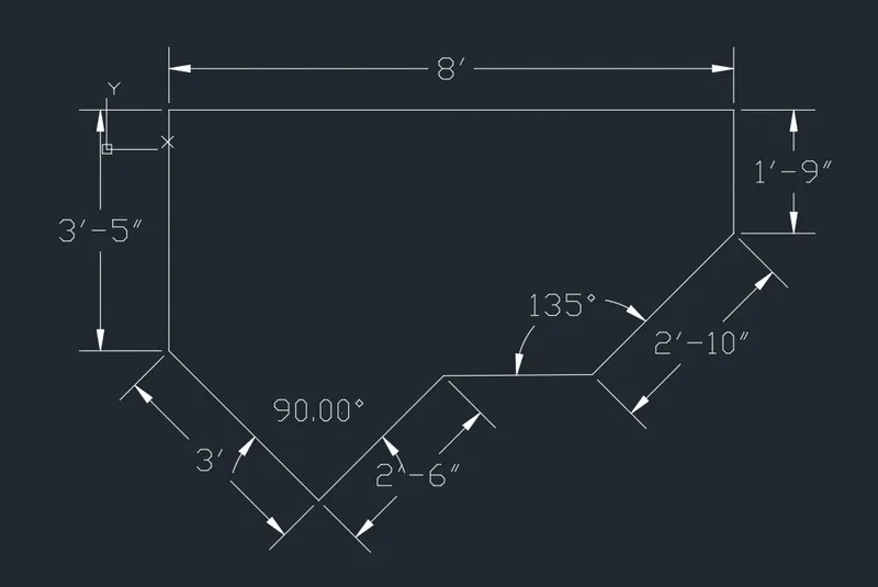
Figure Three:
- Setup the AutoCAD primary units as Engineering as mentioned in the question.
- Invoke the line command by L-> enter
- Use the direct line creation method for straight and direct lines and enter the dimensions given in the question.
- Calculate line angles from the data given in the question.
- Use the relative polar line creation method and give accordant distances and angles that have been calculated.
- Locate the center of the circle using construction lines.
- Create the circle according to the diameter given in the question from the respective located center.
- Finish the drawing by running the dimensions and matching them with the one given in the challenge.
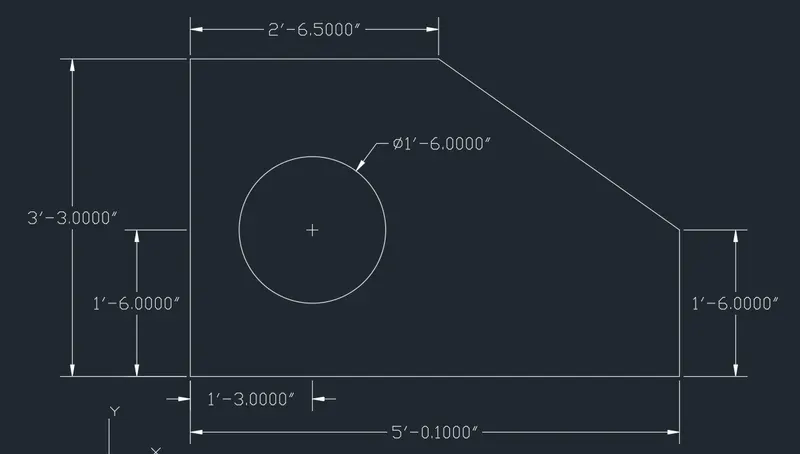
Figure Four:
- Setup the AutoCAD in the typical Imperial units.
- Invoke the line command by L-> enter
- Use the direct line creation method for straight and direct lines and enter the dimensions given in the question.
- Finish the drawing by running the dimensions and matching them with the one given in the challenge.
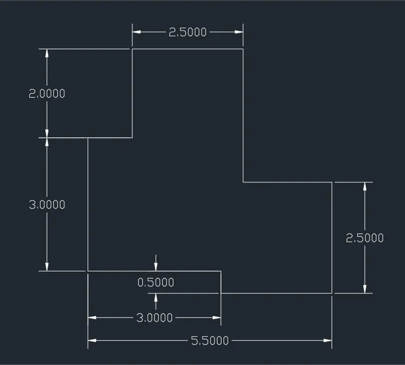
Figure Five:
- Setup the AutoCAD in the typical Imperial units.
- Invoke the line command by L-> enter
- Use the direct line creation method for straight and direct lines and enter the dimensions given in the question.
- Locate the centers for circles using the construction lines.
- Draw circles according to the diameters given in the question.
- Finish the drawing by running the dimensions and matching them with the one given in the challenge.
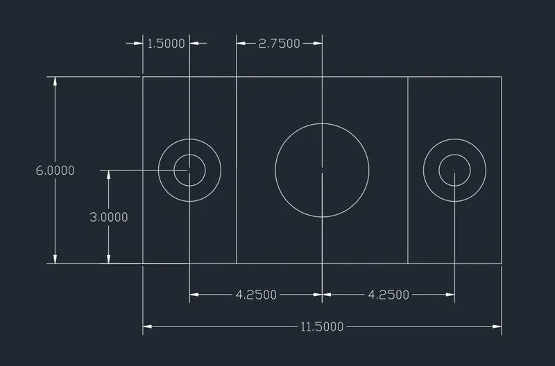
Figure Six:
- Setup the AutoCAD in the typical Imperial units.
- Invoke the line command by L-> enter
- Use the direct line creation method for straight and direct lines and enter the dimensions given in the question.
- Finish the drawing by running the dimensions and matching them with the one given in the challenge.
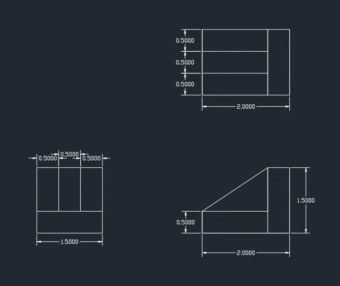
Figure Seven:
- Setup the AutoCAD in the typical Imperial units.
- Invoke the line command by L-> enter
- Use the direct line creation method for straight and direct lines and enter the dimensions given in the question.
- Locate the centers for circles using the construction lines.
- Draw circles according to the diameters given in the question.
- Use Fillet command with radius as specified in the question.
- Join the remaining lines with Fillet and the radius as mentioned in the question.
- Finish the drawing by running the dimensions and matching them with the one given in the challenge.
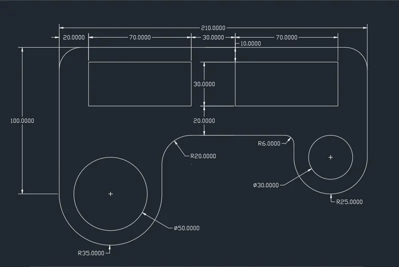
Figure Eight:
- Draw two circles with the same center and the diameters as 4 and 5 units.
- Locate the center points of the remaining two circles using construction lines.
- Draw the circles with 0.9 units diameters.
- Draw tangent lines to the bigger circle.
- Use the Fillet command with a radius of 0.9 and join the tangent lines as indicated in the question.
- Finish the drawing by running the dimensions and matching them with the one given in the challenge.
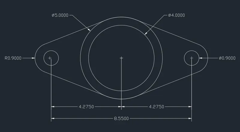
Figure Nine:
- Draw two circles at a distance of 32 feet and 6 inches with the radiuses as 8 and 9 respectively.
- Select the Start, End, Radius option from the Arc command.
- Give starting and endpoints with the radius as given in the question and join the line created in the beginning.
- Trim all the unnecessary elements and complete the drawing.
- Finish the drawing by running the dimensions and matching them with the one given in the questions.
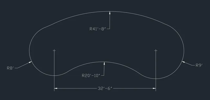
Figure Ten:
- Draw two rectangles with a difference of one unit in length and width one above the other.
- Copy both of the rectangles to a different workable place.
- Rotate them to an angle of 45 degrees.
- Move the rotated rectangles from their centroid and paste it precisely matching the center point of previously created straight rectangles.
- Do the trimming as per the detailings given in the question.
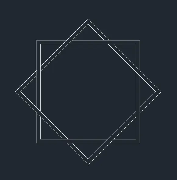
Figure Eleven:
- Setup the AutoCAD primary units as a typical decimal workspace.
- Invoke the line command by L-> enter
- Use the direct line creation method for straight and direct lines and enter the dimensions given in the question.
- Calculate line angles from the data given in the question.
- Use construction lines and locate all the points in the figure according to the conditions given in the question.
- Use the relative polar line creation method and give accordant distances and angles that have been calculated.
- Finish the drawing by running the dimensions and matching them with the one given in the challenge.