Week 2:- BiW Fixture Basics Challenge
1. PROCESS OF PROJECT EXECUTION ACTIVITY.
PROJECT ACTIVITIES STEPS.
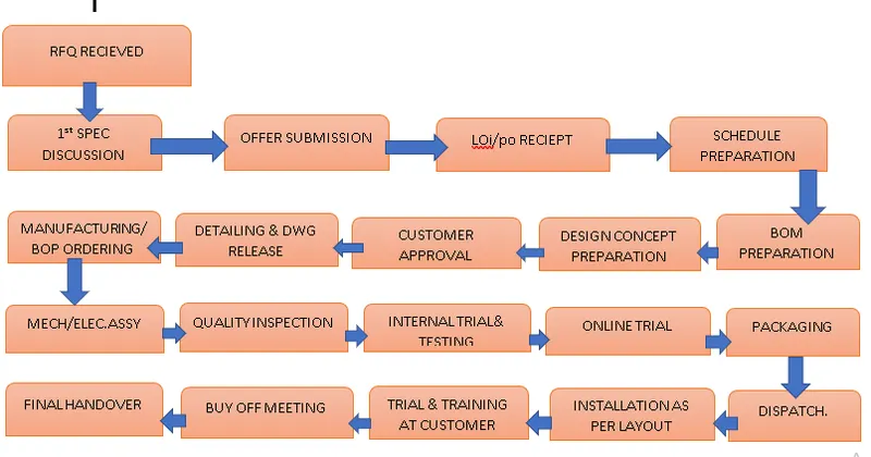
EACH STAGE AS THEIR OWN SPECIFIC WORK. AS EXPLAINED BELOW.
- RFQ RECIEVED.
request for quatation recieves from the industry. this RFQ is that which explains the customer needs in the way of doctumentation .customer tells what is needs like specifications, dimensions quality ,aterial,& all data is explained in detain in that. & gives to the company so that the company has the next step called as 1st spec discussion.
- 1st SPEC DISCUSSION & OFFER SUBMISSION-
in this stage the recieved doct from the customer is studies & knows what the company expecting from us & discuss with the team & prepares the times requirement, cost, material, labour, etc & re submeet the doct preparing the table so that the customer should satisfy the company time line & process . in the same way the customer sends the doct to some companies & he recieves the doct & the customer studies & compares the doct & selects which is familier to him & gives the offer to that specified company to start the work process.
- LOI/PO RECIEPT-
po means project offer recieved from the customer to manufacture the project required to him.to do some work or a project their shoul some time management so that the company prepares the time table schedule . so that the work process will go good. as explained below.this project sheet has every information regarding time required material, labour required, design concept till the product is hand over to the customer.
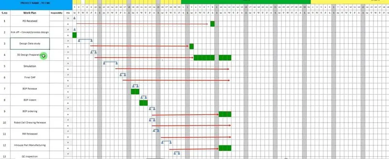
this time table is followed by every worker who are specilized to do this project.from starting till end every process is mentioned in this table. this table is prepared before starting the project.
- BOM PREPARATION- In this stage calculates what are the parts ,materials , etc re required to complete the project are assumed then go with the next step
- DESIGN CONCEPT PREPERATION - In this step the concept sketch is prepared by yhe design engineers with following requirements needed to the customer with exact accuracy.then sents to the customer
- CUSTOMER - Here the customer verifyes the design specifications recieved from the company & simulates the design so that all the positions dimensions etc are considred in desired condition or not if ok then submeets to the company to continue their process this is called customer approval.(DAP) design approval process. is there any change to be done in the design will be informed to the company & the changes to be done & again conforms with the customer.
- DETAILING & DRAWING RELEASE - In this stage the designed drawing is releaed to manufacture .
- MANUFACTURING/BOP ODERING- After recieving the drawing from the drawing team then starts the odering of required materials needed to start the work like cylinders ,rizers,mylors,specification sensors etc. once recieved all the manufacturing items inspection is done with the quality isnpection team that all the recieved items are related to the drawing or not & conforms it.
- MECHANICAL & ELECTRICAL SAAEMBLY - All the recieved materials are assembled as per the design requirement . to form a structure.
- QUALITY INSPECTION Here the assembled part is inspected with this quality inspection team weather all the sensons parts etc are in correct position or not. as per the design dimensions positions & also cmm coordinate measuring machine is tested weater all the pins are in the equal dimensions are not & ask for approval.
- INTERNAL TRAIL & TESTING- In internal trial & testing checks all the welding positions hole position are in specified path or not. if not do that corrections.because all the work is done by manual there will be some mistakes will happen to avoid that this internal trail & testing is done.
- ONLINE TRIAL- In this stage all the testing is done in automatic mode with control panel every thing should be worked with electrical connections as per the sequence & process. then approved through the online trail then goes to the packaging.
- PACKAGING DISPATCH. - The manufactured assembly is packed in such a way that it should withstand all the damages or some miss handling errors while transporting.
- INSTALLATION AS PER LAYOUT- the layout is done to install the fixture position robot position & where the fixture is attached to the robot chekcs all the reqirements & installs it.
- TRIALS & TRAINING AT CUSTOMER- Here the production trials,online trials is done . weather the required target is gaining or not in the scheduled shift & the desigred accuracy of the production material is obtaining or not all the specification are considred here. if it conforms the training is given to the staff members & engineers to operate the equipment .process & sequence of working.
- BUY OFF MEETING- Here the customer advises the company weather more soecification to me added to it . any missing parts in designing & raises the modifications accordingly
- FINAL HAND OVER-This is the completion of the project handover the product to the customer.
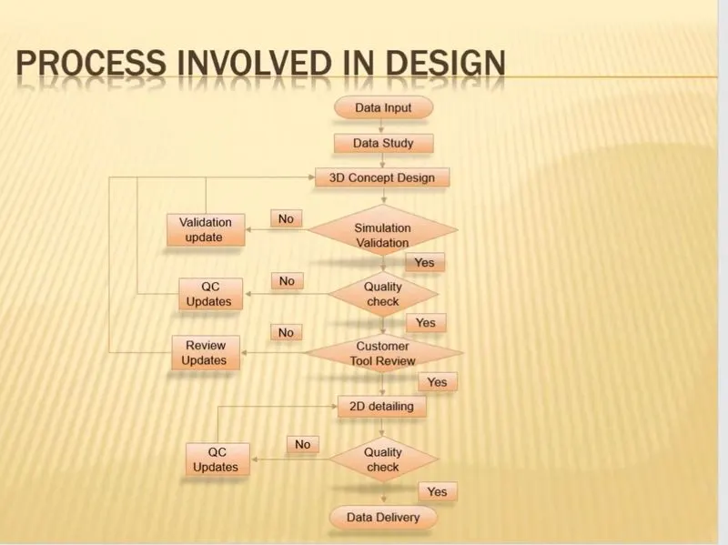
to design the model the following steps were followed.
the design to done in such a way that should follw the design consideration given by the data input with out any irregularities & that designed data is sent to the simulations validation team ,quality checking team here the designed data is simulated & verifies the data to be accurate & updates it.where the welding is to be done etc.according with the robot considerations. then sents to the customer review to conform with them to be proceed with the 2d detailing team for quality check & the data is delivered.
2. TYPES OF JOINING PROCESSES-
In car body constructions, mechanical joining procedures are used to join components of differing materials. This applies to many connections with (and between) steel, aluminum, and fiber composites. Simufact supports simulation of these processes, including self-piercing riveting (SPR), blind riveting, flow-hole screwing and clinching.
DIFFERENT JOINING PROCESSES
- Welding
- Brazing
- Soldering
- Bonding
- Nailing
- Screwing
- Bolting
- Riveting
- Clinching
- Stapling
- Press fitting
Joining processes include welding,brazing,soldering,mechanical fastenings,& adhesive bonding.mechanical fastening can be used to provide either temporary or permanent joints while adhesive bonding welding brazing & soldering processes are mainly used to provide permanenet joints
some of them are explained below:
MECHANICAL FASTEING
- The joining of material combinations which cannot be easily welded such as pre-painted steels or very dissimilar metals.
- Ex: Al applications in auto body make use of mechanical fastening techniques to overcome the poor inherent weld ability of Al.
- The joining of materials in application where high fatigue life is critical compared to strength.
- The joining of materials where a long tool life is of relatives importance.
- Screws & tools.
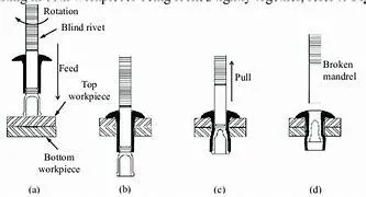
SELF PIERCING REVETING.
- Self-piercing riveting is a high -speed mechanical fastening process for the point joining sheet material typically steels & aluminium alloys.it is a single-step techinque generally using a semi-tabular rivet to clinch the sheets ina amechanical joint.
- atahere is also a process varient which utilise solid rivets.
- As the name suggets ,pre-drilled holes are not required,allowing the joint to be made rapidly in one operation. the process cycle is shown in cross-section below.
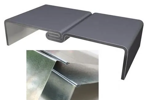
HEMMING PROCESS
Hemming and seaming are two similar metalworking processes in which a sheet metal edge is rolled over onto itself. Hemming is the process in which the edge is rolled flush to itself, while a seam joins the edges of two materials
ADHESIVE BONDING
Adhesive bonding is a type of permanent joint used in sheet metal parts. You can disassemble parts using chemicals. For adhesive bonding, you need to place the adhesives between the part surfaces, and afterward, pressure is applied. Factors affecting the selection of adhesive
Adhesive, also known as glue, cement, mucilage, or paste, is any non-metallic substance applied to one or both surfaces of two separate items that binds them together and resists their separation. The use of adhesives offers certain advantages over other binding techniques such as sewing, mechanical fastenings, or welding.
CLINCHING
A CLINCHING Is a bulk-sheet metal-forming process aimed at joining thin metal sheet without additional components, using special tools to plastically form an interlock between two or more sheets. The process is generally performed at room temperature but in some special cases the sheets can be pre-heated to improve the material ductility and thereby avoid the formation of cracks during the process. Clinching is characterized by a series of advantages over competitive technologies:
RIVETING
A rivet is a permanent mechanical fastener. Before being installed, a rivet consists of a smooth cylindrical shaft with a head on one end. The end opposite to the head is called the tail. On installation, the rivet is placed in a punched or drilled hole, and the tail is upset, or bucked (i.e., deformed), so that it expands to about 1.5 times the original shaft diameter, holding the rivet in place. In other words, the pounding or pulling creates a new "head" on the tail end by smashing the "tail" material flatter, resulting in a rivet that is roughly a dumbbell shape. To distinguish between the two ends of the rivet, the original head is called the factory head and the deformed end is called the shop head or buck-tail.
3.RESISTANCE WELDING & APPLICATION IN AUTOMOTIVE .
Resistance welding is a welding technology widely used in manufacturing industry for joining metal sheets & components
- RESISTANCE WELDING-
Resistance welding is a welding technology widely used in manufacturing industry for joining metal sheets & components
- Resistance spot welding-Resistance spot welding (RSW) is a process in which contacting metal surface points are joined by the heat obtained from resistance to electric current. It is a subset of electric resistance welding . Work-pieces are held together under pressure exerted by electrodes.
- The process is used for joining sheet materials& uses shaped copper-chromium or zirconium alloys electrodes to apply pressure & convey the electrical current through the workpieces.
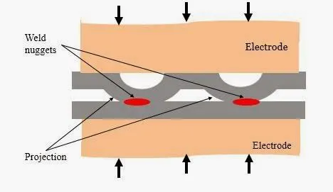
- Heat is developed mainly at the interface b/w two sheets,eventually causing the material being welded to melt,forming a molten pool,the weld nugget.
- The molten pool is contained by teh pressure applied by the electrode tip & the surrounding solid metal.
- ADVANTAGES:
- Short weld time & hence high weld speed.
- Highly adapatable to automation & robotic techniques.
- Typical BIW contains 5000 welds.
- Strength & durability of automobile largely depends on quality of RSW.
- Resistance seam welding-Resistance seam welding is a process that produces a weld at the faying surfaces of two similar metals. The seam may be a butt joint or an overlap joint and is usually an automated process. It differs from flash welding in that flash welding typically welds the entire joint at once and seam welding forms the weld progressively, starting at one end. this type of welding process is used to join the fuel tanks where the liquid type containers.
- seam welding is a resistance welding processs for h=joining metal sheets in the continuous, often la=eak tight, seam joints by directly applying opposing forces with electrodes consisting of rotary wheels.
- The current & the heat generation are localized by the peripheral shapes of the electrode wheels.
- APPLICATIONS:
- seam welding is mostly applied in manufacturing of containers ,radistors & heat exchangers etc.
- Resistance projection welding-
- Resistance projection welding, or RPW, is a form of resistance welding where the electricity, force, and time are concentrated on raised segments (or projections) to join items together.
- Projection welding is a resistance welding process for joining metal components or sheets with embossments by directly applying opposing forces with electrodes specially dsigned to fit the shapes of the workpieces.
- The current & the heat generation are localized by the shape of the workpiece either with their natural shape or with specially designed [projection.alarge deformation or collapse will occur in the projection part of the workpiece implying high.
- APPLICATIONS:
- Used for ,mechanial fixing of autobody structures eg. weldnuts.
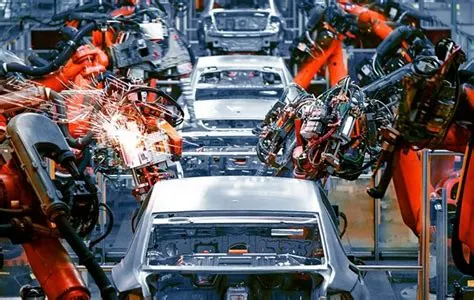
- The most common applications of large-scale resistance welding can be found in the automotive industry.
- Resistance welding in the automotive industry is probably the most common. During vehicle assembly there are three resistance welding processes that are typically leveraged: spot welding, projection welding (a variation of spot welding) and seam welding (a variation of spot welding).
- The biody side parts are joined with the spot welding by the robots almost all the parts with sheet metals are joined with resistance welding.
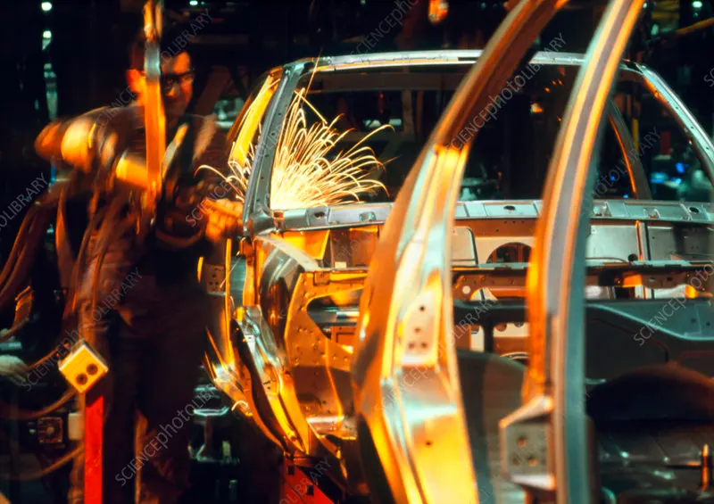
- Arc Welding. The most popular type of fusion welding is arc welding. Arc welding lives up to its namesake by relying on an electric arc to join
- ARC WELDING-
- The processes involves either consuamable or non consuamable electrodes (rod or wire)
- An arc produced b/w tip of the electrodes & work piece to be welded,by use of an AC or DC power supply.
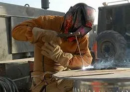
TYPES OF ARC WELDING:
- Manual metal arc welding.
- Gas-shielded metal arc welding (metal inert gas (MIG) welding).
- Gas-shielded tungsten arc welding (TIG).
- Submerged arc welding.
- Plasma arc welding.
ELECTRODES.
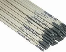
MANUAL METAL ARC WELDING:
- Manual metal arc weling (MMA or MMAW) also known as shielded metal arc welding (SMAW) .or informly as stick welding.
- Stick welding is a process where the arc is struck b/w the metal rod (electrode flux coated ( & the work piece,both the rod & work piece surface melt to create a weld.
GAS-SHIELDED METAL ARC WELDING (metal inert gas (MIG) welding.
- Metal inert gas (MIG) welding is an arc welding teechnique in which a consuamable electrode is used to weld two or more work pieces.
MIG welding makes use of the following components:
- consumable electrode.
- inert gas supply.
- welding head.
- AC or DC power supply.
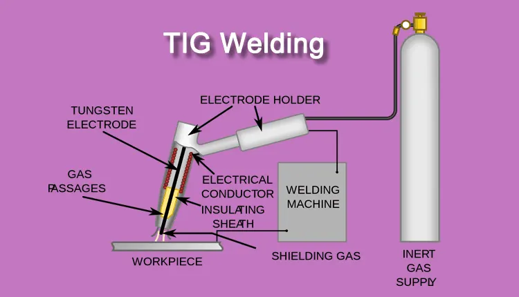
TIG WELDING
Gas tungsten arc welding (GTAW), also known as tungsten inert gas (TIG) welding, is an arc welding process that uses a non-consumable tungsten electrode to produce the weld. The weld area and electrode are protected from oxidation or other atmospheric contamination by an inert shielding gas
SUBMERGED ARC WELDING
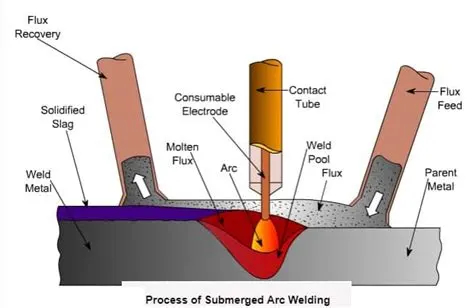
Submerged-arc welding (SAW) is a common arc welding process. that involves the formation of an arc between a continuously fed electrode and the workpiece. A blanket of powdered flux generates a protective gas shield and a slag (and may also be used to add alloying elements to the weld pool) which protects the weld zone.SAW is usually operated as a mechanised process. Welding current (typically between 300 and 1000 amperes), arc voltage and travel speed all affect bead shape, depth of penetration and chemical composition of the deposited weld metal. Since the operator cannot observe the weld pool, great reliance must be placed on parameter setting and positioning of the filler wire.
ADVANTAGES.
- Excellent quality of weld.
- Smooth and uniform finished weld.
- No spatter, no smoke.
- No Arc flash.
- High rate of utilisation of electrode wire
GAS WELDING
Gas welding is a most important type of welding process. It is done by burning of fuel gases with the help of oxygen which forms a concentrated flame of high temperature. This flame directly strikes the weld area and melts the weld surface and filler material.
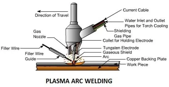
PLASMA ARC WELDING
Plasma welding is very similar to TIG as the arc is formed between a pointed tungsten electrode and the workpiece. However, by positioning the electrode within the body of the torch, the plasma arc can be separated from the shielding gas envelope. Plasma is then forced through a fine-bore copper nozzle which constricts the arc. Three operating modes can be produced by varying bore diameter and plasma gas flow rate
-
Microplasma weldingMicroplasma was traditionally used for welding thin sheets (down to 0.1 mm thickness), and wire and mesh sections. The needle-like stiff arc minimises arc wander and distortion. Although the equivalent TIG arc is more diffuse, the newer transistorised (TIG) power sources can produce a very stable arc at low current levels.
5.3-2-1 PRNCIPLE.
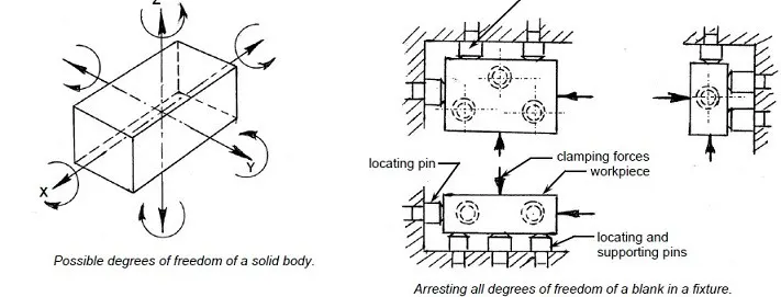
The main purpose of this principle is to fix the assembly parts stable. it should not have any degree of freem to move in any axis. by using the blocks & pins.fixed in the required points to srrest the assembly not to move.
In machining proces in order to attai the specific results the degree of freedom is constrained byusing wrk holding devices,jigs,& fixtures & locators devices, there must be a define relationship b/w cutting tool & surface of workpiece in order to perform the accurate cutting operation to achieve high precisoion inmachining the work piece mu be located accrately. it is called the locating of the workpiece. location of the components is significenet t the design of jigs,fixtures,locatorsretc. so that influences he accuracy of final product the locating device designed so that each sucessive workpiece loaded must occupy the same position in work handling devices.
LOCATING:The positional & dimensional relationship b/w work piece & cutting tool.
LOCATOR: the device establish method of part maintain the position of the workpiece in work holders such as jigs , fixture to ensure repeatdly of work holder.
The best & most cost effective method of a part location is refered to as the 3-2-1 method.
(3)Minimum: three locator blocks to establish part plane. three locators or supports ,are placed under the work piece. the three locators are usually positioned o the primary locating surface this restricts one axial movement downward.& radial movements To geather the three locators restrict five degrees of freedom.
(2)Round locating pin in a round hole that defines locatiom in four directions (-way) perpendicular to the plane previosuly established .the restricts four axial movement.
(1). Round locating pin in a slot that defines two of the directions of the other pin (2-wat) thi restricts two axial movements.
6.BODY COORDINTE SYSTEM
The body coordinate syatem as been widely used in the automotive industry for drawing of body parts,products & process design a coordinate system is a referance system consisting of a set of points ,lines & surfaces ,used to define the positions of points in space in either two or three dimensions .in general BCS is also called as car line & body line.
car line are the (grid line shown in the fixture which virtually represent the same locationib biw all the acr line on fixture display the coordinate at the corner for referance thses lines one cann easily realte the location in BIW.
some times singke line coordinate hole is given fixture that also represents the car line coordinate from that referance point fixture is made & can be inspected .body coordinate are mensioned near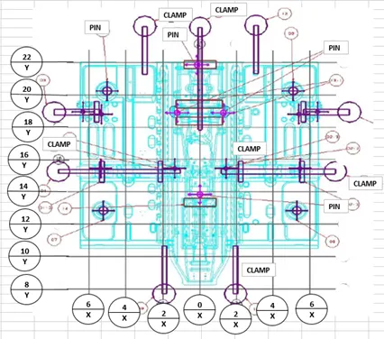
The origin of the body coordinate system will be at the center of mass. The axes of the body coordinate system will be the principal axesof the object. These axes are rotating with the object.
Body coordinate system in BIW The body coordinate system has been widely used in the automotive industry for drawing of body parts,Products and process design. A coordinate system is a reference system consisting of a set of points,lines and surfaces,used to define the positions of points in space in either two or three dimensions.With these lines one can easily relate the ,location in BIW. Some times single coordinate hole is given in the fixture ,that also represent the car line coordinates, from that reference point fixture is made and can be inspected . Body coordinate are mentioned near the hole Maintaining X,Y & Z co-ordinates in fixture is a very important factor.With these lines one can easily relate the ,location in BIW. Some times single coordinate hole is given in the fixture ,that also represent the car line coordinates, from that reference point fixture is made and can be inspected . Body coordinate are mentioned near the hole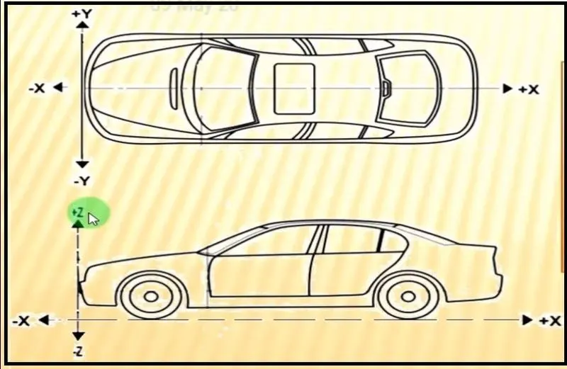
x= longitudinal direction [(Fore & After - F/A ) or (Front O line - FOL)]
Y=Transverse direction [(cross car- C/C )or (Centre O line -COL)]
Z = verticl direction [(up & down -U/D) or (Bottom O line -BOL)]
the origin of the body coordinates system (OX) is defined at the front centre of a vehicle. it indicates a length of a car & the coordinate system (OZ) is below its underbody indicates heigtof car.& the coordinate system (OY) its starting point is the centre of a car.body indicates width of car.
7.BODY PLANES SYSTEM & ITS ESSENTIALS.
- Body planes are the referance planes in an automotive car.these planes are used to define the GD&T of all the car parts in a automotive domin.
- Body planes are 3 mutually perpendicular imaginary planes .ythese are generally considred to be present at the driver position or sometimes at the engine loction or at the front end of the car depeding on the customer.
- The measurement from the body planes to the parts are called as body line dimension
These body planes are called as
- FOL Front "O"line
- COL Centre "O"line
- BOL Body "O" line
- The measurements along FOL or X axis is called as F/A Front Aft
- The measurement along COL or Y axis is called as C/C cross car.
- The measurement along BOL or Z axis is called as U/DUP down.
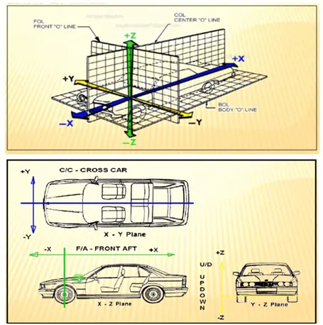
THE BODY LINE DIMENSIONS ARE ESSENTIAL FOR THE REASONS STATED BELOW.
- it defines the exact position of each productin the vehicle w.r.t a fixed origin.
- it ensures flawless design for the assembly.
- while designing lines ,all the deign are carried out relative to the bodyline viz,fixtures turn tables.etc.
- it assists in easy location of different parts in a vehicle.
- it aims creating a standardized parts in a vehicle.
- it asssts of quality checks.
qulity check is done by cmm machine & takes the approval from it weather the quality of the model is ok or not.the pins should be arranged accordig to the holes respectively with out any mis dimensions axs line. toget accurate quality check with the cmm machine.