Week 2:- BiW Fixture Basics Challenge
INTRODUCTION TO BASICS OF BIW FIXTURES
OBJECTIVES:
- The main motive or objective of this challenge is to understand the basics of the BIW fixtures.
- To answer the questions that are asked in the challenge.
- To prepare a report by attaching all the images when required.
1. PROCESS OF PROJECT EXECUTION ACTIVITY:
PROJECT ACTIVITIES: Project activities are those activities that are being practiced or followed in general project's where BIW fixturing and tooling is involved and it's starts with basic requirments and ends with handling the final product to the customer. The stages that are involved in the project activities and the sequence are shown in below flow chart,
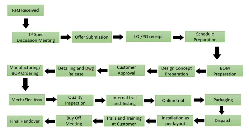
1. RFQ RECEIVED: RFQ stands for Request For Quotation where a customer gives us requirements, specifications, features etc., in the form of documents or data. We have to study and work on the data about the technical offer, commercial offer based on that how we are proceeding and executing that project, what would be the timeline of the project etc., have to be determined in this stage.
2. OFFER SUBMISSION: After carefull study of the RFQ we will prepare a quotation and we will submit that to the customer. The customer have to check all the details like timeline, cost, requirements and specifications in the offer carefully that they are accceptable to him or not. After that he proceeds further to confirm the order.
3. LOI/PO RECIEPT: Here LOI stands for Leter Of Intent and PO stands for Purchase Order. In this stage we will recieve input data fromthe customer such as 2D drawings 3D data, design stands etc.,
4. SHEDULE PREPARARION: Once we recieve the PO, we will start sheduling the work plans and all other activities. There moght be a chance that some activities may get delayed due to previous activities. So that we have to maintain a back up to match the delivary date given to the customer and actual delivary date. Proper sheduling is required to complete the project in time.
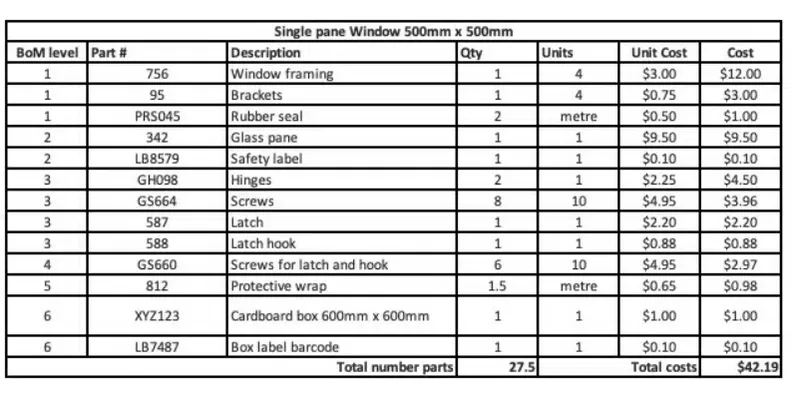
5. BOM PREPARATION: BOM stands for Bill Of Materials. In this stage we have to specify the components what we required and parts we have to arrange and the type of cylinders required and in which number they are needed. Here i am attaching an example of bill of materials table.
6. DESIGN CONCEPT PREPARARTION: Based on the data which we have from the previous stages of the process such as 2D details, 3D details, parts that are available and actuation systems, design standards and manufacturing standards that are specified by the customer we will prepare the concept for our design and we have to submit that to the customer.
7. CUSTOMER APPROVAL: The design concpet which we have prepared previously stage is submitted to the customer, if he accept the concept we can proceed further. If he suggets sny changes or modifications then we have to update the design concept according the customer's satisfaction.
8. DETAILING AND DWG RELEASE: Once customer approves the design concept, then we have to prepare detailed drawings and send them to manufacturing team. where they start manufacturing the parts or components.
- 9. MANUFACTURING/ BOP ORDERING: Here in this stage all the components have to be arranged by manuacturing or by buying the products such as cylinders and other things from the sellers. After that a basic quality check is performed on the parts by the quality team and they have to approve all the parts before assembling the parts.
10. MECH/ ELE ASSEMBLY: As per the drawings/ designs assembly has to be done properly.
11.QUALITY INSPECTION: After assembly again a quality inspection is performed on the assembly to check the quality pf the assembly and to check the measurments by using CMM.
12. INTERNAL TRAIL & TESTING: In this stage the assembly is placed in fixtures, to check weather the assembly is made properly or not, pins are getting into holes or not and all other such things are tested in this stage. If everything is ok, then we go for welding or other joining processes.
13. ONLINE TRAIL: In online trail everything is done through the control panel in an automated mode. Everything should work through electrical connectionsand as per sequence the process is defined.
14. PACKAGING: Proper packaging is necessary because the product may get hamperred in trasportation so that the product may get damaged asthetically or functionally. So that we have to package the product in a proper manner.
15. DISPATCH: The product is dispatched and handled over to the customer.
16. INSTALLATION AS PER LAYOUT: The dispatched final product has to be installled in the customer's place as per the layout given in the LOI/PO stage
17. TRAIL & TRAINING AT CUSTOMER: Number of trails has to be performed on the product so that we can know and determine weather the product is giving the intended output or not. Training for operators and staff members and engineers to let them understand how the peocess is working and sequence of work and eevrything.
18. BUY OFF MEETING: In this meeting the customer will specify anything to be incorporated or somethong else needed or something to be added or something is missing as prescribed in LOI/PO or the customer wants to add extra features, in this case we have rise our quotation as per the request.
19. FINAL HAND OVER: After all the things and changes have been performed on the final product the product is handled over to the customer finally..
2. TYPES OF JOINING PROCESSES:
The durability and performance of any structure is largely dependent on the quality and the design of the component joints. Whole structure can not be made in one piece.
- Two fundamental options for joining materials and componets are
- Mechanical joining techiques
- Metallurgical joining techniques.
MECHANICAL JOINING TECHNIQUES:
Mechanical joining includes bolting, riveting, caulking, shrink fitting, and folding, all of which join workpieces by using mechanical energy. The different types of mechanical joints are given below
- Riveting
- Caulking
- Bolting
- HEMMING
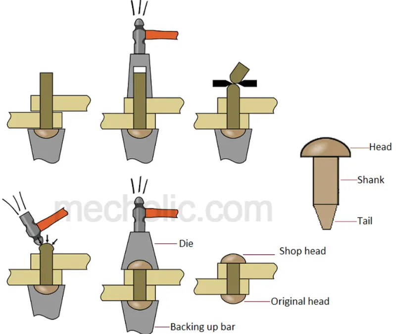
RIVETING: Riveting is a forging process that may be used to join parts together by way of a metal part called a rivet. The rivet acts to join the parts through adjacent surfaces. A straight metal piece is connected through the parts.
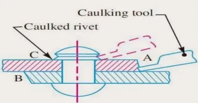
CAULKING: In order t make joints leak proof or fluid tight in pressure vessels like steam boiler, air tanks etc., a process known as caulking is employed. In this process narrow blunt tool caulking tool , about 5 mm thick and 38 mm in breath is used. The edge of the tool is ground to an angle of 80 degrees. The tool is moved after each blow along the edge of the plate, which is planed to a bevel of 75 to 80 degree, to facilitatethe forcing down to edge. It is seen that the tool burrs down the plate at A as shown in the figure, forming both the metal in metal joints. The heads of the rivet as shown at C are also turned down with a cuclking tool to make a joint steam tight. A great care is taken to prevent injury to the plate belowthe tool.
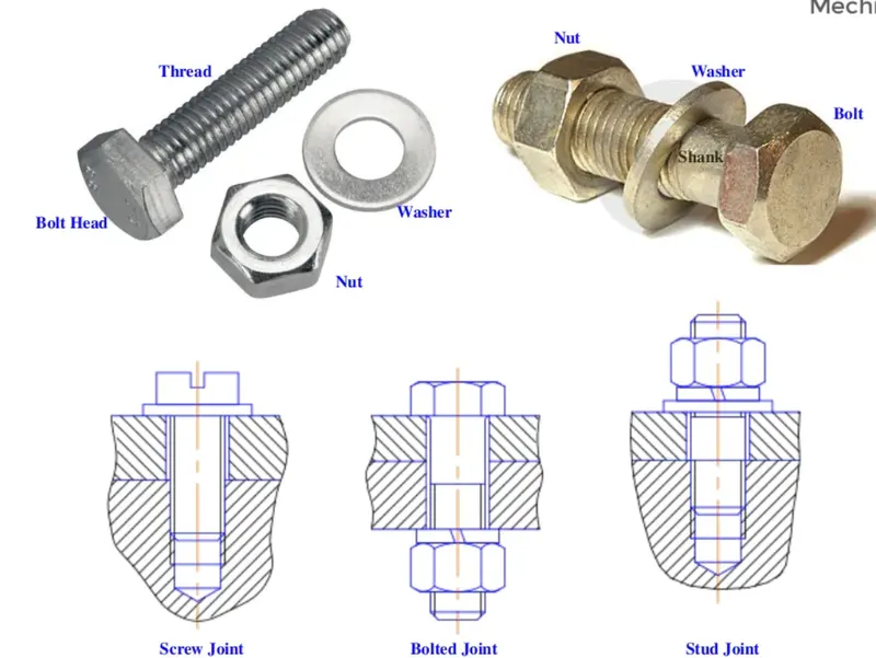
BOLTING: Typically, a bolt is tensioned (preloaded) by the application of a torque to either the bolt head or the nut. The applied torque causes the bolt to "climb" the thread causing a tensioning of the bolt and an equivalent compression in the components being fastened by the bolt.
In another way it is defined as In this metal joining process, the metallic parts are joined together by means of Bolt/Screw (and/or nut). This Process is widely used in assembling of parts are to be joined temporarily or joints which require periodic maintenance. Two main types of loads on bolted joints: Tension Shear Bolting.
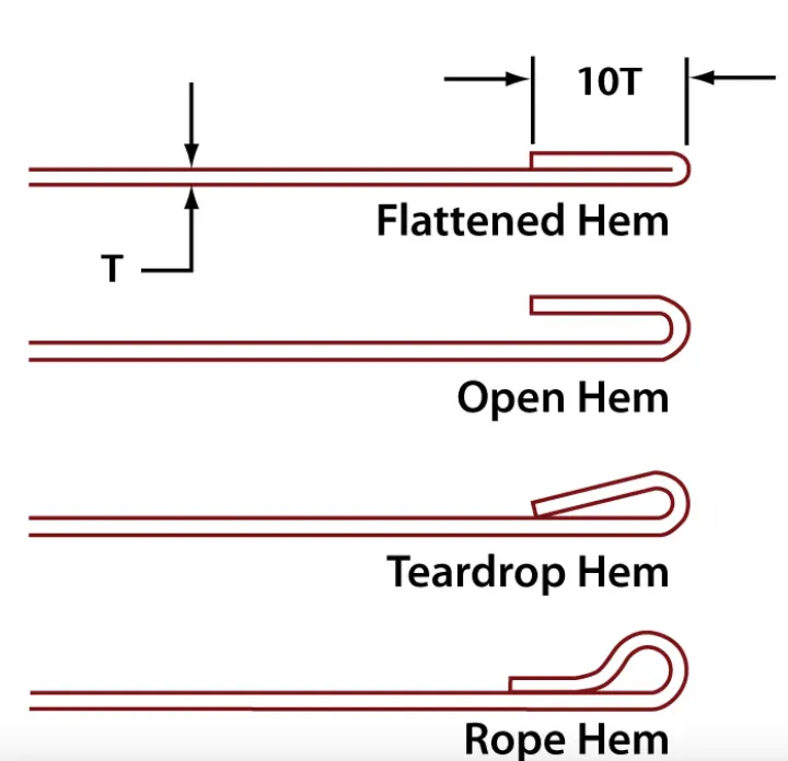
HEMMING: Hemming and seaming are two similar metalworking processes in which a sheet metal edge is rolled over onto itself. Hemming is the process in which the edge is rolled flush to itself, while a seam joins the edges of two materials.
- METTALURGICAL JOINING TECHNIQUES:
Metallurgical joining includes fusion welding, pressure welding and brazing/soldering which use different energies. The different types of mettalurgical joining techniques are given below,
-
Fusion welding - Electrical energy
-
- Arc welding
- Electron beam welding
- Chemical energy
-
- Gas welding
- Light energy
-
- Laser welding
Pressure welding - Electrical energy
-
- Resistance welding:
-
- Resistance spot welding
- Projection welding
- Seam welding
- Upset welding
- Flash welding
- Chemical energy
-
- Explosion welding
- Mechanical energy
-
- Cold pressure welding
- Friction welding
- Friction stir welding (FSW)
- Ultrasonic welding
- Diffusion welding
Brazing/soldering - Electrical energy
-
- Induction heating brazing (soft brazing = soldering)
- Chemical energy
-
- Torch brazing (flame brazing)
- Light energy
-
- Light beam brazing
- Laser brazing
3. RESISTANCE WELDING & IT'S APPLICATIONS IN THE AUTOMOTIVE SECTOR:
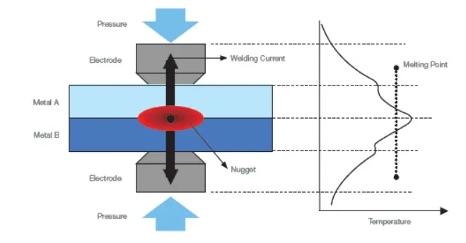
- Resistance welding is a welding technology which is widely used in manufacuring industry for joining metal sheets and components.
- The weld is made by conducting a strong current through the metal combination to heat up and finally melt the metals at localized points, predetermined by the design of the electrodes and/ or the workpieces to be welded.
- A force is always applied before, during and after the application of current to confirm the contact area at the weld interfaces and, in some applications, to forge the workpieces.
Principle:
All resistance welding like spot welding, seam welding, projection welding etc. are worked on same principle of heat generation due to electric resistance. When a current passes through electric resistance, it produces heat. This is same principle which is used in electric coil. The amount of heat produced is depends on resistance of material, surface conditions, current supplied, time duration of current supplied etc. This heat generation takes place due to conversion of electric energy into thermal energy. The heat generation formula is
H = I2RT
Where
H = Heat generated in joule
I = Electric current in ampere
R = Electric resistance in Ohm
T = Time of current flow in second
This heat is used to melt the interface metal to form a strong weld joint by fusion. This process produces weld without application of any filler material, flux and shielding gases.
Types:
There are four main type of resistance welding. These are
Spot Welding:
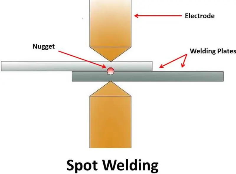
It is simplest type of resistance welding in which the work pieces are held together under pressure of anvil face. The copper electrodes are brought in contact with work piece and current start to flow through it. The work piece material applies some resistance in flow of current which cause local heat generation. At the interface surfaces the resistance is high due to air gap. The current start to flow though it which melt down the interface surface. The amount of current supply and time should be sufficient for proper melting of interface surfaces. Now the current stopped to flow but the pressure applied by electrode maintained for a fraction of second, while the weld rapidly cooled. After it, the electrodes remove and brought to contact at other spot. It will create a circular nugget. The nugget size depends on size of electrode. It is generally about diameter 4-7 mm.
Seam Welding:
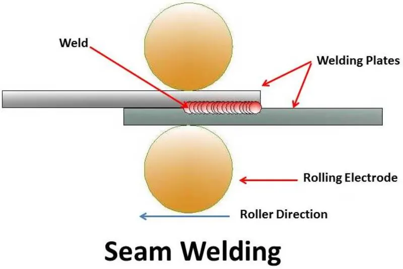
Seam welding is also called continuous spot welding in which a roller type electrode is used to flow current through work pieces. First the rollers are brought in contact with work piece. A high ampere current is passed through these rollers. This will melt the interface surfaces and form a weld joint. Now the rollers start rolling at work plates. This will create a continuous weld joint. The timing of the weld and movement of electrode is controlled to assure that the weld overlap and work piece does not get too hot. The welding speed is about 60 in/min in seam welding. It is used to create air tight joints.
Projection Welding:
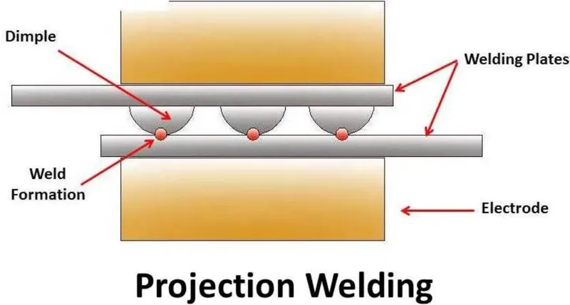
Projection welding is same as spot welding except a dimple is produced on work pieces at the location where weld is desired. Now the work pieces held between electrode and a large amount of current pass through it. A small amount of pressure is applied through electrode on welding plates. The current pass through dimple which melt down it and the pressure causes the dimple flatten and form a weld.
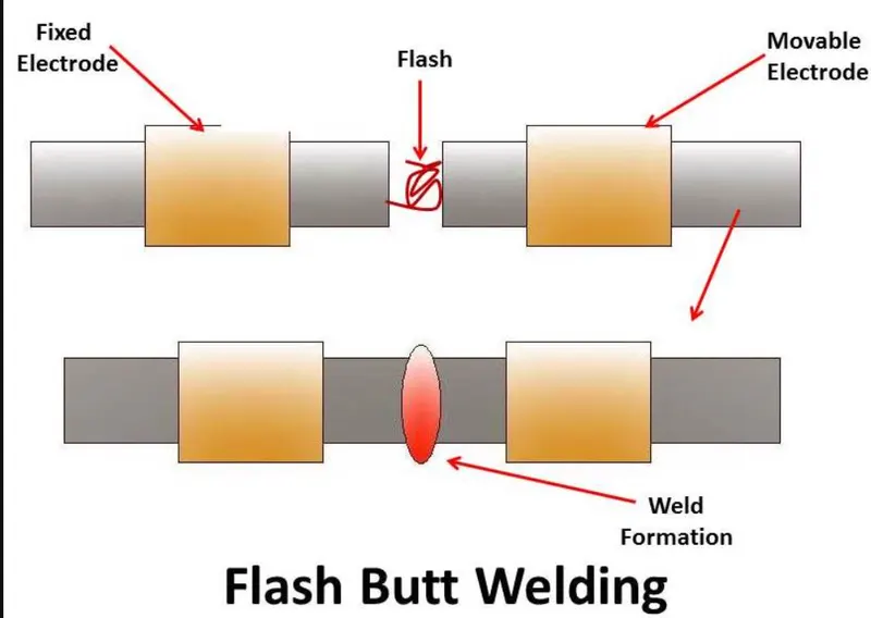
Flash butt Welding:
It is another type of resistance welding which is used to weld tubes and rods in steel industries. In this process, two work pieces which are to be welded will be clamped in the electrode holders and a high pulsed current in the range of 100000 ampere is supplied to the work piece material. In this two electrode holders are used in which one is fixed and other is movable. Initially the current is supplied and movable clamp is forced against the fixed clamp due to contact of these two work pieces at high current, flash will be produced. When the interface surface comes into plastic form, the current is stopped and axial pressure is increased to make joint. In this process weld is formed due to plastic deformation.
Application:
- Resistance welding is widely used in automotive industries.
- Projection welding is widely used in production of nut and bolt.
- Seam welding is used to produce leak prove joint required in small tanks, etc.
- Flash welding is used to welding pipes and tubes.
Advantages and Disadvantages:
Advantages:
- It can weld thin (0.1 mm) as well as thick (20mm) metals.
- High welding speed.
- Easily automated.
- Both similar and dissimilar metals can be weld.
- The process is simple and fully automated so does not required high skilled labor.
- High production rate.
- It is environment friendly process.
- It does not require any filler metal, flux and shielding gases.
Disadvantages:
- High equipment cost.
- The thickness of work piece is limited due to current requirement.
- It is less efficient for high conductive materials.
- High electric power required.
- Weld joints have low tensile and fatigue strength.
4. FUSSION WELDING - TYPES AND APPLICATIONS:
Fusion welding is a process that uses heat to join or fuse two or more materials by heating them to melting point. The process may or may not require the use a filler material. External application of pressure is not required for fusion welding processes, except for resistance welding, where substantial contact pressure is required during welding for sound joining.
In the fusion welding or no pressure welding process, the material at the joint is heated to a molten state and allowed to solidify. These welding are also known as liquid state welding process. This includes gas welding, arc welding, thermite welding etc.
The fusion welding is bascically devided into three types they are
- ELECTRICAL ENERGY
- CHEMICAL ENERGY
- LIGHT ENERGY
ELECTRICAL ENERGY:
Again the electrical energy type fusion welding is divided into two types
- Arc welding
- Electron beam welding
ARC WELDING:
Arc-welding is the most common method of fusion welding. Arc welding lives up to the hype; it uses an electric arc to connect two or more parts. And the arc welding is again sub divided to different types as listed below
- MANUAL ARC WELDING:
Manual Metal Arc (MMA) welding is the most flexible and one of the most widely used arc welding processes. It involves striking an arc between a covered metal electrode and a workpiece.
The heat of the arc melts the parent metal and the electrode which mix together to form, on cooling, a continuous solid mass. The central metal electrode or core wire acts as a consumable, providing the filler metal for the weld. MMA welding can be used to join most steels, stainless steels, cast irons and many non-ferrous materials. For many mild and high-strength carbon steels, it is the preferred joining method.
An electric arc is produced between a metal electrode, carrying a high current, and the workpiece to be joined. Under the intense heat of the arc temperature (2700–5500°C), a small area of the base metal is brought to the melting point. At the same time, the end of the electrode is melted and droplets of molten metal pass through the arc to the base metal. A flux coating on the electrode provides a gaseous shielding against oxidation.
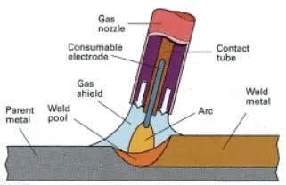
- METAL INERT GAS (MIG) WELDING: Metal Inert Gas (MIG) is also known as gas metal arc welding (GMAW). This type of welding is basically an arc welding process that joins two metals. This is done by heating the metals with the help of an arc. This arc is formed between the surface to be welled and a continuously fed filler electrode. This type of welding uses a shielding gas to protect the molten pool of weld metal from reacting with elements present in the atmosphere. MIG welding requires a DCEP (Direct Current Positive Electrode), also known as Reverse Polarity.
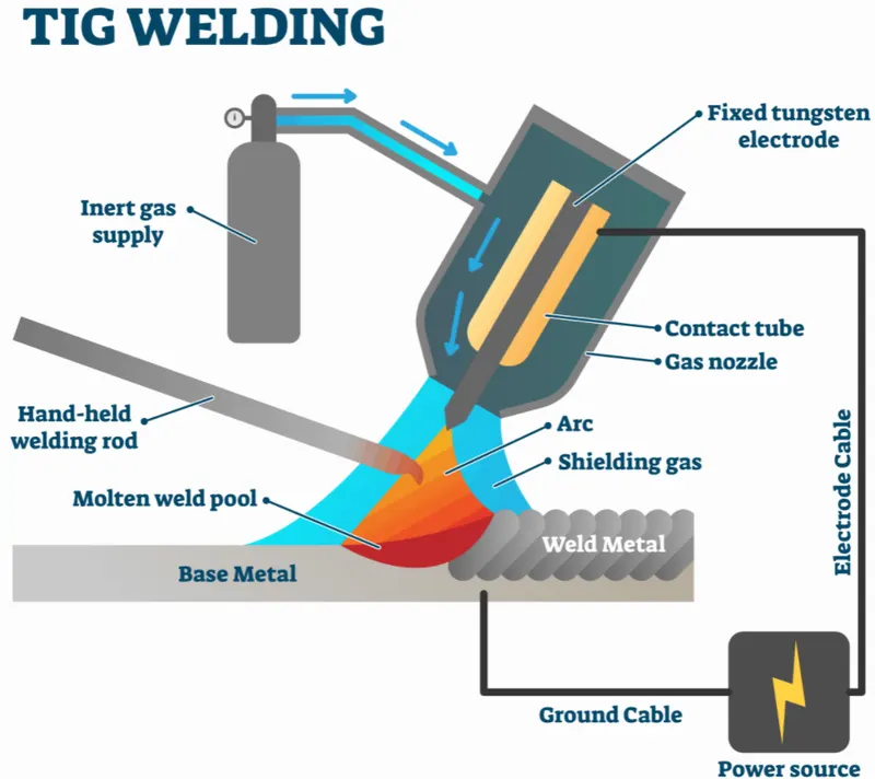
- TIG WELDING: TIG stands for Tungusten Inert Gas. TIG welding is an arc welding method that produces the arc between the base plate and the electrode using a tungsten electrode that is not consumable. This inert shielding gas is used to shield against oxidation or other pollution in the atmosphere.
This method can be used viscerally on lean parts, but for heavier components, it will involve inserting a tube, rod, or consumable.
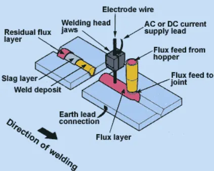
- SUBMERGED ARC WELDING: A commonly utilized arc welding method, SAW utilizes an actively fed usable electrode and a fusible flux blanket which, when molten, becomes permeable and creates a current path between the electrode and the workpiece. The plasma, while removing ultraviolet radiation and gases, also stops staining and fires.
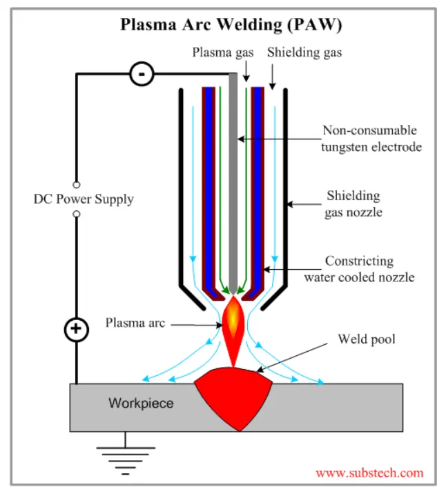
- PLASMA ARC WELDING: This method utilizes an electric arc produced between a torch nozzle and an electrode. The gas (typically argon) within the area is ionized by the arc, producing what is called a spark. It is then pushed via a fine bore copper nozzle, which inhibits the arc and guides it to the workpiece, enabling the spark arc to be isolated from the shielding gas (typically created from a combination of hydrogen and argon).
CHEMICAL ENERGY: Chemical energy welding is explained in below steps,
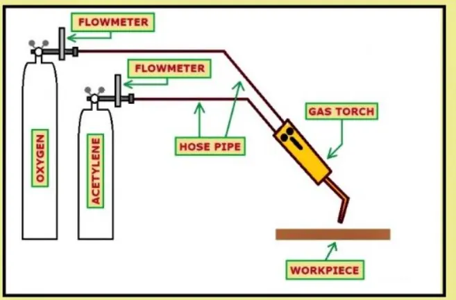
Oxy-fuel welding
Often referred to as gas welding and oxyacetylene welding, oxy-fuel welding is a process that utilizes a blowpipe or torch that can be held in hand with a combination of acetylene and oxygen that burns to form a flare. Oxyfuel welding, which is a form of solvent-based fusion welding, requires the utilization of a flame to melt and connect surfaces, using oxygen as the fuel source.
Naturally, fire requires oxygen, which is the foundation on which oxyfuel welding operates. The fire is fueled by oxygen to produce a hot flame greater than four thousand five-hundred degrees Fahrenheit.
Oxyfuel welding generally uses a mixture of combustible gas and oxygen to produce a hot flame for materials to connect together.
LIGHT ENERGY: The light enrgy type welding is the laser beam welding which is explained below,
The laser beam welding works on the principle that when the electrons of an atom are excited by receiving some energy. And then after some time when it returns to its ground state, it emits a photon of light.
The concentration of this emitted photon is increased by the excited emission of radiation and we get high energy focused laser beam. The light amplification by stimulated emission of radiation is named as a laser.
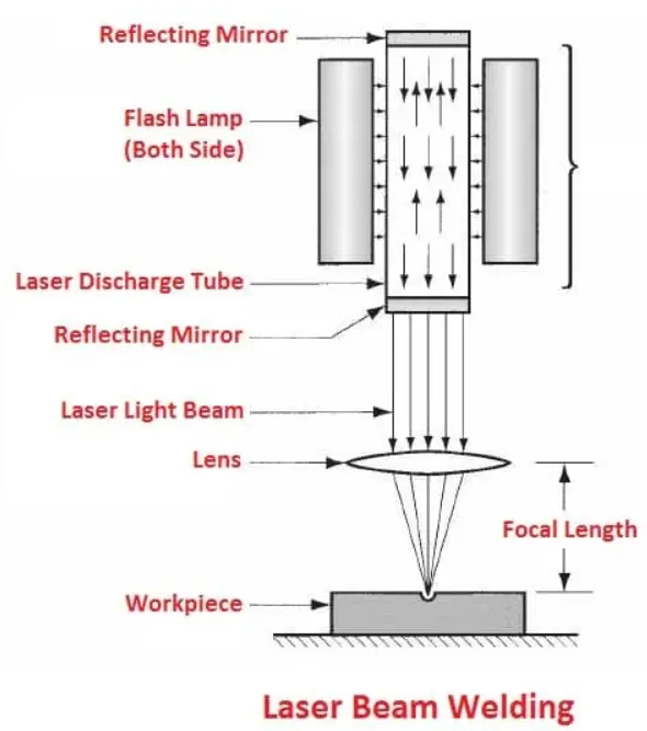
Initially, the welding machine is setup (between the two metal pieces to join) at the desired location. Later setup, a high voltage power supply is applied to the laser machine to perform an operation.
The lens is used to focus the laser into the area where welding is required. CAM is used to control the speed of the laser and workpiece table during the welding process.
Advantages Of Fusion Welding:
1) Fusion Welding can be used to join dissimilar materials easily.
2) External filler material can be added easily.
3) No external pressure is needed.
4) Using this process, more than two components can be welded at a step.
Disadvantages Of Fusion Welding:
1) Due to intense heating and subsequent melting, many mechanical and metallurgical properties are affected.
2) Because of excessive heat input, high distortion takes place.
3) Noticeable heat affected zone exists around the weld bead due to excessive heat.
4) Welding two dissimilar metals is difficult specially if the metals have different melting points and coefficient of thermal expansion.
APPLICATIONS: Fusion welding processes are commonly used across a range of industries including aerospace, automotive and construction amongst others. Used to join metals for a variety of applications, fusion welding is also used to create artwork by a growing community of artists.
5. 3-2-1 PRINCIPLE OF FIXTURES DESIGN:
For a fixture designer, the major portion of design time is spent deciding how to locate thw work piece in the fixture.
Any rectangular body many have three axis along x-axis, y-axis and z-axis. It can more along any of these axes or any of its movement can be released to these three axes. At the same time the body can also rotate about these axes too. So total degree of freedom of the body along which it can move is six. For processing the body it is required to restrain all the degree of freedom (DOF) by arranging suitable locating points and then clamping it in a fixed and required position. The basic principle used to locate the points is explained below.
The degrees of freedom of body are given below
1. A body can translate along positive direction and negative direction of X- axis, Y- axis, Z-axis. So from here we have six degrees of freedom. and this six movements are called translation movements.
2. similar to the above statment a body in space can rotate along the three axis so that we can have another six movements and they are called as rotational movements.
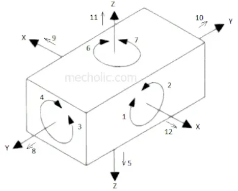
To be make th body stable now we have to arrest these 12 degrees of freedom. This can be done by using 3-2-1 principle and it is alos called as six point principle.
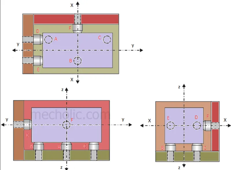
Pins A, B, C on the base plane ( a plane parallel to the plane which contains X and Y axis) restrict the rotation of component about X axis and Y axis. It also limit the downward movement of component along z axis. Ie. 1,2,3,4 and 5 degrees of freedom is restricted.
Pins D, E is in plane parallel to the plane containing X and Z axes. It prevents the rotation of component about Z axis (6, 7 degree of freedom) and the movement of the body in along Y axis towards one direction (8 degree of freedom).
The last pin F is in a plane parallel to plane contains Y and Z axes. It restricts the movement component along X axis in one direction.
Three remaining degree of freedom 10, 11, 12 is unrestricted. It facilitates the loading of the component in the fixture. This three degree of freedom may restrict after loading of component by using clamping devices.
6. BODY CO-ORDINATE SYSTEM:
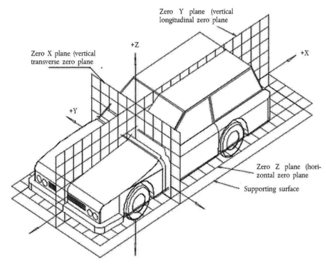
The body coordinate system has been widely used in the automotive industry fpr drawing of body parts, product and process design. A coordinate syste is a reference system consisting of a set of pointd, lines and surfaces, used to define the positions of poits in space in either two or three dimensions.
In general BCS is also called as car line and body line.
A body coordinate system is as shown in below figure,
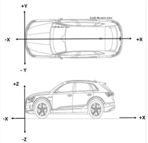
here
- X is longitudinal direction so that we can have the lenght of the car.
- Y is the transverse direction and from that we get the width of the car
- Z is the vertical direction from that we can specify the height of the car.
The intersection of these three lines is considered as the origin of the vehicle. the origin is not same in all the situation, some companies may take origin at the centre of the vehicle.
7. BODY PLANE SYSTEM AND IT'S IMPORTANCE:
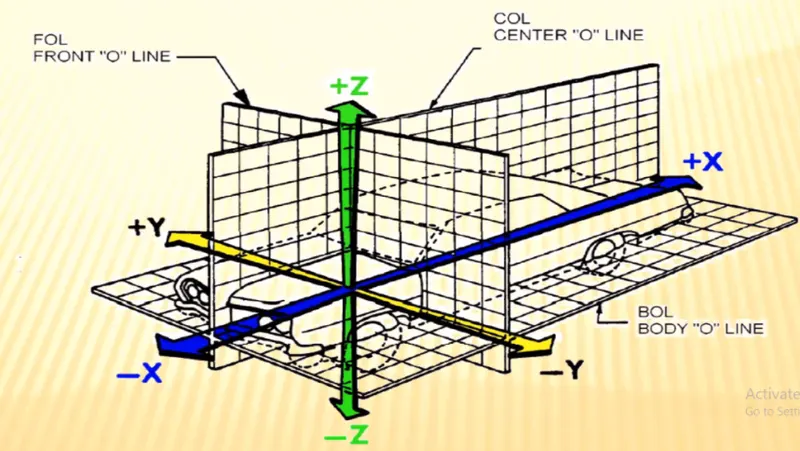
- Body planes are the reference planes in an automotive car. These planes are used to define the GD & T of all car parts in ana automotive domain.
- Body planes are three mutually perpendicular imaginary planes. These are generally considered to be present at the driver position or sometimes at the engine location or at the front end of the car, depending on the customer.
- The measurment from the body planes to the parts are called as bodyline dimenssions
- These body planes are called as
1.FOL Front "O" Line
2.COL Centre "O" Line
3.BOL Body "O" Line
- The measurment along FOL or X axis is called as F/A Front Aft
- The measurment along COL or Y axis is called as C/C Cross Car
- The measurment along BOL or Z axis is called as U/D Up DOWN.
IMPORTANCE:
- It defines the exact position of each product in the vehicle w.r.t a fixed origin
- It ensures flawless design for assembly
- While designing lines, all the desings are carried out relative to the bodyline, viz., fixtures, turn tables, etc.,
- It assists in easy location of different parts in a vehicle.
- It aims in creating a standardized system
- It assists in quality checks.