Week 2:- BiW Fixture Basics Challenge
1. process of project execution activity
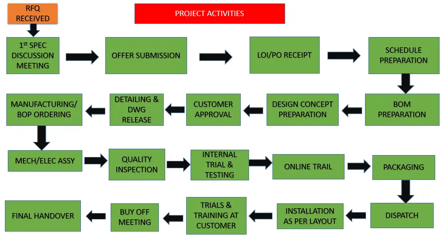
Steps for prject execution
The process of project execution activity involves series of steps as discussed below
1) RFQ received: Request for Quotation is the first and foremost step involved in project execution. In this step the customer quotes his
requirements, specifications, Technical offer, commercial offer, expected timeline of the project and other detailing in form of documents.
2) Istspec discussion meeting: After receiving the RFQ the discussion meeting will be carried out on technical offer, commercial offer,
project execution, timeline required to complete the project and will be finalized. In this meeting the time required all the steps from rough
drawing to final manufacturing are considered and cost and time minimization will be given more priority in this discussion.
3) Offer submission: The Finalized results of the 1' spec meeting will be documented and submitted to the customer for review and
feedback.
4) LO1/PO Receipt: The offer letters received to the customer will be reviewed in all aspects and best suited will be approved and Purchase
order of the project will be sent.
5) Schedule preparation: After receiving the PO the project schedule preparation will be done to meet the deadlines and to complete the
project. All the steps in the project are taken into account like po receipt, 1* spec design meeting, design date analysis, 3D design preparation
& simulation etc. the time required to finish the individual activity is calculated. And then total time will be calculated to check whether the
project can be finished in specified time or not. If it seems to be not possible alternative plans are also to be prepared. These alternative
plans come into action in project completion whenever there are deviations.
6) BOM preparation: Bill of material is prepared for the project by considering each and every step and it will be listed out.
7) Design concept preparation: Based on the customer requirements and specifications the design of the project and details of the project
are prepared in this step and sent for the approval of the customer.
8) Customer approval: In this step customer reviews the design and check whether the design fulfills the requirements or not according to
the technical offer. If everything is good then customer gives the approval otherwise suggestions and corrections will be sent on which we
have to work on and again we have to sent for approval. This goes until we get the final approval from the customer.
9) Detailing & Drawing release: After the customer approval. Detailed drawings and designs will be released of all the parts required. Like
dimensions, quantity, Specifications etc.
10) Manufacturing /BOP ordering: In this step the manufacturing process begins. Before that the required parts like motors, cylinders,sensors, gripper etc. for manufacturing are ordered as per the design specifications.
11) Mechanical/ Electrical.assembly: In this step all the parts received from BOP ordering will be analyzed for quality check and then the
mechanical and electrical assembly of the parts will be done.
12) Quality inspection: After the assembly, the assembled part will be done with quality checks. In this all the dimensions, positional
accuracy, Coordinates are checked by using CMM machine. Once all the quality checks are passed then only it will be sent to next step
otherwise it will be sent back for obtaining good assembly.
13) Internal trial & testing; In this step, internal trials are done on the fixture to evaluate its operational feasibility. For this they perform
various simulations and manual trails for the testing of the fixtures.
14) Online trial: It is done in automated mode by using electrical connections. The process sequence is checked as per the defined way in
design. This is done Infront of Customer to take their approval as well.
15) Packaging: The assemblies are packed in proper manner in such a way that no damage occurs during transportation. Otherwve a small
damage will lead to distortion of the geometry of the fixture and also the functionality of the fixture. Hence the proper packaging is very
important.
16) Dispatching: Once the packaging is done the fixture will be dispatched to the customer address.
17) Installation as per layout: layout is the space defined for the parts like fixture, robots etc., The layout is designed by considering the
functionality, application, process sequence etc. Hence installation is to be done as per the layout.
16) Inals & training at customer: Production trials are performed at customers end after the proper installation. In technical offer we have
specified the quality benchmarks, the capability of the fixture for production etc. The trials are done to check and show the capability of the
fixture to the customer. After the trials the training is given to the operator, staff & engineer for the process sequence, how the fixture works.
loading & unloading of the part etc.
17) Buy off meeting: In this meeting the we allow the customer to ask their doubts and also, we provide additional information related to
project. By the end of the meeting all the details and doubts will be cleared to satisfy the customer and hep to proceed further with the
product.
18) Final Hand over: In this step the product is finally handed over to the customer.
2. types of joining processes
| Metallurgical joining (welding) | Fusion welding |
|
|---|---|---|
| Pressure welding |
|
|
| Brazing/soldering |
|
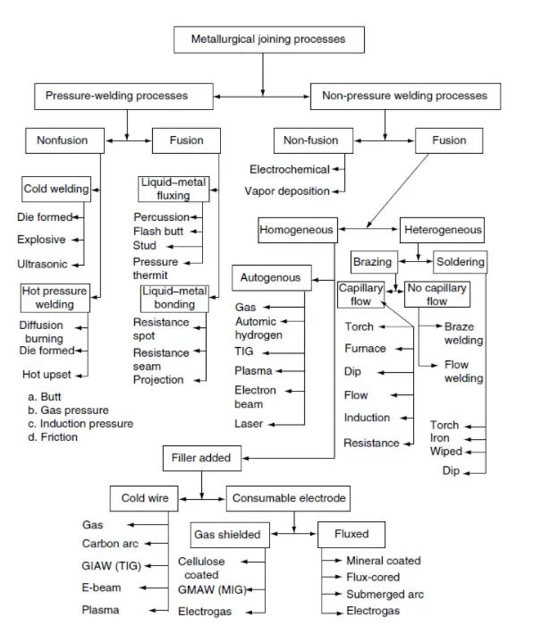
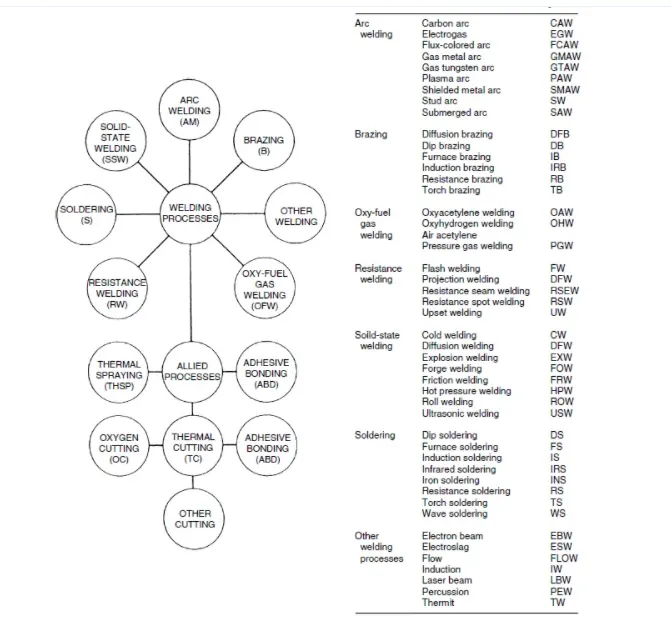
Welding
- Welding is a metal joining process in which two or more parts are joined or coalesced at their contacting surfaces by suitable application of
heat of/and pressure. - Some times, welding is done just by applying heat alone, with no pressure applied
- In some cases, both heat and pressure are applied; and in other cases only pressure is applied, without any external heat.
- In some welding processes a filler material is added to facilitate coalescence
Advantages of welding
- Welding provides a permanent joint
- Welded joint can be stronger than the parent materials it a proper filler metal is used that has strength properties better than that of parent
base maters and if detect less weldngs done - It is the economical way to join composents in terms of material use and fabricason costs. Other methads of assembiy require, lo
cample, driing of holes and usape of rivets or bolts which will produce
Disadvantages of welding
- LAbOur cost are more Bince manual welding is done mos ty
- Dangerous to use because of presence olhahhealand pressure
- Ossembly is not possible is welding, produces strong onti
- Some of the wilding defects cannot be identted which wit reduce the strength
Types of welding
- Wielding processes can be broadly classified into 1) fusion welding, and (2) sold state welding
Fusion welding
- Fusion welding heat is applied 10 melt the base metals in miry fusion welding processes a felermetalis added to the molten
pool during willing to facktate the process and provide stength to the welded joint. When no feer metal is used, that fusion welding
atian is referred to as autonenous weld
Arc welding
- In this operation, electric are is used to produce heat energy and the base metal is heated. Sometimes, both pressure and heat are
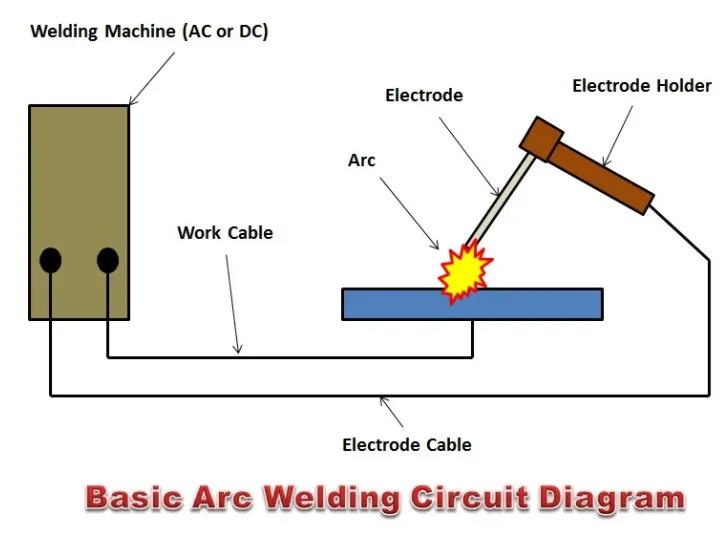
• It is a fusion welding process in which the melting and joining of metals is done by the heat energy generated by the arc between the
work and electrode.
• An electric are is generated when the electrode contacts the work and then quickly separated to maintain the gap. A temperature of
5500°C is generated by this are. A
• This temperature is sufficient to melt most of the metals. The molten metal, consisting of base metal and filler, solidifies in the weld
region. In order to have seam weld, the power source moves along the weld line.
Electrodes
Two types of electrodes are used: consumable and non-consumable.
Consumable electrodes
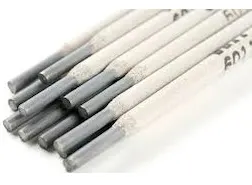
• Present in rod or wire form with 200 to 450 mm length and less than 10 mr diareter. This is the source of filler rod in are welding,
The electrode is consumed by the arc during the welding, process and added to the weld joint as filler metal.
The consumable electrodes will be changed periodically as it is consumed for each welding trials. This becomes a disadvantage for
welder and reduces the production rate.
Non consumable electrodes
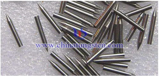
• The electrodes are not consumed during are welding. Though this is the case, some depletion occurs because of vaporization.
• Filler metal must be supplied by means of a separate wire that is fed into the weld pool.
Arc welding processes with consumable electrodes
Shielded metal arc welding (SMAW)
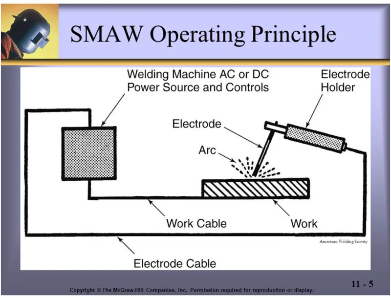
Applications
ship building, construction. machine structures etc.
Materials
grades of steel, stainless steel etc, are welded. Al, Cu. Ti alloys are not welding using SMAW
Disadvantages
Repeated change of electrodes, current maintained in typical range
Gas metal arc welding
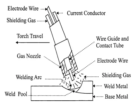
-• Base Metal
• Shielding gas: Helium, Argon, mixture of gases; used mainly for Al alloys.
• As compared to SMAW, GMAW can be used for multiple weld passes as there is no deposition of slag and hence no brushin
involved.
Advantages
• Autoration of welding possible as continuous weld wires are used, and not sticks as in SMAW.
• Also called MIG (metal inert gas) welding, CO2 welding, (when C02 is used).
Flux cored arc welding(FACW)
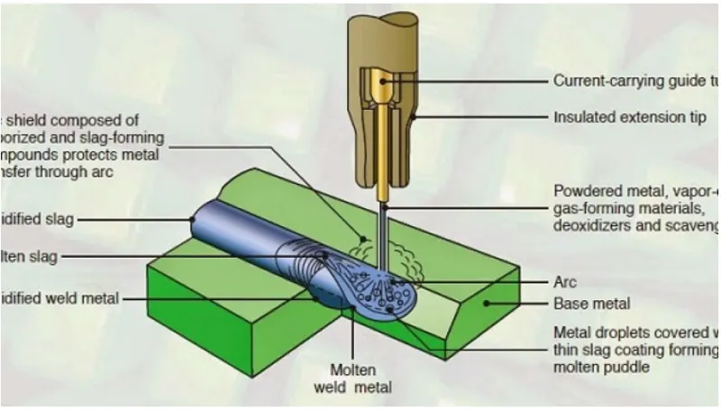
• Are welding process in which the electrode is a continuous consumable tubing that contains flux.
• The arc shielding was provided by the flux core. The core also includes ingredients that generate shielding gases for protecting the arc.
• Shielding is done from externally supplied gases. Since it uses both flux and shielding gas (provided separately), it is considered as a
hybrid of SMAW and GMAW.
Sub merged arc welding
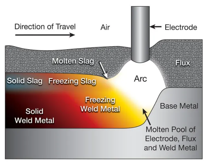
• In this process, a continuous bare electrode wire is used. The shielding is provided by external granular flux through hopper.
• Granular flux is provided just before the weld arc.
• granular flux completely provides protection from sparks, spatter, and radiation and hence safety glasses, gloves can be avoided.
some part of flux gets melted and forms a glassy layer.
• This layer and unfused flux results in slow goling rate and good weld
Arc welding with non consuble electrodes
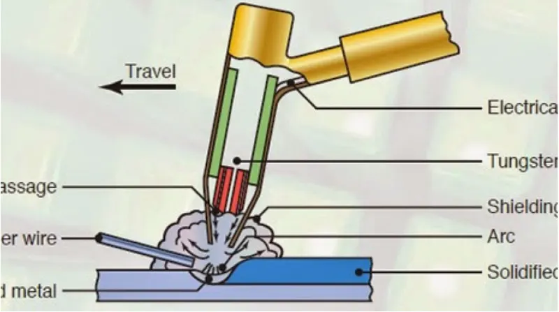
• It uses a non-consumable tungsten electrpde and shielding gas (inert gas) for shielding. Also called tungsten inert gas welding (TIG)
• Usage of filler wire is optional and is heated by are and not transferred across the arc.
Tungsten is a good electrode material due to its high melting point of 3400°C
Advantages
High quality welds, no weld spatter because no filler metal is transferred across the arc, and little postweld cleaning because no flux is used.
Plasma arc welding
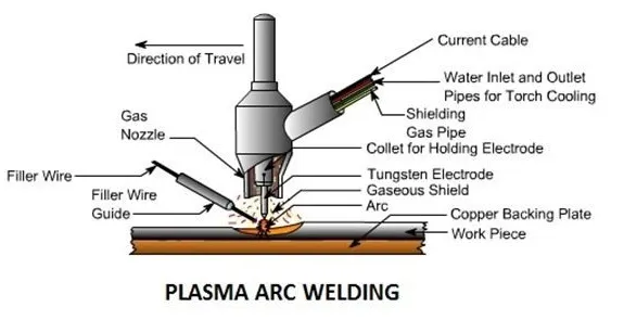
• It is a variety of gas tungsten arc welding in which a constricted plasma arc is used for welding
• In PAW, a tungsten electrode is kept in a nozzle that focuses a high velocity stream of inert gas into the region of the arc to form a
high velocity, intensely hot plasma arc stream.
• Temperatures in plasma arc welding reach 17,000 C. This is mainly due to the constriction of the arc. The input power is highly
concentrated to produce a plasma jet of smL diareter and very high power density.
The process can be used to weld almost any material, including tungsten.
Resistance welding
• Resistance welding (RI) is a fusion welding processes that uses a combined effect of heat and pressure to accomplish joining. This
heat is generated by clectrical resistance to current flow at the location to be welded.
• Weld nugget is generated by this process.
• R uses no shielding gases, flux, or filler metal
Electrodes that conduct electrical power to the process are non-consumable
Solid state welding processes
• In solid statc welding, joining of materials are performed with the help of heat and pressure or pressure alone.
A metallurgical bond is created with little or no melting of the base metals. To metallurgically bond two similar or dissimilar metals,
the two metals must be brought into intimate contact so that their atomic forces attract cach other.
• The two surfaces must be cleaned and free of oils, dirt, chemical films, gases etc. to permit atomic bonding.
Brazing
It is a joining process in which a filler metal is melted and distributed by capillary action between the faying (contact) surfaces of the
metal parts being joined.
• Base material does not melt in brazing, only the filler melts.
• In brazing, the filler metal has a melting temperature (liquids) above 450 C, but below the melting point (solidus) of base metals to
be joined.
Advantages of brazing
• Brazing can be used to join a large variety of dissimilar metals.
Pieces of different thickness can be casily joined by brazing
Thin-walled tubes & light gauge sheet metal assemblies not joinable by welding can be joined by brazing.
Complex & multi-component assemblies can be economically fabricated with the help of brazing.
• Inaccessible joint areas which could not be welded by gas metal or gas tungsten are spot or scam welding can be formed by brazing.
SOLDERING
Soldering is similar to brazing and can be defined as a joining process in which a filler metal with melting point (liquidus) not
exceeding 450'C is melted and distributed by capillary action between the faying surfaces of the metal parts being joined.
As in brazing, no melting of the base metals occurs, but the filler metal wets and combines with the base metal to form a
metallurgical bond.
• Filler metal, called Solder, is added to the joint, which distributes itsclf between the closcly fitting parts.
1. Spot Welding
Spot welding is a thermal process in which metals are joined by heat generated by resistance of electric current. In this work pieces(panels)are placed together under high pressure exerted by electrodes. When a large amount of current is passed through the panels , current melts the panelon that specific spot where electrodes are touching the panel and forms weld.
Mentioned area is known as die post of the gun.
In this gun actuator is parallel to the weld plane and and actuates about a pivot.
X type guns are used where accessibility is constraint.
C GUN :
C-type or straight action gun actuates perpendicular to the plane and in line with the weld.
Working Condition: That condition when both electrodes on gun are touching the panel while doing spot welding is called as Working Condition.
Semi opening condition or intermediate stroke: After completing one stroke, gun moves to next spot without opening completely is knownas intermediate stroke or semi opening. This opening may differ as per the requirement.
Full Stroke or Full opening : it is the maximum open condition of moving electrodes of the gun.
- Preferably Fixed electrode should be visible to the operator.
- Gun should have good reach-ability to all spots.
- As much as possible same gun should be used for maximum no. of spots.
- Tip wear out condition (preferably 5 mm) should be considered while designing the tool.
SPR- Self-piercing riveting is a cold mechanical fastening technique for joining of two or sheet metals or panels. For joining , the rivet is driven into the matel at a controlled force, piercing the panels, Then rivet radially expands into the bottom layer,due ti the shape of die, forming a mechanical interlock.
This process is quite helpful in joining of aluminium panels.
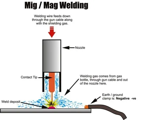
Metal inert gas welding or MIG Welding is based on the electric arc welding process where completion of an electric circuit between positive and negative poles creates an electric arc , which generates tremendous heat permitting the fusion welding of metals.
GLUE GUN :
Glue guns are used for metering of sealentso or adhesive bonds.
adhesive bonding and sealing are used for various applications in the modern automotive induastry.
3. Resistance Welding & its application in the automotive sector
Resistance welding is the joining of metals by applying pressure and passing current for a length of time through the metal area which is to be joined. The key advantage of resistance welding is that no other materials are needed to create the bond, which makes this process extremely cost effective.
There are several different forms of resistance welding (e.g. spot and seam, projection, flash, and upset welding) which differ primarily by the types and shapes of weld electrodes that are used to apply the pressure and conduct the current. The electrodes, typically manufactured from copper based alloys due to superior conductive properties, are cooled by water flowing through cavities inside the electrode and the other conductive tooling of the resistance welding machine.
Resistance welding machines are designed and built for a wide range of automotive, aerospace and industrial applications. Through automation, the action of these machines is highly controlled and repeatable allowing manufacturers to staff production readily.
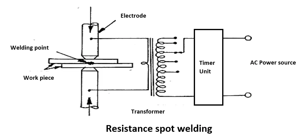
Resistance Welding Working Principle
The working principle of resistance welding is the generation of heat because of electric resistance. The resistance welding such as seam, spot, protection works on the same principle. Whenever the current flows through electric resistance, then heat will be generated. The same working principle can be used within the electric coil. The generated heat will depend on material’s resistance, applied current, conditions of a surface, applied the current time period
This heat generation takes place because of the energy conversion from electric to thermal. The resistance welding formula for heat generation is
H = I2RT
Where
- ‘H’ is a generated Heat, and the unit of heat is a joule
- ‘I’ is an electric current, and the unit of this is ampere
- ‘R’ is an electric resistance, and the unit of this is Ohm
- ‘T’ is the time of current flow, and the unit of this is second
The generated heat can be used to soften the edge metal to shape a tough weld joint with fusion. This method generates weld with no application of any flux, filler material, and shielding gases.
Types of Resistance Welding Applications:
-
Spot Welding and Seam Welding
- Resistance Spot Welding, like all Resistance Welding Processes, creates welds using heat generated by resistance to the flow of welding current between the faying surfaces, as well as force to push the workpieces together, applied over a defined period of time. Resistance Spot Welding uses the face geometries of the welding electrodes themselves to focus the welding current at the desired weld location, as well as to apply force to the workpieces. Once sufficient resistance is generated, the materials set down and combine, and a weld nugget is formed.
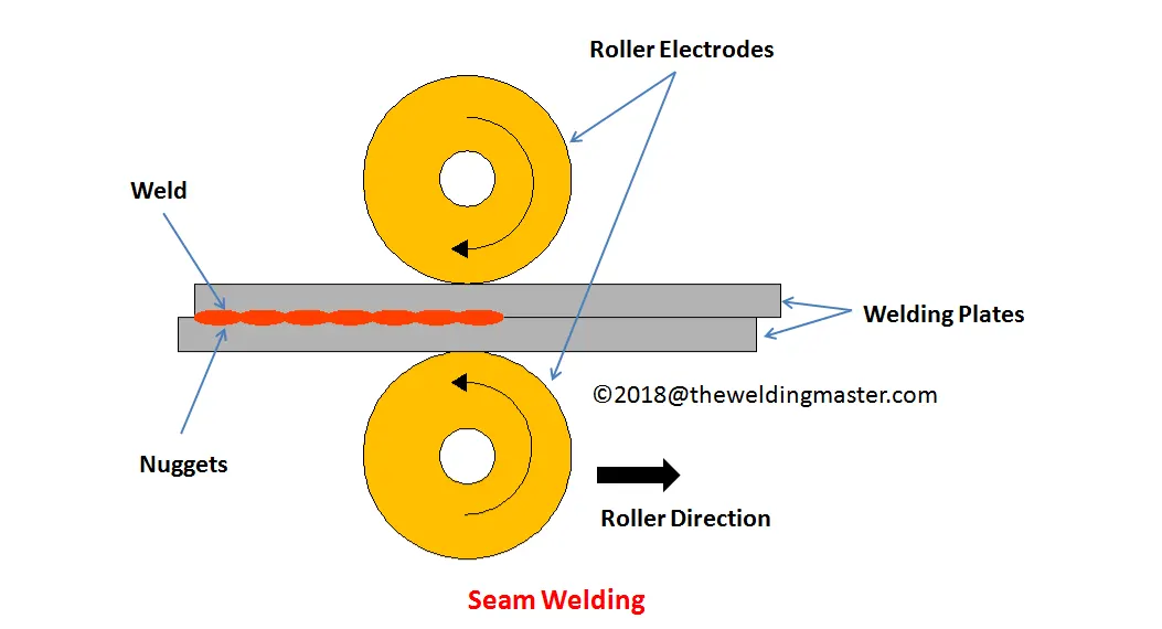
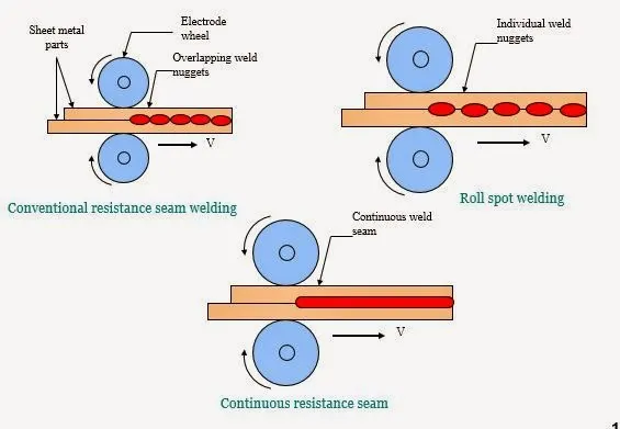
- Resistance Seam Welding is a subset of Resistance Spot Welding using wheel-shaped electrodes to deliver force and welding current to the parts. The difference is that the workpiece rolls between the wheel-shaped electrodes while weld current is applied. Depending on the particular weld current and weld time settings, the welds created may be overlapping, forming a complete welded seam, or may simply be individual spot welds at defined intervals.
-
Projection Welding
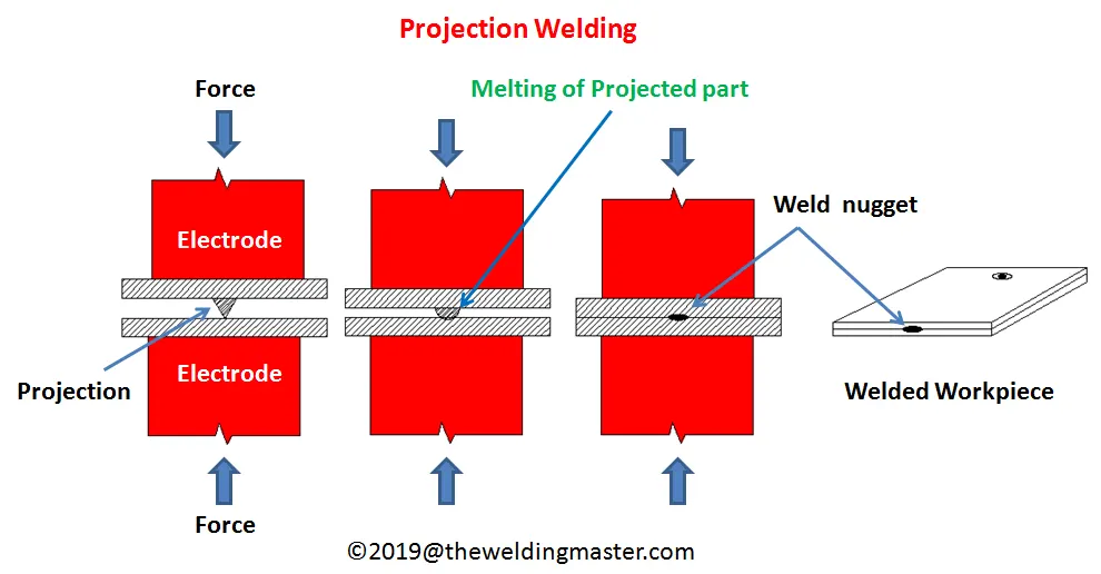
- Like other Resistance Welding Processes, Projection Welding uses heat generated by resistance to the flow of welding current, as well as force to push the workpieces together, applied over a defined period of time. Projection Welding localizes the welds at predetermined points by using projections, embossments or intersections, all of which focus heat generation at the point of contact. Once the weld current generates sufficient resistance at the point of contact, the projections collapse, forming the weld nugget.
- Solid Projections are often used when welding fasteners to parts. Embossments are often used when joining sheet or plate material. An example of Projection Welding using material Intersections is cross-wire welding. In this case the intersection of the wires themselves localizes heat generation, and therefore resistance. The wires set-down into one another, forming a weld nugget in the process.
-
Flash Welding
- Like other Resistance Welding Processes, Flash Welding uses heat generated by resistance to the flow of welding current, as well as force to push the workpieces together, applied over a defined period of time. Flash Welding is a Resistance Welding Process which generates resistance using flashing action. This action is created using very high current density at very small contact points between the workpieces. At a predetermined point after the flashing process has begun, force is applied to the workpiece, and they are moved together at a controlled rate. Rapid upset created by this force expels oxides and impurities from the weld.
-
Upset Welding
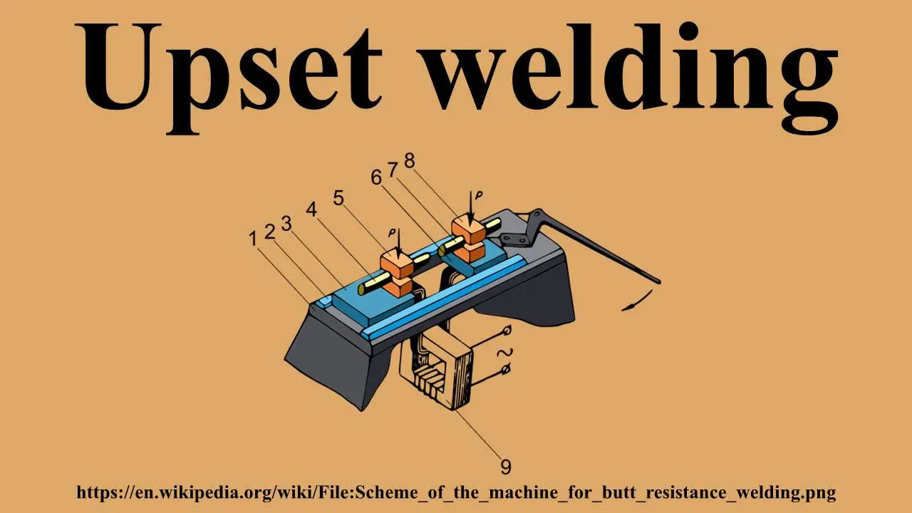
- Like other Resistance Welding Processes, Upset Welding uses heat generated by resistance to the flow of welding current, as well as force to push the workpieces together, applied over a defined period of time. While similar to Flash Welding, in Upset Welding the workpieces are already in firm contact with one another, so no flashing occurs. Pressure is applied before the current is started, and is maintained until the process is complete.
Features of Resistance Welding
(i) No flux such as solder is necessary. So, welded parts can be easily recycled.
(ii) Easy operation as only pressing buttons facilitates process automation and it does not require trained skills unlike arc welding and gas welding.
(iii) As this welding is performed efficiently in a short period of time, it is suited high-volume production of low-cost products.
(iv) Since welding is done in short time duration, it gives less heat-affected area on workpieces by resulting a beautiful appearance with less indentation.
(v) Electric facility is required in some cases due to use of large current. Optimum welding parameters must be figured out before actual welding since those parameters depend on material and thickness of parts to be welded. Welding condition setting must be prepared.
Advantages Of Resistance Welding :
1. Less skill is required to operate the resistance welding machine.
2.This type of welding is well suited for mass production as it gives a high production rate.
3.There is no need of using consumables such as brazing materials, solder or welding rods in this process except for the electrical power and a relatively smaller electrode wear.
4.Heating the workpiece is confined to a very small part which results less distortion.
5. It is possible to weld dissimilar metals as well as metal plates of different thickness.
6. It has a short process time.
7. It offers more safety to operator because of low voltage.
8. It produces clean and environmentally friendly weld.
9. A reliable electro-mechanical joint is formed.
10. The heat is localized, action is rapid and no filler metal is required.
11. The operation can be easily mechanized and automated due to the need of less skill.
Limitations of resistance Welding :
1. The resistance welding machine is highly complex with various elements such as a heavy transformer, electrodes and heavy conductors for carrying the high currents, electrode force applying mechanism such as a pneumatic cylinder and its supply, heavy machine structure to support the large forces and an expensive timing arrangement.
2. Certain resistance welding processes are limited only to lap joints.
3. Spot welds have low tensile and fatigue strength.
4. Equipment is not portable as it is heavy.
5. The cost of equipment is high.
Applications Of Resistance Welding :
1. Resistance welding is used in mass production for welding sheet metal, wire and tubes.
2. It is used in welding bars, boxes, cans, rods, pipes and frames metals of medium and high resistance materials such as steel, stainless steel, monei metal and silicon bronze which are easy to weld.
3. It is used in welding aircraft and automobile parts
4. It is used for making cutting tools.
5. It is used for making fuel tanks of cars, tractors etc.
6. It is used for making wire fabrics, grids, grills, mesh weld, containers etc.
4. fusion welding & types of fusion welding with its application in the automotive sector
Fusion welding is a process that uses heat to join or fuse two or more materials by heating them to melting point. The process may or may not require the use a filler material. External application of pressure is not required for fusion welding processes, except for resistance welding, where substantial contact pressure is required during welding for sound joining.
Fusion Welding Processes
Fusion welding processes can be grouped according to the source of the heat, for example, electric arc, gas, electrical resistance and high energy.
Advantages Of Fusion Welding:
1) Fusion Welding can be used to join dissimilar materials easily.
2) External filler material can be added easily.
3) No external pressure is needed.
4) Using this process, more than two components can be welded at a step.
Disadvantages Of Fusion Welding:
1) Due to intense heating and subsequent melting, many mechanical and metallurgical properties are affected.
2) Because of excessive heat input, high distortion takes place.
3) Noticeable heat affected zone exists around the weld bead due to excessive heat.
4) Welding two dissimilar metals is difficult specially if the metals have different melting points and coefficient of thermal expansion.
These processes include:
Arc Welding Processes - with the most common processes being:
Shielded Metal Arc Welding (SMAW), also known as manual metal arc welding (MMA or MMAW), flux shielded arc welding or stick welding. Suitable for welding ferrous and non-ferrous materials in all positions.
Advantages of SMAW
There are a number of advantages to SMAW welding, including:
- Lower equipment cost: Compared with other welding methods, SMAW equipment is simple and inexpensive.
- Lightweight and portable: SMAW equipment is easy to transport, making it a convenient method to use.
- Built-in shield: Since the flux-covered electrode generates its own protective gas, no additional exterior shielding gas is needed, so SMAW can be done outdoors.
- Versatile: SMAW can be used on a variety of different alloys and metals, as well as done in numerous positions.
Disadvantages of SMAW
While there are many advantages to the SMAW process, there are some disadvantages to keep in mind:
- Lower productivity rate: Unlike semi-automatic or automatic welding processes, SMAW is manual, which can translate into lower productivity.
- Less deposition: Deposition is the amount of welding material deposited per unit of time, and SMAW projects have a lowered amount in comparison with others.
- Spatter and slag cleanup: With SMAW, slag (a layer of byproduct) needs to be removed after welding. It can also produce more spatter, which can make it a messier process.
Metal Inert Gas Welding (MIG) and Metal Active Gas Welding (MAG), also known as Gas Metal Arc Welding (GMAW). MIG and MAG welding are the most common arc welding processes, in which an electric arc forms between a consumable wire electrode and the workpiece leading them to melt and join. Both use a shielding gas to protect the weld from airborne contaminants, or oxidation in the case of MIG welding.
What are the Advantages of MIG / MAG Welding?
- can be operated in several ways, including semi and fully automatically, including robotically
- allows for the fast production of high quality welds
- due to a lack of flux being used, there is no chance of slag being trapped in the weld metal
- is a versatile process that can be used to join a variety of metals and alloys
- MAG welding can be performed in all positions, making it one of the most widely-used welding processes.
What are the Disadvantages of MIG / MAG Welding?
- for vertical or overhead welding short circuit transfer is required. With no fast freezing flux, there is nothing to hold the fluid weld pool in position
- welding cannot be performed outdoors without enclosures as the welding gas needs to be protected from the wind
- with limited deoxidants available in the process, all rust must be removed from the workpiece before welding commences.
- flux cored arc welding (MAG welding with flux cored wires) may be more suitable for positional welding and outdoor applications. As with all arc processes, proper PPI must be worn and, in particular, eye protection
Tungsten Inert Gas Welding (TIG), also known as Gas Tungsten Arc Welding (GTAW). This arc process uses a non-consumable tungsten electrode to create the arc between the electrode and the base plate. An inert shielding gas is used to protect from oxidation or other atmospheric contamination. This process can be used autogenously on thin parts, but will require the addition of a wire, rod, or consumable to be added for thicker parts.
applications
- The most important applications for TIG welding are pipeline and pipe welding. It is, however, used in many industries, such as aviation and aerospace and sheet metal industries when welding particularly thin materials and special materials such as titanium.
- TIG welding is suitable for both manual and mechanized welding as well as for using welding robots.
Plasma Arc Welding is a liquid state welding process. Here in this paper, you are going to learn the Definition of Plasma Arc Welding, Components and Working Principle of the Machine, along with the Applications, Advantages, and Disadvantages of this Welding. So now let’s get started with the definition of PAW!
What is Plasma Arc Welding?
Plasma Arc Welding (PAW) is a liquid state welding process in which the metal to metal joint forms in a molten state with the help of hot ionized gases known as Plasma. These hot ionized gases used to heat the work plates, and the joint is created due to fusion.
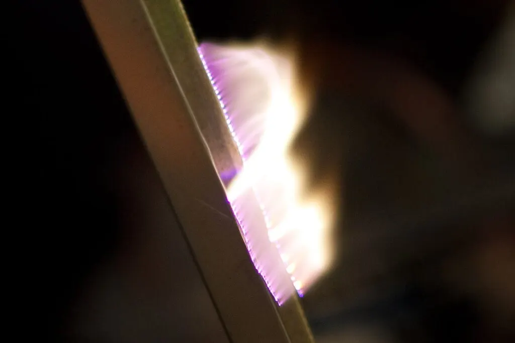
Construction of the Machine:
The Plasma Arc Welding setup consists of the following components:
- Power Supply
- Plasma Welding Torch
- Water re-circulator
- Tungsten Electrode
- Shielding Gas
- Plasma Gas
- Torch Accessory Kit (Tips, ceramics, collets, electrodes set-up gages)
- Filler Material
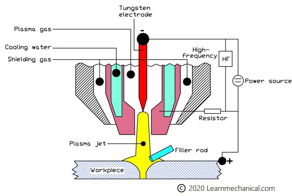
Let me give you the brief overview of each components.
Power Supply:
The plasma arc welding process needed a high power DC supply to generate the electric spark in between the tungsten electrode and welding plates.
This welding can weld at a low 2 amp and the maximum current which it can handle is about 300 amp. It needs about 80 volts for proper working.
The power source consists of a transformer, rectifier and control console.
Plasma Welding Torch:
This is the most important part of the plasma welding process.
This torch is quite similar as used in TIG welding.
PAW torches are water-cooled because the arc is contained inside the torch which produces high heat, so a water jacket is provided outside the torch.
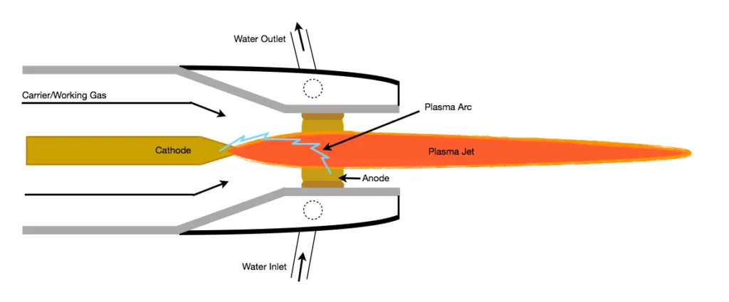
Water Re-circulator:
This mechanism is used to cool the welding torch by the continuous flow of water outside of the welding torch.
Tungsten Electrode:
In this machine, we use a no-consumable tungsten electrode. As we know tungsten can withstand very high temperature.
Shielding Gas:
In this welding process, we use two inert gases. We need to maintain a low pressure to avoid the turbulence while welding due to this low-pressure gases welding shield is formed weekly, that’s why we need to charge another inert gas through the outer portion of the welding force in high flow rate, to make the weld shield sustainable.
The inert gases which are used in this process can helium, argon, and also hydrogen as per the need, and it is totally depends on the temperature.
Plasma Gas:
It is an ionized hot gas composed of nearly the same numbers of electrons and ions. It has sufficient energy to free electrons from molecules, atoms, and electron to synchronise.
It is the main energy source of this welding.
Torch Accessory Kit:
These kits are used to expanding the performance of the welding torch.
Filler Material:
In Plasma welding there is no filler material is used. If the filler material is used, then it is directly fed into the weld zone.
Working Principle of Plasma Arc Welding Machining:
This is an arc welding process, a concentrated plasma arc is produced with the help of high-frequency unit of the machine and directed towards the weld area.
The plasma starts between the tungsten electrode and the orifice by a low current pilot arc. The plasma arc welding is concentrated because it is forced through a relatively small orifice or nozzle to increase its pressure, temperature and heat.
Because of the above characteristic, the arc will now become very stable, improved in shape and heat transfer rate.
The temperature of the arc is as high as 33,000°C due to this phenomenon heat the nozzle is surrounded by a water cooling system to avoid wear out of the nozzle due to heat.
Operating currents usually are less than 100 amp. This makes Plasma Welding different from other types of welding.
When filler metal is used it is fed into the arc as is done in Gas Tungsten-arc Welding. Arc and weld-zone shielding are supplied by means of an outer shielding ring and the use of inert gases like argon, helium or mixtures.
You may watch this video for a better understanding of the Plasma Arc Welding Process:
Advantages of PAW:
The advantages of Plasma Arc Welding are following:
- Torch design allows better control of the arc.
- This method provides more freedom to observe and control the weld.
- The higher the heat concentration and plasma jet allow faster travel speeds.
- The high temperature and high heat concentration of plasma allow the keyhole effect.
- This provides complete penetration with the single-pass welding of many joints.
- The heat-affected zone is smaller compared to GTAW (Gas tungsten arc welding).
- It uses less current input as compared to another welding process.
Disadvantages of PAW:
The disadvantages of Plasma Arc welding are:
- It produces wider welds and heat-affected zones compare to LBW and EBW.
- Plasma welding equipment is very costly. Hence it will have a higher startup cost.
- It requires training and specialization to perform plasma welding.
- It produces ultraviolet and infrared radiation.
- The method produces higher noise on the order of about 100dB.
- The torch is bulky and hence manual welding is a bit difficult and requires training as mentioned.
Applications of PAW:
The application of Plasma Arc welding are:
- This welding is used in marine and aerospace industries.
- This is used to weld pipes and tubes of stainless steel or titanium.
- It is mostly used in electronic industries.
- Also, this is used to repair tools, die, and mould.
- This is used for welding or coating on a turbine blade.
So this is all about Plasma Arc Welding Machining, I hope you enjoyed this article. I also wrote articles on some other welding processes do check out those too. And moreover do not forget to share the article on your favourite social platform.
Submerged Arc Welding (SAW). This frequently-used arc welding process uses a continuously-fed consumable electrode and a blanket of fusible flux which becomes conductive when molten and provides a current path between the workpiece and the electrode. The flux also prevents spatter and sparks while suppressing ultraviolet radiation and fumes.
Advantages
The advantages of Submerged Arc Welding include the following.
- This submerged arc welding process has high (45kg/h) deposit rate.
- In automatic applications.
- Very small welding smoke can be observed.
- No edge training is required.
- This method is used in indoor, and outdoor.
- No chance of weld sprinkles because it is submerged within flux blanket.
Disadvantages
The disadvantages of Submerged Arc Welding include the following
- The process is incomplete to some particular metals.
- The application is imperfect to direct seams vessels, and pipes.
- The flux usage is hard.
- A health problem can be occurred due to the flux.
- Slag elimination is desirable after welding.
Submerged Arc Welding Applications
The applications of Submerged Arc Welding include the following
- The Submerged Arc Welding can be used to weld pressure vessels like boilers.
- A lot of structural outlines, pipes, earth moving tools, shipbuilding, railroad construction, and locomotives.
- This type of welding can be used to repair machine parts.
Flux Cored Arc Welding (FCAW). Developed as an alternative to SMAW, this process uses a continuously fed consumable electrode with a flux and a constant voltage or constant current power supply. Sometimes using a shielding gas this process can also just use the flux to provide protection from the atmosphere.
Working of FCAW
The working of flux cored arc welding FCAW is less complex and can be easily understood. Unlike other arc welding process that uses AC or DC power supply, FCAW supplies power only from DC electric arc to the welding gun. The arc is produce when the gun is struck between the continuously fed consumable filler wire and the workpiece. It create the weld pool and bond when the pool solidifies.
Advantages
Below are the advantages of FCAW:
- It has different ways of supplying shielding gas
- It may be applied to all welding position
- Shielding gas is not needed for some its wires are suitable in windy conditions
- It has high deposition rate
- Chances of porosity are very low
- Less cleaning of base metal
Disadvantages
Despite the great benefits of FCAW, some disadvantages still occur. Below are the limitations of flux cored arc welding in their various applications.
- It produces slag, which must be removed after welding
- It produces more smoke which is hazardous to the welder
- Cost of applied wire
- It Is complex and more expensive
- It produces more spatter
Gas Welding Processes - the most common process being:
Oxy-Fuel Welding, also known as Oxyacetylene Welding but commonly called gas welding, this process uses a hand-held torch or blow pipe and a mixture of oxygen and acetylene which combusts to create a flame.
Resistance Welding Processes
Resistance Spot Welding. This fast welding process delivers heat between two electrodes according to the material properties and thickness of the workpieces. The welding current is concentrated to a small spot as the workpieces are simultaneously clamped together.
Resistance Seam Welding. This variant of spot welding produces a series of overlapping nuggets of a continuous joint by replacing conventional spot welding electrodes with wheels which rotate as the workpieces are fed between them.
High Energy Welding Processes - with the main ones being:
Electron Beam Welding (EBW). This fusion process is performed under vacuum conditions, using a beam of high velocity electrons to melt the workpieces as the electrons generate heat upon penetration into the material. Welds are often deep and narrow.
Electron beam welding couplings
Electron beam welding is used to melt and join base materials. Because the welding is characterized by a small spot with minimal heat effects, couplings with no gaps are ideal. However, when welding at a max. penetration depth of 3 to 5 mm, gaps of up to 0.1 mm are generally allowed. Deeper penetrations allow for a larger gap threshold. At a penetration depth of 50 mm, welding is possible even with a 3 mm gap by using filler material (welding wire).
- Typical weld couplings possible with electron beam welding
(EB = electron beam) -
-
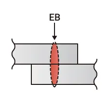
Lap
-
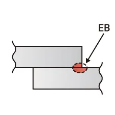
Lap fillet
-
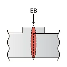
Overlapped butt
-
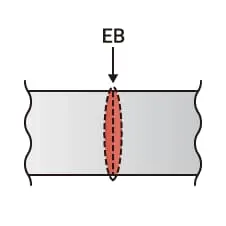
I-shaped butt
-
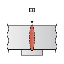
I-shaped butt (with backing)
-
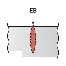
I-shaped butt (stepped)
-
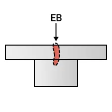
T-shaped through-hole
-
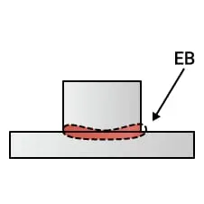
T-shaped fillet
-
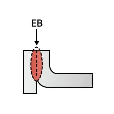
Edge
-
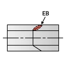
Diagonal butt
-
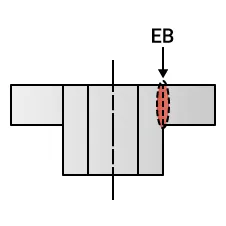
Tube
-
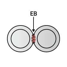
Pipe cutting line
-
application :
The full range of electron beam welded fabrications is incredibly diverse - after all, not many welding techniques can weld (say) steel that is 0.1mm thick, or at the other extreme 300mm thick in a single pass! Some examples of electron beam welded products are given below:
- Bi-metal saw blades are produced in large numbers by electron beam welding. The high speed steel required for the cutting teeth is electron beam welded in a narrow strip to the main part of the blade, which is in low carbon steel. Material costs are reduced, and the bi-metal blade is considerably more flexible and thus less prone to breakage. This results in an improved product, both in terms of cost and performance.
- Transmission assemblies are frequently fabricated by electron beam welding. Complex parts can be fabricated with great savings in machining and materials. The parts can be finish-machined and hardened prior to welding, which is the final operation. This example illustrates the ability of electron beam welding to restrict distortion to a minimal level, thus allowing easy fabrication of otherwise difficult or even impossible components.
- Aerospace components in titanium alloys are fabricated by electron beam welding. Again low distortion means intricate components can be accurately joined. Due to the clean vacuum welding environment, there is no risk of oxygen pick-up and consequent weld embrittlement when electron beam welding these titanium alloys.
Being a vacuum based process, electron beam welding is ideal for sealing of pre-evacuated housings and electrical components. Despite the pump down time needed, small components can be welded with a cycle time of typically 10s or less.
The above examples go some way towards illustrating the diverse range of materials and component types that are electron beam welded. However, the applications of the technique are wider ranging still.
Besides the ability to weld thick material to thin material, electron beam welding also allows joining of dissimilar metals, i.e. those with different melting points and thermal conductivities. Some combinations which are unweldable by other processes are thus readily electron beam welded.
The applications detailed here require welding powers of a few hundreds of watts to tens of kW. Electron beam welding equipment is available with powers of over 100kW.
Laser Beam Welding (LBW). Often used in high volume applications, LBW uses a laser beam to provide a concentrated heat source with high levels of accuracy which can be used to join metal and polymers.
Working Principle of Laser Beam Welding
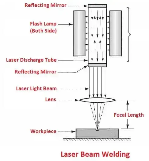
The laser beam welding works on the principle that when the electrons of an atom are excited by receiving some energy. And then after some time when it returns to its ground state, it emits a photon of light.
The concentration of this emitted photon is increased by the excited emission of radiation and we get high energy focused laser beam. The light amplification by stimulated emission of radiation is named as a laser
Working of Laser Beam Welding
Initially, the welding machine is setup (between the two metal pieces to join) at the desired location. Later setup, a high voltage power supply is applied to the laser machine to perform an operation.
The lens is used to focus the laser into the area where welding is required. CAM is used to control the speed of the laser and workpiece table during the welding process.
Read also: Types of Welding
It starts the machine’s flash lamp and it emits light photons. The energy of light photons is absorbed by the atoms of ruby crystals and electrons are excited to their higher energy levels. When they return to their low energy state or ground state they emit a photon of light.
This light photon again stimulates the electrons of the atom and produces two photons. This process continues and we get a focused laser beam that is used on the desired location for welding multiple pieces together.
Equipment of Laser Beam Welding
Following are the main equipment of laser beam welding:
- Laser Machine
- CAM (Computer-aided manufacturing)
- CAD (Computer-aided design)
- Shielding gas
- Power source
1. Laser Machine
A laser beam machine is a machine that is used to generate lasers for welding. The main parts of the laser machine are described below.
2. CAM (Computer-aided Manufacturing)
It is a computer-aided manufacturing (CAM) in which a laser machine is combined with a computer to perform the welding process. All control actions are performed during the welding process by CAM. This speeds up the welding process to a great extent.
3. CAD (Computer-aided Design)
The CAD stands for Computer-aided Design. It is a software in which we can design the job for welding. Here the computer is used to design the workpiece and how welding is done on it.
4. Shielding Gas
Shielding gas may be used during the welding process to prevent W/P from oxidizing.
5. Power Source
A high voltage power source is used to the laser machine to produce a laser beam.
Types of Laser Used in the Laser Beam Welding
Following are the main types of laser used in these types of welding:
- Gas laser
- Solid-state laser
- Fibre laser
1. Gas Laser
These types of laser use a mixture of gases for the production of lasers. It contains gases such as nitrogen, helium, and CO2 are used as the lasing medium.
2. Solid-state Laser
In these types of laser use many solids in synthetic ruby crystals (chromium in aluminium oxide), neodymium in glass (Nd: glass) and neodymium in yttrium aluminium garnet (Nd-YAG, the most commonly used).
3. Fibre Laser
The lasing medium in this type of laser is the optical fibre.
Advantages and Disadvantages of Laser Beam Welding
Following are the advantages:
- Easily automated process.
- Controllable process parameters.
- The very narrow weld may be obtained.
- High quality of the weld structure.
- Very small heat-affected zone.
- Dissimilar materials may be welded.
- Very small delicate workpieces may be welded.
- The vacuum is not required.
- Low distortion of the workpiece.
Following are the disadvantages:
- The initial cost is high. The equipment applied in LBW has a high cost.
- The maintenance cost of LBM is high.
- Due to the rapid cooling, fractures can occur in some metals.
- High skilled labours are required to perform LBW.
- The welding thickness is restricted to 19 mm.
- The energy conversion efficiency in LBW is extremely low. It is usually below than 10%.
Applications of Laser Beam Welding Process
- It is prominent in the automotive industry. So, It is used in the area where large volume production is required.
- It is employed for high precision welds. As it does not use any electrode, the final weld will be light but strong.
- The laser welding is also frequently used in making of jewellery.
- However, laser beam welding is used in medical industries to hold metals together on a small scale.
5. 3-2-1 principle
What is it?
A fundamental concern in metalworking is locating the part to be machined, punched, bent, or stamped relative to the work platform (fixture). For example, a CNC machine tool starts its process at a specific point relative to the fixture and proceeds from there. Hence, the accuracy with which a part is machined is quite dependent on the accuracy with which it is positioned in the fixture.
Accurate locating of not just one part, but each and every part that is loaded into the fixture is crucial. Any variation in part location on the fixture adds to the dimensional tolerance that must be assigned to the finished parts.
Additionally, the method of supporting and securing the part in the fixture affects not only dimensional tolerances, but surface finishes as well. This is true because improper supporting or clamping can temporarily or permanently deform the part. Hence, techniques for supporting and clamping must be considered together with the method of locating in order to assure repeatability from part-to-part.
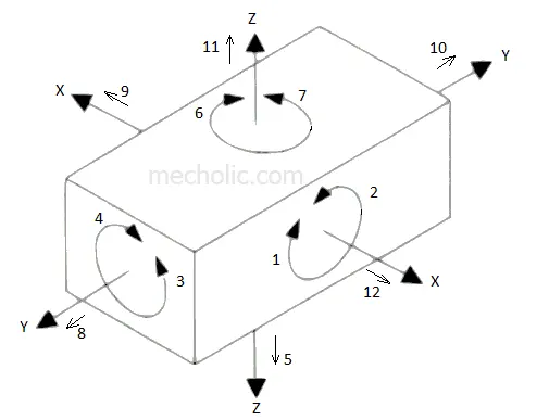
Locating of a part to be machined is a three-step process:
1. Supporting
2. Locating (positioning)
3. Holding (clamping)
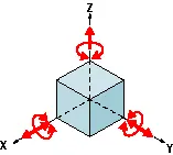
The Locating Process: Degrees of Freedom
In order to completely specify the position in space of a three-dimensional
object (such as the cube that’s shown), we refer to six coordinates:
- Translational position along the X-axis
- Translational position along the Y-axis
- Translational position along the Z-axis
- Rotational position about the X-axis
- Rotational position about the Y-axis
- Rotational position about the Z-axis
These six coordinates are known as the six degrees of freedom of a three-dimensional object. As the double-headed arrows indicate, the translational and rotational positions can vary in either direction with respect to each of the three axes.
To completely prevent movement, all six degrees of freedom must be restricted.
The Locating Process: 3-2-1 Method
We have two objectives when mounting a part in a fixture for machining:
1. Accurately position the part at the desired coordinates.
2. Restrict all six degrees of freedom so that the part cannot move.
A widely used method of accomplishing these two objectives uses the 3-2-1 principle, so-called because it entails three steps that employ three, then two, then one fixed points of known location. Since that adds up to six fixed points, it’s also known as the six point method.
In the three steps of the 3-2-1 method, three mutually perpendicular planes, called datum planes, are introduced, one at each step. These three planes define the workpiece position, and together with opposing clamping forces fully constrain the part. Let’s take a look at the details of the 3-2-1 method.
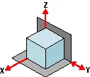
First Plane
Geometry tells us that three points are required to define a plane. This is the "3" in 3-2-1. So, three specific points are used to define the first plane. Fewer than three points cannot define a plane, and in the real world dimensional tolerances mean that four or more points will not be coplanar. A real-world, less than ideally perfect part placed on four or more reference points will, in fact, rest on only three of the points due to its less than perfect surface. Different parts may rest on different combinations of three points, resulting in variation between finished parts. A stool can be used to illustrate this concept. A two-legged stool would certainly be unstable. A three-legged stool sits rock-solid. A four-legged stool is often found to rock. In the illustration, a three dimensional part, represented by a cube, is placed on a datum plane defined by three support points. The part’s six degrees of freedom have now been reduced to three. It can still move along the X or Y axes, and it can still be rotated about the Z axis. (The part cannot move along the Z axis because it is held against the plane by clamping force.
TIPS
- Use the largest surface of the part for the first ("primary") reference plane.
- Position the three support points as far apart as possible.
- If more than three support points are required to prevent deflection, make the additional points adjustable.
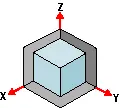
Second Plane
A second plane, if it is perpendicular to the first, can be defined by two points, the "2" in 3-2-1. The part is now constrained to one degree of freedom: movement along the Y axis. (The part cannot move along the X or Z axes because it is held against the planes by clamping force.)
TIPS
- Use the largest surface of the part for the first ("primary") reference plane.
- Position the three support points as far apart as possible.
- If more than three support points are required to prevent deflection, make the additional points adjustable.
Third Plane
A third plane, if it is perpendicular to both of the first two planes, can be defined by one point, the "1" in 3-2-1. The part is now entirely constrained. It cannot move along or rotate about the X, Y, or Z axes. (Remember that the part is held against each of the three planes by clamping force.)
TIPS
- If more than one support point is required to prevent deflection, make the additional points adjustable.
Machined is Best
It’s best if the workpiece surfaces intended to contact the support points are machined. Cast surfaces are usable, but then tend to create tolerance problems. Machined holes are the number one choice. Two machined holes can be used to eliminate all but one degree of freedom.
Repeatability
Repeatability
Repeatability is a paramount concern. It means that each part should be nearly identical to each other part coming off the same fixture. "Nearly identical" actually has a specific, quantifiable meaning: key dimensions of all parts produced on the same fixture must fall within defined tolerances.
In order to stay within tolerances, it’s best if the workpiece surfaces intended to contact the support points are machined. Cast surfaces are usable, but they tend to create tolerance problems. Machined holes are the number one choice, because two machined holes can be used to eliminate all but one degree of freedom.
The next best feature to use for consistent locating is machined surfaces at right angles. The "machined surface" desired here can simply be a tab or small flat specifically included for locating purposes.
Repeatability is achieved through application of the 3-2-1 method to the three aspects of the locating process:
1. Supporting
2. Locating (positioning)
3. Holding
Supporting
- The part is supported from "below" with reference to the Z axis. (Introduction of the first reference plane.)
- Gravity positions the part against the support locator.
- Provide adjustable auxiliary support points as needed to prevent deflection.
- Vertical location with respect to the fixture is now established
- The part is positioned horizontally, in the X-Y plane. (Introduction of the second and third reference planes.)
Holding
- The part is clamped against fixed locators. Therefore, a known and unvarying position of the part is maintained with respect to the X, Y, and Z axes.
- One strap clamp or clamp arm will restrict the workpiece in three dimensions due to friction between the workpiece and clamp. However, friction alone may not be enough to prevent the workpiece from moving during machining.
- Cutting forces will not move a properly supported and clamped part.
Locating
- The part is positioned horizontally, in the X-Y plane. (Introduction of the second and third reference planes).
Summary: Clamping Rules of Thumb
- Define three reference planes on the workpiece and fixture.
- Provide one opposing clamping force opposite each plane to restrict movement.
- When in doubt, rely on additional cylinders to take up uncertainty.
Mechanical and Hydraulic Workholding
Holding a workpiece in place can be done in a variety of different manners. For those just getting started or even those with vast experience in manufacturing, choosing the right method is not always easy. What are the benefits of each method? What are the disadvantages? How do I get started? What types of components do I need? How do they work together? How do I know it is going to work? The next issue of Enerpac University will answer these questions and many more as we present a guide to mechanical and hydraulic workholding, and even offer a combination of the two that incorporates the best features of both
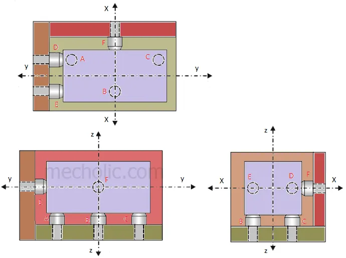
6. Body coordinate system
The body coordinate system is widely used in the automotive industries for drawing body parts, products, and process design.
A coordinate system is a reference system consisting of a set of points, lines, and surfaces used to define the position of points in
space in either two or three dimensions.
To represent the position of BIW car parts, welding fixture and its unit assemblies with its individual parts (e.g. Mylar(the parts which
are in contact with panel)) in 2D drawings, their respective positions are shown with reference to (X=0. Y=O. Z=0)positions. In short, it
shows in 2D XY, YZ, or XZ coordinate position of BIW welding fixture parts or assemblies with reference to origin X=0, Y=0, Z=0
Let us consider a situation if an individual fixture designer starts designing a part or panel on their default axes system then it will be
difficult to assembly or position the part with respect to each other. So in order to avoid this all the designer starts designing with
respect to car axes system (which is generally at the center of the front axle)
We consider a case where the axes system is from the front end of the car
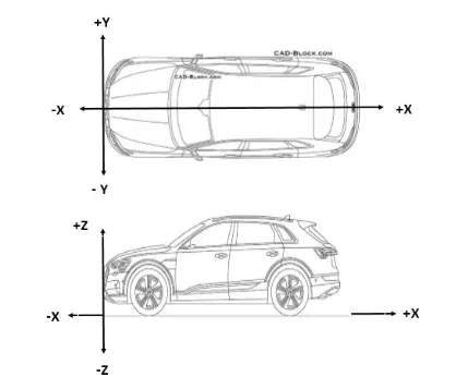
X - Longitudinal direction [Front 'o' Line -FoL]
Y - Transverse direction [Center o' Line - CoL]
Z- Vertical direction [Bottom o Line - BoL]
The origin of the body coordinate system OX is defined at the front center of the car and it indicates the length of the car. The
OZ [bottom © Line] is defined at the bottom of the car in the plane where the tire of the vehicle touches the ground and it in
height of the car. Finally, the origin of the OY coordinate lies in the center of the car and it indicates the width.
7. Elaborate Body plane system & its essentials
Body planes are reference planes in an automotive car. These planes are used to define the GD&T of all car parts in an automotive doma
Body planes are three mutually perpendicular imaginary planes. These are generally considered to be present at the driver position or
sometimes at the engine location or at the front end of the car
The core element of any car is the body structure. The car body connects all the different
components; it houses the drive train and most importantly carries and protects passengers
and cargo. The body structure needs to be rigid to support weight and stress and to securely
tie together all the components. Furthermore, it must resist and soften the impact of a crash to
safely protect the occupants. In addition, it needs to be as light as possible to optimize fuel
economy and performance. Over the years, various designs have been used and each of
them has its benefits and drawbacks.
The measurements from the body planes to the body parts are called body line dimensions
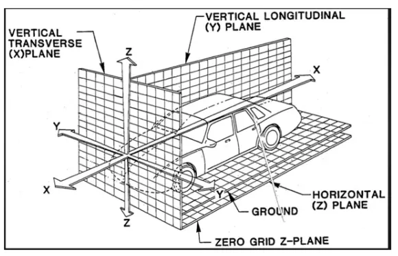
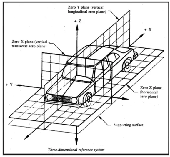
The need of the body planes are as below
1. It defines the exact position of each part of the car with respect to a fixed origin.
2. It ensures flawless design for assembly,
3. It assists in the location of different parts in the vehicle
4. It creates a standard system
5. It is very helpful in Quality checks.