Week 2:- BiW Fixture Basics Challenge
Q-1 What is the process of project execution activity?
1.RFQ received
It is the first stage of the project. RFQ stands for request for quotation.The customer specifies the requirement and specification of the project in the form of data or a document. The technical offer, commercial offer and the timeline for the completion of the project are also specified by the customer.
2.Spec discussion meeting
After receivingthe RFQ from the customer, the documents regarding the technical offer, commercial offer, and timeline are prepared. The timeline includes the time required for design, Simulation, manufacturing till the installation of the product to the customer.
3.0ffer submission
The prepared document is then submitted to the customer to work on it, to check whether the requirements are met and the time period mentioned is acceptable and feasible for them.
4.LOl/PO receipt
The documents which are submitted will be studied by the customer. The customer also gets documents from other firms, compares them, and select the best offer that would suit their requirement. Once the customer chooses the best offer the purchase order is generated and the work will be started. Meanwhile,the project team does a little work on the project so thatthey would adhere to the timeline once the PO is given to them.
5.BOM
BOM stands for Bill of material which is prepared for the project for the parts that are required for the project like motors, cylinders, etc.
6.Design Concept Preparation.
The data is received like the 3d data from the car panel and 2d drawi ngs from the customer along with the LOI/PO regardi ng the req uirements.Using this data, the design concepts are preparedto fullfill the customer's needs.
7.Customer approval
After the design concept is prepared from the data provided by the customer. The designed concept is sent to the customer for approval. The customer checks whether the submitted design adheres with the technical off er or not. If it is satisf ied then the customer approves the design and if not few changes will be made in the design and later will be approved.
8.Detailing and Drawing Release
Once the final approval is given by the customer. after making the required changes, the design drawings are released with all the necessary details like dimensions, tolerances, etc.
9.Manufacturing I BOM Ordering
The released drawing is submitted to the manufactu ring team and they start manuf acturing the parts like the ri ser, Mylar, etc, and the parts like the motors, sensor.
10.Mechanical /Electrical Assembly
The ordered parts undergo prior quality control checks and also they are checked for the required specifications. Once the quality check is done the mechanical and electrical parts are assembled as per the design.
11.Quality Inspection
After the assembly again the quality inspection is done to check whether the dimensions are as per the design data,the coordinates, and accuracy.The relative dimensions between the two pins are also checked. CMM is used for inspection purposes.
12.lnternal Trial and Testing
Once the assembly is quality approved, internal trial and testing are done where the assembly is put into the fixture and checked for the position of the pins and whether the clamping is proper or not. Operations like welding, Loading, and unloading are also tested during the trial.
13.0nline Trial
In the Online trial,everything is done using the control panel in an automated mode and checked whether the sequence of operation is as per the specification.The customer approves the part after the online trial.
14.Packaging and Dispatch
Once the customer approves after the online trial. He asks the team to send the part for installation.The fixture is packed and proper packaging is ensured so that there is damage. during the transportation of the fixture both
Q-2.Types of joinin processes
joining process is a connection of two metals of same materials or different into one Mechanical joining includes bolting, riveting, caulking, shrink fitting, and folding, all of which join workpieces by using mechanical energy.Metallurgical joining includes fusion welding, pressure welding and brazing/soldering which use different energies.There are also methods of chemical joining that use adhesives.Every joining method has advantages and disadvantages. To ensure efficient joining, you need to select the right method according to the materials and joining conditions. these are of three types they are
- metallurgical joining
- mechanical joining
- Chemical joining
Metallurgical joining process is mainly a combinig process of two metals by heating and melting process and thre are different process are involved in it but instead of all we are popularly using three methods called
- welding
- soldering
- brazing
WELDING
Welding is a fabrication process that joins materials, usually metals or thermoplastics, by using high heat to melt the parts together and allowing them to cool, causing fusion. Welding is distinct from lower temperature metal-joining techniques such as brazing and soldering, which do not melt the base metal.
solid state welding(friction welding)- a solid state welding is involved in joining of the two metals through friction process means a continues rubbing is takes place between two metals to join them by producing heat between them.
principle
Friction welding works on basic principle of friction. In this welding process, the friction is used to generate heat at the interference surface. This heat is further used to join two work pieces by applying external pressure at the surface of work piece. In this welding process, the friction is applied until the plastic forming temperature is achieved. It is normally 900-1300 degree centigrade for steel. After this heating phase, a uniformly increasing pressure force applied until the both metal work pieces makes a permanent joint. This joint is created due to thermo mechanical treatment at the contact surface.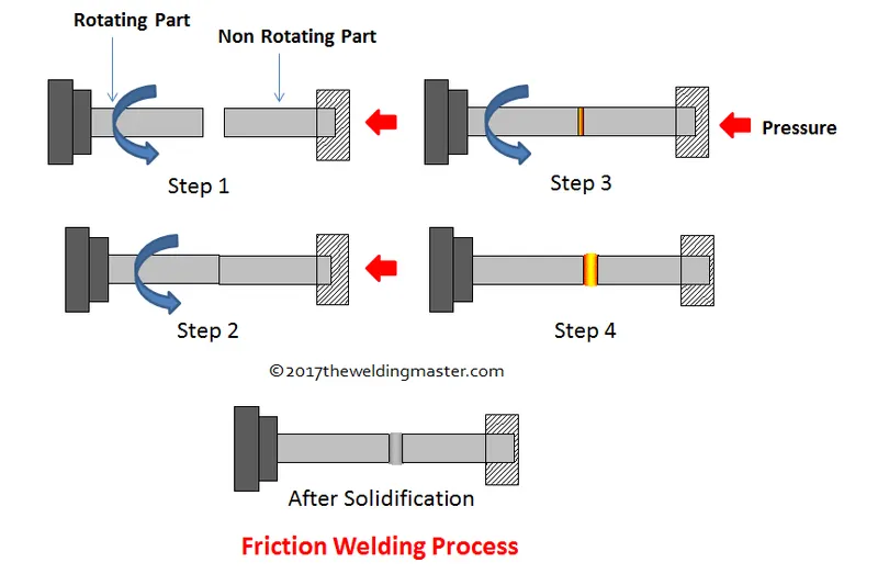
liquid welding(fusion welding)
From the definition, fusion welding joins edges of different materials by heating them to a melting point. Sometimes, a filler material is necessary if there are gaps in the joint you are making. The materials will undergo many phase transitions because the heating process creates a heat effected zone on the material(s).
Fusion welding takes place when the molten base materials join with molten fillers. The heat that melts the materials can be applied to the joining zone or developed externally at the intended weld point. For instance, you can pass current via an electrical contact resistance between the edges of the materials you are welding together to develop the heat you need.
SOLDERING
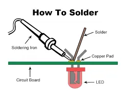
Soldering is a joining process used to join different types of metals together by melting solder. Solder is a metal alloy usually made of tin and lead which is melted using a hot iron. The iron is heated to temperatures above 600 degrees fahrenheit which then cools to create a strong electrical bond.
- Soft soldering (90 °C - 450 °C) - This process has the lowest filler metal melting point of all the soldering types at less than around 400°C these filler metals are usually alloys, often containing lead with liquidus temperatures under 350°C. Because of the low temperatures used in soft soldering it thermally stresses components the least but does not make strong joints and is then therefore unsuitable for mechanical load-bearing applications. It is also not suited for high temperature use as this type of solder loses strength and melts.
- Hard (silver) soldering (>450 °C) – Brass or silver is the bonding metal used in this process, and requires a blowtorch to achieve the temperatures at which the solder metals.
- Brazing (>450 °C) – This type of soldering uses a metal with a much higher melting point than those used in hard and soft soldering. However, similarly to hard soldering, the metal being bonded is heated as opposed to being melted. Once both the materials are heated sufficiently, you can then place the soldering metal between them which melts and acts as a bonding agent.
BRAZING
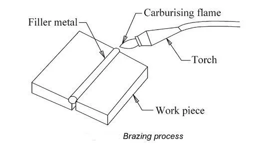
it is a classification of the soldering process which takes place at >450 degree centigrade temperature.Brazing is a joining process traditionally applied to metals (but also to ceramics) in which molten filler metal (the braze alloy) flows into the joint.
The filler metal, while heated slightly above melting point, is protected by a suitable atmosphere which is often a flux. The molten filler metal cools to join the workpieces together providing a strong join between similar or dissimilar metals.
MECHANICAL JOINING
a mechanica jonig involves in joining of two same or different materials by any mechanica force or any mehanism like bending,shearing,compressing,or tensile force etc.. and in this mainly we are involves three modes they are
- Riviting
- Hemming
- Bolting
RIVITING
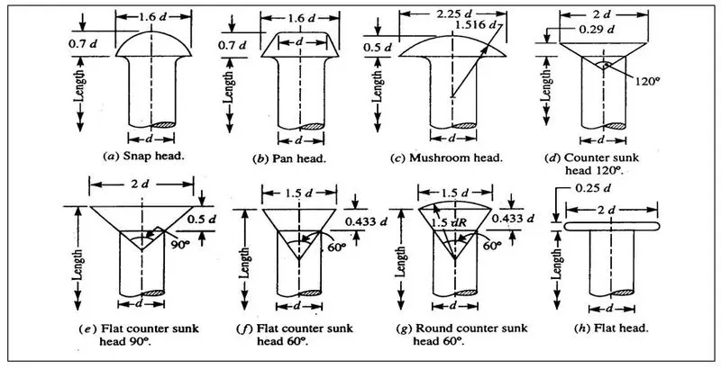
Riveting is a forging process that may be used power to fix the parts together by engrossing and fascinating by use of a metal part called a rivet.Riveting is a forging process that may be used to join parts together by way of a metal part called a rivet. The rivet acts to join the parts through adjacent surfaces. A straight metal piece is connected through the parts. Then both ends are formed over the connection, joining the parts securely.
classification of rivits
There are many types involved
- Blind rivets.
- Solid/round head rivets.
- Semi-tubular rivets.
- Oscar rivets.
- Drive rivets.
- Flush rivets.
- Friction-lock rivets.
- Split rivets
- Threaded rivets
- Self-Piercing Rivet
HEMMING
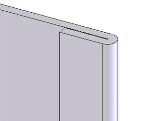
hemming is a process of folding of edges for a sheet to avoid sharp corners.it is generally used for wrap the outer most panels of the car.
CHEMICAL JOINIG PROCESS
chemical process is atype if joining process, here the two metals are dipped in a liquid having a chemical solution and joined through chemical reaction.
adhesive bonding
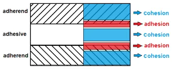
Adhesive Bonding is the process of joining two surfaces together, usually with the creation of a smooth bond. This may involve the use of glue, epoxy, or one of a wide range of plastic agents which bond either through the evaporation of a solvent or through curing via heat, time, or pressure.the procedure enables bonding temperatures from 1000 °C down to room temperature. The most important process parameters for achieving a high bonding strength are
- adhesive material
- coating thickness
- bonding temperature
- processing time
- chamber pressure
- tool pressure
Adhesive bonding has the advantage of relatively low bonding temperature as well as the absence of electric voltage and current. Based on the fact that the wafers are not in direct contact, this procedure enables the use of different substrates, e.g. silicon, glass, metals and other semiconductor materials. A drawback is that small structures become wider during patterning which hampers the production of an accurate intermediate layer with tight dimension control. Further, the possibility of corrosion due to out-gassed products, thermal instability and penetration of moisture limits the reliability of the bonding process. Another disadvantage is the missing possibility of hermetically sealed encapsulation due to higher permeability of gas and water molecules while using organic adhesives.
3.What is Resistance Welding & its application in the automotive sector?
Resistance welding, sometimes called electric resistance welding (ERW),is a process by which metals can be joined together by applying pressure and conducting a strong electric current through the metal combination to heat up the welding joint and melt the metals, forging them together.It has various forms and applications, and no other materials are needed, which makes it a highly cost effective process.Resistance welding is generally used to join two plain metal work pieces together. An electric current is delivered to the metal sheets (or any work pieces being joined) through weld electrodes which apply force to the sheets. This force is then converted to heat. The heat is generated so that it melts the metal at the point where they join – the point of ‘resistance’ between the faying surfaces. The electrode then extracts heat from the molten weld area which forms a weld nugget at the point where it solidifies. A force is applied before, during and after a current is applied, which confines the contact area.
types of resistance welding
There are many resistance welding processes with different uses, such as spot welding, seam welding, and butt welding. Each one has a different specific welding application that makes it optimal for a particular situation.
Resistance spot welding has been used extensively in the automotive industry for the joining of steel and in the aerospace industry for airframe components made from aluminium alloys. It is one of the oldest and simplest forms of resistance welding, in which a weld nugget is produced by passing an electric current between the two metal components whilst they are held together between electrodes, typically made from copper-based alloys due to its superior conductive properties.
Resistance seam welding is a variation of the standard spot welding form, however instead of spot one nugget, a series of overlapping nuggets is produced. This is usually done by replacing the conventional spot welding electrodes with wheels, which turn as the parts are fed between them. The process thus produces a continuous welded seam rather than a single spot. Seam welding is often used in the production of thin sheet, leak-tight containers such as fuel tanks, and is generally unsuitable for welding aluminium.
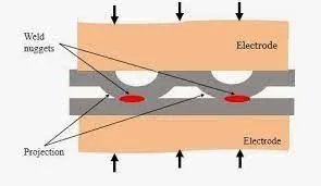
Resistance projection welding is a form of resistance welding where the electricity, force, and weld time are concentrated on raised ‘projections’ across the surface. Projection welding is generally used for welds using thicker materials than the thinner metal pieces that spot welding is usually required for, and often not metals. It is used primarily in the electrical, automotive and construction industries.
Resistance butt welding is a process in which the two components of similar cross section can be joined together in one operation that takes place simultaneously across the entirety of the affected object, rather than just in small spots. The welding application of butt welding is often in wires and rods with small diameter measurements, generally up to about 16mm diameter.
Flash butt welding is similar, but in this case the energy transfer is primarily provided by the resistance heat arising from the parts themselves. This is a faster type of resistance welding where the welder joins the parts by applying some pressure, then by passing a heavy current through the joint which burns away surface irregularities. After the weld has generated enough heat, the parts are connected by applying heat and pressure simultaneously. This produces a forge butt weld with no melted metal remaining in the joint.
Advantages
- Similar and dissimilar metals are capable of being welded
- Highly automated
- Efficient with high production rate and high welding rate
- Cost-effective
- Environment-friendly, produces little waste or pollution
- No need for filler metal or extraneous materials such as rods, fluxes, inert gasses, oxygen, or acetylene are required
Disadvantages
- Complex and often high-cost machinery – a resistance welding machine generally requires a high level of technically trained personnel to use
- The thickness of the work piece is often limited
- It is less efficient for high conductive materials
- High electric power required
spot welding
Spot welding (also known as resistance spot welding) is a resistance welding process. This welding process is used primarily for welding two or more metal sheets together by applying pressure and heat from an electric current to the weld area.
It works by contacting copper alloy electrodes to the sheet surfaces, whereby pressure and electric current are applied and heat is generated by the passage of current through resistive materials such as low carbon steels.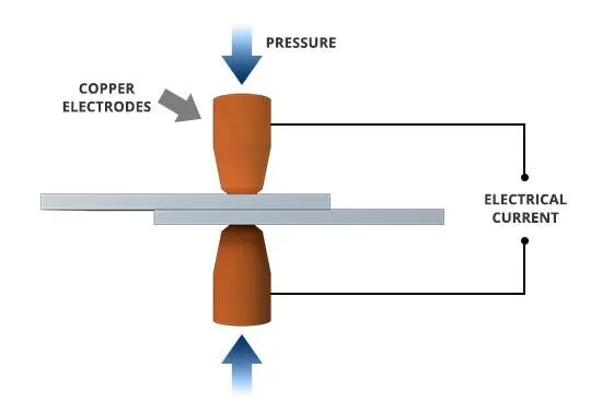
Applications
- automotive
- aero space
- rail
- ship building
- constructions
- electronics
- metal furniture
seam welding
Resistance seam welding is a variant of the basic resistance spot welding process. In spot welding a weld nugget is produced by passing an electric current through the sheet materials to be welded while they are held together under a mechanical force between shaped copper electrodes in a lap configuration. Fusion is produced where the sheet surfaces are in contact because this is the point of highest electrical resistance and hence the point where the temperature is highest.
In seam welding a series of overlapping nuggets is produced, usually by replacing the conventional spot welding electrodes by wheels that turn as the parts to be welded are fed between them. The process thus produces a continuous leaktight seam.
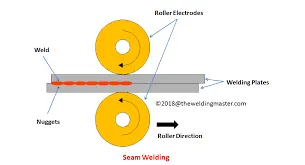
Butt welding
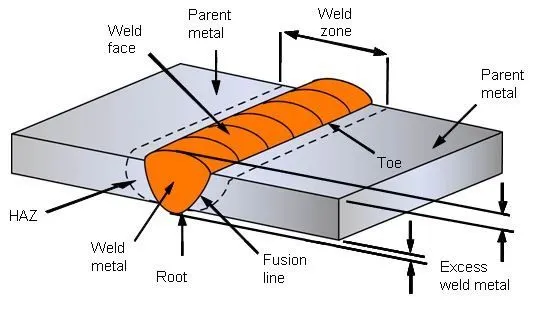
A butt weld is one of the simplest and versatile types of weld joint designs. The joint is formed simply by placing two pieces of metal end-to-end and then welding along the join. Importantly, in a butt joint, the surfaces of the workpieces being joined are on the same plane and weld metal remains within the planes of the surfaces. Thus, workpieces are nearly parallel and do not overlap, unlike lap joints, for example
classification
As mentioned earlier, various types of butt welding joints are named for their particular shape. The different types of joints include
single V,
double V,
single and double bevel,
single and double U, s
ingle and
double J joints,
square butt
Projection welding
he resistance welding process is commonly utilized in budget projects because it requires no additional materials outside of the metal that's being joined.
Fortunately, the cost-effective nature of the process doesn't translate to a less reliable weld. While differing welding methods vary in cost, the appropriate method is largely chosen by what is best suitable for the application.
Each type of welding has merit for particular types of jobs, including resistance welding.
Norstan offers our clients two varieties of resistance welding: spot and projection welding.
Projection welding is actually a modification of spot welding, the pioneer resistance welding process. Projection welding is generally used for projects with thicker materials (around 0.035” and thicker).
While it can be also used to join thinner metal pieces together, that tends to be a job left for spot welding.
4.What is fusion welding & types of fusion welding with its application in the automotive sector?
Fusion welding is a method that makes use of heat to combine or fuse two or more materials into a melting point by heating them. The method may involve the use of filler material, or it may not.
Outside pressure application is not needed for fusion welding processes, with the exception of resistance welding, where significant contact pressure is necessary for the sound joining during welding.
classification
- arc welding
- gas welding
- thermit welding
Arc Welding:
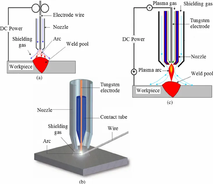
Arc welding refers to the group of welding processes in which the metals are heated to melting points by an electrical arc.
In some arc welding processes pressure is also applied to the workpiece for better weld strength and quality.
Most of the arc welding process makes use of filler material.
Arc Welding is further classified into the following types:
i) Shielded Metal Arc Welding (SMAW)
ii) Gas Metal Arc Welding (GMAW)
iii) Gas Tungsten Arc Welding (GTAW)
iv) Submerged Arc Welding (SAW)
v) Flux Cored Arc Welding (FCAW)
vi) Plasma Arc Welding (PAW)
vii) Carbon Arc Welding.
Gas Welding:
Gas welding is a welding process in which a strong high-temperature flame is used to weld two metal parts. The high-temperature flame is generated with help of flammable gases.
The flame is used to generate heat and raise the temperature of the metal piece at the place where the joint is to be made.
Due to the heat from the gas flame, the metal at the joints starts to melt. The molten metal is joined to another metal workpiece.
A filler material is also added to the molten metal to act as a binder. The molten joint is allowed to cool and solidify.
Many different combinations of gases are used to obtain a heating flame. The most common is oxygen-acetylene flame.
3) Thermite Welding:
Thermite welding is a welding process in which a thermite compound is used to weld two metals together. Thermite is a type of chemical composition of a metal powder. Powder normally consists of a metal and a metal oxide. When this powder is ignited, it undergoes an extremely exothermic redox reaction. Here oxide from one metal transfers to the other metal. In this welding process, a huge amount of heat is generated for a brief period. The most common use of thermite welding is to join rail tracks in railways.
This process does not require any heavy machinery and is very fast.
This process is also used to repair rail tracks as the molten metal from
the reaction can be used to repair the tracks.
4) Oxy-Fuel Welding:
It is the type of welding process in which oxygen is used as fuel to produce a flame that heats and joins two metal surfaces. This process is also known as oxy-acetylene welding.
This welding process uses a combination of oxygen and a flammable gas mostly acetylene to create a hot flame to join objects. Oxygen and fuel are mixed in the right proportion within a handheld torch or blowpipe to produce a hot flame with a temperature of about 3200 degrees Celcius.
As steel melts at 1500 degree Celcius, this is the only welding process which can produce such high temperature by combining oxygen and acetylene to melt steel. So steel can be welded using this welding process only. While other non-ferrous metals with low melting points can be welded by using a mixture of oxygen and gases like hydrogen, propane, or coal gas in the oxyfuel welding process.
5) Induction Welding:
In this type of welding process, electromagnetic induction is used to heat the metal surfaces which are to be joined. An induction coil is present in the welding apparatus which is energized with a radio-frequency electric current. This welding process is mainly used to weld materials that are either electrically conductive or are ferromagnetic materials.
Electrical insulators and non-magnetic materials can also be welded using this process by implanting them with ferromagnetic or metallic compounds called susceptors.
6) Laser Beam Welding:
Laser Beam Welding is a fusion welding process in which two metal pieces are joined using a laser.
Laser Beam Welding is done by focusing the laser beam to the cavity between the two metal parts. The laser beam strikes the metal parts and produces heat which melts the material of the two metals or the filler material.
After cooling of the molten metal, a weld is formed which is very strong.
Fusion VS Pressure Welding 200 words
Advantages Of Fusion Welding:
1) Fusion Welding can be used to join dissimilar materials easily.
2) External filler material can be added easily.
3) No external pressure is needed.
4) Using this process, more than two components can be welded at a step.
Disadvantages Of Fusion Welding:
1) Due to intense heating and subsequent melting, many mechanical and metallurgical properties are affected.
2) Because of excessive heat input, high distortion takes place.
3) Noticeable heat affected zone exists around the weld bead due to excessive heat.
4) Welding two dissimilar metals is difficult specially if the metals have different melting points and coefficient of thermal expansion
5.What is the 3-2-1 principle?
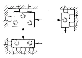
A fundamental concern in metalworking is locating the part to be machined, punched, bent, or stamped relative to the work platform (fixture). For example, a CNC machine tool starts its process at a specific point relative to the fixture and proceeds from there. Hence, the accuracy with which a part is machined is quite dependent on the accuracy with which it is positioned in the fixture.
Accurate locating of not just one part, but each and every part that is loaded into the fixture is crucial. Any variation in part location on the fixture adds to the dimensional tolerance that must be assigned to the finished parts.
Additionally, the method of supporting and securing the part in the fixture affects not only dimensional tolerances, but surface finishes as well. This is true because improper supporting or clamping can temporarily or permanently deform the part. Hence, techniques for supporting and clamping must be considered together with the method of locating in order to assure repeatability from part-to-part.
Locating of a part to be machined is a three-step process:
1. Supporting
2. Locating (positioning)
3. Holding (clamping)
The Locating Process: Degrees of Freedom
In order to completely specify the position in space of a three-dimensional
object (such as the cube that’s shown), we refer to six coordinates:
- Translational position along the X-axis
- Translational position along the Y-axis
- Translational position along the Z-axis
- Rotational position about the X-axis
- Rotational position about the Y-axis
- Rotational position about the Z-axis
These six coordinates are known as the six degrees of freedom of a three-dimensional object. As the double-headed arrows indicate, the translational and rotational positions can vary in either direction with respect to each of the three axes.
To completely prevent movement, all six degrees of freedom must be restricted.
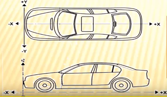
6.Define Body coordinate system?
- The body coordinate system is widely used in the automotive industries for drawing body products. and process design.A coordinate system is a reference system consistingof a set of points. lines.and surfaces used todefine the position of points inspace in either two or three dimensions.
- To represent the position of BIW car welding fixture and its unit assemblies with its individual parts (e.g. Mylar(the parts which are in contact with panel)) in 20 drawings. their respective positions are shown with reference to (X=O. Y=O. Z=O)positions. In shorl itshows in 20 XY.YZ.or XZ coordinate position of BIW welding fixture parts or assemblies with reference to origin X=O. Y=O. Z=OLet us consider a situation if an individual fixture designer starts designing a part or panel on their default axes system then it will be diff icult to assembly or position the part with respect to each other. So in order to avoid this all the designer starts designing with respect to car axes system (which isgenerally at the center of the front axle
7.Elaborate Body plane system & its essentials
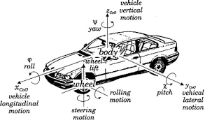
Body planes are reference planes in an automotive car.These planes are used to define the GD&T of all car parts inan automotive domain.Body planes are three mutually perpendicular imaginary planes. These aregenerally considered to be present at the driver position orsometimes at the engine location or at the f-ront end of the carThe measurements from the body planes to the body partsarecalled body tine dimensions.
The need of the body planes areas below
- It defines the exact position of each part of the car with respect to afixed origin.
- It ensures flawlessdesign for assembly.
- It assists in the location of different parts in the vehicle
- It creates a standard system
- It is very helpful in Quality checks.