Week 2:- BiW Fixture Basics Challenge
- What is the process of project execution activity?
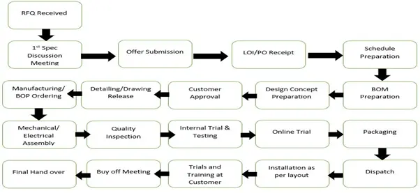
As shown in the figure there are various steps involved in project activities, They will be explained in detail below.
- RFQ: RFQ - Request For Quotation
- First spec discussion meeting
- Offer submission
- LOI/PO reciept
- Schedule preparation
- BOM prepation
- Design concept preparation
- Customer approval
- Detailing/ drawing release
- Manufacturing/ electrical assembly
- Quality inspection
- Internal trial &testing
- Online trail
- Packaging
- Dispatch
- Installation as per layout
- Trails & Training at customer
- Buy off meeting
- Final handover
1.RFQ:
Request for quotation
In this where the customer gives the requirments in detail for the given projects in the form of data or documents.
Also, the customer specifies its technical offer, commercial offer etc., how the project will be excecuted and the timeline of the project also will be mentioned.
- Discussion meeting;
After rfq received, technical offer , commercial offer, a timeline of the project etc., will be discussed and prepared from outside.
Based on the technical offer the commercial offer will be finalized.
- Offer submission;
After the finalization in the meeting, the offers will be submitted to the customer end.
Customer will arrange to get an offer from other suppliers too.
Based on the technical, cost ,quality, standard and name in the industries, the customer will be finalizing the offer.
- LOI/PO Receipt;
Here customer will be releasing the LOI/PO purchase order
Once PO is released we have to start the work.
After getting PO from the customer we have to prepare the schedule.
- Schedule preparation;
Once the PO released from the customer we will be working on preparation of schedule which should be matched our planned commitment in the technical offer customer required time.
- BOM preparation
Bill of materials like cylinders , motors etc., which is required for the project are prepared.
- Design concept preparation
Before the design concept we have to study the data of the customer requirement thoroughly which is carried out in design data study activities.
During the design data study, we will proceed with rough sketches to get a flow while designing concepts.
In this concept preparation, we should conceptualize the basic data like spot plan, cycle time etc.
- Customer approval;
It is also known as the design approval process.
After design concepts the customer will review the design concepts.
- Detailing &Drawing release;
The detailing of the fixture parts which is to be manufactured has been done with given appropriate dimensions and GD&T symbols.
All the dimensions which are the necessity for manufacturing should be included with gd&t in the drawings before releasing the drawing to the manufacturing team.
- Manufacturing/BOP ordering;
The mechanical and electrical parts like sensors, cylinders. Etc., which needs for a fixture or ordered as per the design specifications.
- Mechanical/ Electrical assembling;
After the materials ordered received to our end. The quality will check the working conditions and technical specs. Which meets our requirements.
After they will be assembled as per the design.
- Quality Inspection;
In all dimensions, positional accuracy, coordinates are checked using CMM.
- Internal Trial;
After QC check internal trials are made to check the operation of the fixture.
It is a first trial taken in house, the pins are getting into holes, clamping operation, assembly /panel suited correctly etc.
- Online Trail;
The trail will be done in automatically made through the control panel.
The process sequence of operations is checked as by the designed way.
- Packaging;
To avoid damage occur in fixtures while transporting which may also lead to affect the aesthetic look & proper function of fixture packaging has been done.
After approval of QC ,packaging is been done as per standards, so packaging should be one as per standards.
- Dispatch;
After the fixture has been packed for delivery as per standards.
Its been dispatched to the customer.
- Installation as per layout;
The design of the layout are been prepared at a very initial level which gives the information of placements of robots and fixtures.
According to the design the installation and commission team will install the fixtures.
- Trails & Training at customer;
Production trails will taken at the customer end.
The checkpoints which has to be done after placing the panels into the fixture will be made clear to them.
- Buyoff meeting;
In this meeting customer will give reviews about the fixtures, sometimes customer may need to do some additional work also. It will be discussed and finalize in the meeting.
- Final handover;
The fixture and the documents support the fixture will be handed over.
Documents like clamp validation documents, ergo sheets, BOMs , charts will delivered to the customers.
Every automobile industries will follow some standards to maintain the documents as per ISO, IATF.
- 2. What are the types of joining processes?
Joining of materials
• Joining includes welding, brazing, soldering, adhesive bonding of materials.
• They produce permanent joint between the parts to be assembled.
• They cannot be separated easily by application of forces.
• They are mainly used to assemble many parts to make a system.
• Welding is a metal joining process in which two or more parts are joined or coalesced at their contacting surfaces by suitable application of heat or/and pressure.
• Some times, welding is done just by applying heat alone, with no pressure applied
• In some cases, both heat and pressure are applied; and in other cases only pressure is applied, without any external heat.
• In some welding processes a filler material is added to facilitate coalescence.
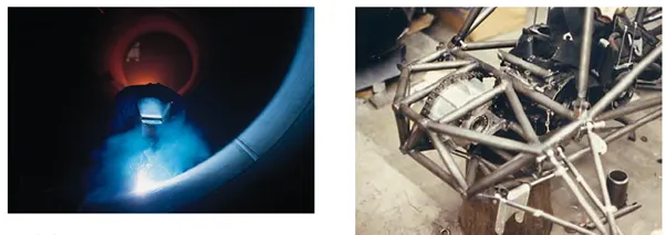
Advantages of welding:
• Welding provides a permanent joint.
• Welded joint can be stronger than the parent materials if a proper filler metal is
used that has strength properties better than that of parent base material and if
defect less welding is done.
• It is the economical way to join components in terms of material usage and fabrication costs. Other methods of assembly require, for example, drilling of holes and usage of rivets or bolts which will produce a heavier structure.
Disadvantages of welding:
• Labour costs are more since manual welding is done mostly.
• Dangerous to use because of presence of high heat and pressure.
• Disassembly is not possible as welding produces strong joints.
• Some of the welding defects cannot be identified which will reduce the strength.
Types of welding: Welding processes can be broadly
classified into (i) fusion welding, and (ii) solid state welding
Fusion welding:
In fusion-welding processes, heat is applied to melt the base metals. In many fusion welding processes, a filler metal is added to the molten pool during welding to facilitate the process and provide strength to the welded joint.
When no filler metal is used, that fusion welding operation is
referred to as autogenous weld.
Types: Arc welding, Resistance welding, Oxyfuel gas welding, electron beam welding, laser welding
Arc welding: In this operation, electric arc is used to produce heat energy and the base metal is heated. Sometimes, both pressure and heat are applied.
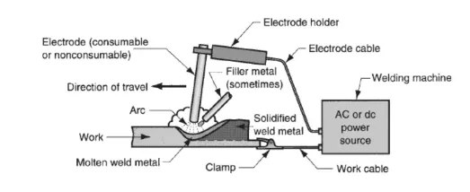
Arc welding steps
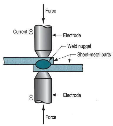
Resistance welding: In this operation, electric resistance is generated to the flow of current that generates heat energy between two contacting surfaces that are held in pressure.
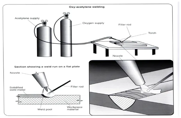
Gas welding: Oxyfuel gas welding is a welding operation in which heat is generated by a hot flame generated mixture gas of oxygen and acetylene. This heat is used to melt base material and filler material, if used.
Solid State Welding:
• In this method, joining is done by coalescence resulting from application of pressure only or a combination of heat and pressure.
• Even if heat is used, the temperature in the process is less than the melting point of the metals being welded (unlike in fusion welding).
• No filler metal is utilized.
Diffusion welding: Two part surfaces are held together under pressure
at elevated temperature and the parts join by solid state diffusion.
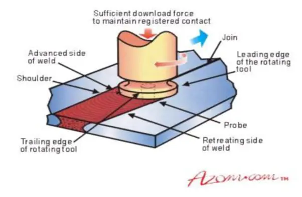
Friction welding/Stir welding: Joining occurs by the heat of friction and plastic deformation between two surfaces.
Ultrasonic welding: Moderate pressure is applied between the two parts and an oscillating motion at ultrasonic frequencies is used in a direction parallel to the contacting surfaces.
Weld joint configurations
Butt joint Corner joint Lap joint Tee joint Edge joint
Weld types
Fillet welds
Inside single fillet
corner joint Outside single fillet
corner joint Double fillet lap
joint Double fillet
Tee joint
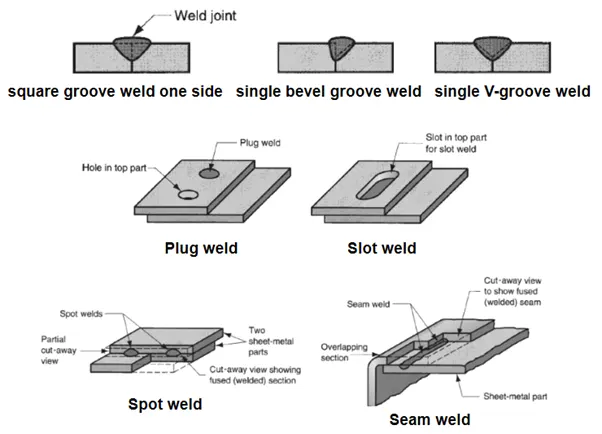
square groove weld one side single bevel groove weld single V-groove weld
Plug weld Slot weld
Spot weld Seam weld

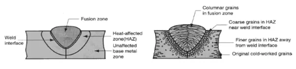
Morphology of fusion weld
A typical fusion weld has got few zones like (i) fusion zone, (ii) weld
interface, (iii) heat affected zone, (iv) unaffected base material.
Fusion zone: It consists of a mixture of filler metal and base metal that have completely melted. A high degree of homogeneity is present among the component metals that have been melted during welding.
In fusion zone, the solidification occurs by epitaxial grain growth, in which the atoms in the molten metal solidify at the pre existing lattice sites in the unaffected base material. Moreover the grain structure in the fusion zone has got preferred orientation and they are oriented roughly perpendicular to the weld interface. This results in coarse columnar grains in fusion zone.The grain structure depends on various factors namely welding technique, metals being welded like similar metals and dissimilar metals welded, usage of a filler metal, and the traverse speed at
which welding is done. Weld interface: It is a narrow boundary that separates the fusion zone from heat affected zone. This zone consists of a thin band of base
metal that was partially melted during the welding process but immediately solidified without mixing with the metal in the fusion zone. Its chemical composition is generally same as that of the base metal. Heat affected zone: This zone is between weld interface and base material. This experience temperatures below melting point, but sufficient enough to change the microstructure and hence the
mechanical properties.
The mechanical properties are such that most of the failures occur in
this region. Base material: Unaffected because of heat generation and preserve
the initial microstructure.
Heat energy in fusion welding The amount of heat required to melt a given volume of material depends on,
(i) heat energy required to change the temperature of solid metal to its melting
point that depends on volumetric specific heat, (ii) melting point of material,
(iii) heat required to change the solid to liquid phase that depends on heat of
fusion of the material. The quantity of heat required to melt a given volume of metal from room
temperature (Um in J/mm3 ) is given by,
Um = K Tm2
Tm - melting point of the metal in K, K – constant, 3.33×10⁻⁶
The heat energy generated by the heat source is not fully used for melting
the material.
Two important factors are defined for the losses. They are, heat transfer factor,
F1, and melting factor, F2.
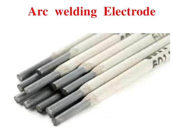
Electrodes
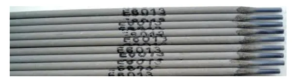
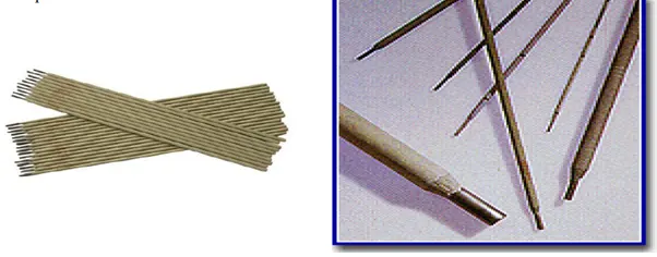
Two types of electrodes are used: consumable and non-consumable
• Consumable electrodes:
Present in rod or wire form with 200 to 450 mm length and less than 10 mm
diameter. This is the source of filler rod in arc welding.
The electrode is consumed by the arc during the welding process and
added to the weld joint as filler metal.
The consumable electrodes will be changed periodically as it is consumed
for each welding trials. This becomes a disadvantage for welder and
reduces the production rate.
• Non-Consumable electrodes:
The electrodes are not consumed during arc welding. Though this is the
case, some depletion occurs because of vaporization.
Filler metal must be supplied by means of a separate wire that is fed into
the weld pool.
Arc shielding:
Shielding gas:
This covers the arc, electrode tip and weld pool from external atmosphere.
The metals being joined are chemically reactive to oxygen, nitrogen, and
hydrogen in the atmosphere.
So the shielding is done with a blanket of gas or flux, or both, which inhibit
exposure of the weld metal to air.
Common shielding gas: Argon, Helium
Flux:
Used mainly to protect the weld region from formation of oxides and other
unwanted contaminants, or to dissolve them and facilitate removal.
During welding, the flux melts and covers the weld region giving protection
and it should be removed by brushing as it is hardened.
Additional function, other than giving protection: stabilize the arc, and
reduce spattering
Power source in arc welding:
Both AC and DC can be used; DC is advantageous as better arc control is
possible.
Polarity:
Straight polarity in which workpiece is positive and electrode is negative is
suitable for shallow penetration (like in sheets) and joints with wide gaps.
Reverse polarity in which workpiece is negative and electrode is positive is
suitable for deeper welds.
The power balance in arc welding is given by, RHw = F1F2 I E = Um Aw v.
Here E - voltage, I – current.
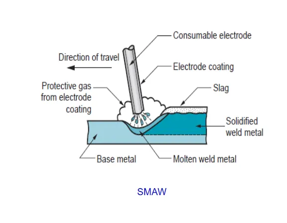
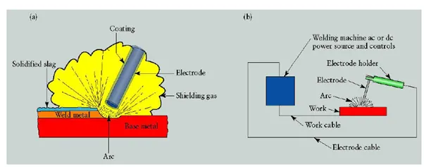
Shielded metal arc welding (SMAW): - In this process, a consumable electrode consisting of a filler metal rod which is coated with chemicals that provide flux and shielding, is used. - Generally the filler metal has chemical composition very close to base metal. - Filler rod coating: Coating consists of powdered cellulose (cotton and wood powders) mixed with oxides, carbonates, combined using a silicate binder. - This coating provides protective layer to the weld pool and stabilizes the
arc.
- current: < 300 A; Voltage: 15 – 45 V. - Applications: ship building, construction, machine structures etc. - Materials: grades of steel, stainless steel etc. are welded. Al, Cu, Ti alloys
are not welding using SMAW.
- Disadvantages: repeated change of electrodes, current maintained in
typical range
SMAW
Gas metal arc welding (GMAW):
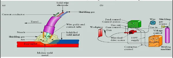
- In this process, electrode is a consumable wire
(0.8 to 6.5 mm diameter). - shielding gas is provided separately over arc
by a pipe - Shielding gas: Helium, Argon, mixture of
gases; used mainly for Al alloys.
- active gases like CO2 is used for welding steel
grade material. - As compared to SMAW, GMAW can be used
for multiple weld passes as there is no
deposition of slag and hence no brushing
involved. (advantage) - advantage: automation of welding possible as
continuous weld wires are used, and not sticks
as in SMAW. - Also called MIG (metal inert gas) welding, CO2
welding (when CO2 is used).
GMAW
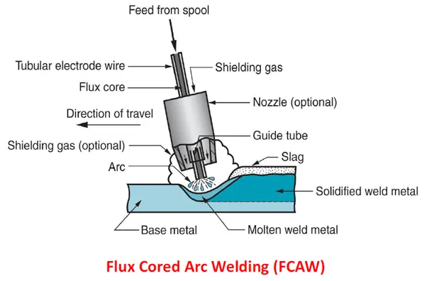
Flux cored arc welding (FCAW):
- arc welding process in which the electrode is a continuous consumable tubing that contains flux. - Self-shielded FCAW: the arc shielding was provided by the flux core. The core also includes ingredients that generate shielding gases for protecting the arc. - Gas shielded FCAW:
Shielding is done from externally supplied gases. Since it uses both flux and
shielding gas (provided separately), it is considered as a hybrid of SMAW
and GMAW.
FCAW
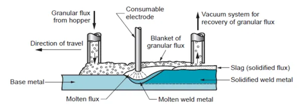
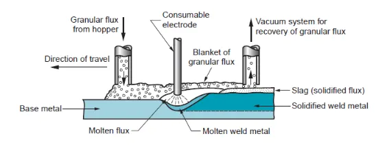
Submerged arc welding (SAW): - In this process, a continuous bare electrode wire is used. The shielding is provided by external granular flux through hopper. - Granular flux is provided just before the weld arc. - granular flux completely provides protection from sparks, spatter, and radiation and hence safety glasses, gloves can be avoided. - some part of flux gets melted and forms a glassy layer. - This layer and unfused flux results in slow cooling rate and good weld quality.
- The unused flux can be reused.
- application: longitudinal and circumferential welds for large diameter pipes, tanks, and pressure vessels; welded components for heavy machinery. Steel plates of 25 mm thick are welded.
Brazing
It is a joining process in which a filler metal is melted and distributed by capillary action between the faying (contact) surfaces of the metal parts being joined.
• Base material does not melt in brazing, only the filler melts.
• In brazing, the filler metal has a melting temperature (liquidus) above 450°C, but below the melting point (solidus) of base metals to be joined.
Advantages of brazing
• Brazing can be used to join a large variety of dissimilar metals.
• Pieces of different thickness can be easily joined by brazing
• Thin-walled tubes & light gauge sheet metal assemblies not joinable by welding can be joined by brazing.
• Complex & multi-component assemblies can be economically fabricated with the help of brazing.
• Inaccessible joint areas which could not be welded by gas metal or gas tungsten arc spot or seam welding can be formed by brazing.
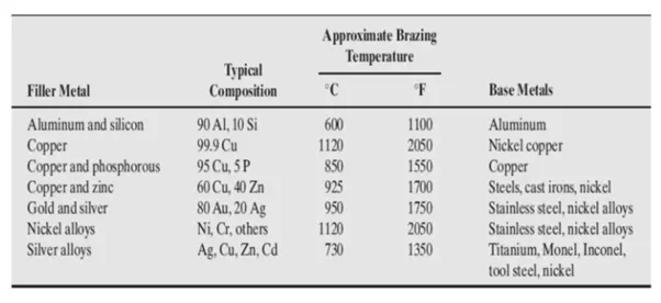
Filler materials used for brazing
Brazing fluxes
Characteristics of a good flux include,
(1) low melting temperature,
(2) low viscosity so that it can be displaced by the filler metal,
(3) facilitates wetting, and
(4) protects the joint until solidification of the filler metal.
On the basis of method of heating, various brazing process are:
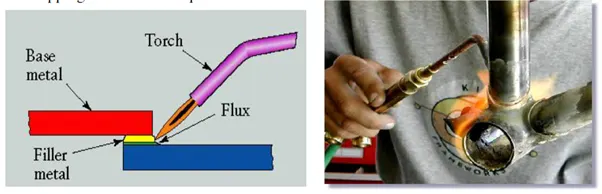
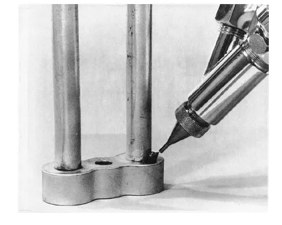
Torch brazing
• Flux is applied to the part surfaces and a torch is used to direct a flame against the work in the vicinity of the joint.
• After the workpart joint areas have been heated to a suitable temperature, fillerwire is added to the joint, usually in wire or rod form.
• Fuels used in torch brazing include acetylene, propane, and other gases, with air or oxygen.
• Torch brazing is often performed manually, and skilled workers must be employed. Other types: Furnace brazing, Induction brazing, Resistance
brazing, Dip brazing, Infrared brazing
SOLDERING
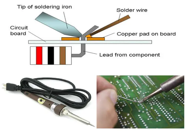
Soldering is similar to brazing and can be defined as a joining process in which a filler metal with melting point (liquidus) not exceeding 450°C is melted and distributed by capillary action between the faying surfaces of the metal parts being joined. As in brazing, no melting of the base metals occurs, but the filler metal wets and combines with the base metal to form a metallurgical bond.
Filler metal, called Solder, is added to the joint, which distributes itself between the closely fitting parts.
SOLDER: Alloys of Tin and Lead. Tin is chemically active at soldering temperatures and promotes the wetting action required for successful joining.
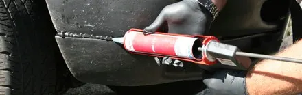
Adhesive Bonding is the process of joining two surfaces together, usually with the creation of a smooth bond. This may involve the use of glue, epoxy, or one of a wide range of plastic agents which bond either through the evaporation of a solvent or through curing via heat, time, or pressure.Glues have tended to create relatively weak joins but with the use of new self-curing adhesives these bonds are now close to the strength of the materials themselves. As a result, gluing is now the preferred method of joining for many applications, particularly when the bond is not exposed to prolonged heat or weathering.Many modern glues are carbon-based petrochemical derivatives, which can be used for a variety of joining applications including bonding metal and dissimilar materials. This type of adhesive uses either direct contact or a third surface, such as an adhesive tape, to create the bond.
Among the composite applications that are commonly bonded using adhesives are fibreglass, and fibre-epoxies like boron-epoxy and carbon-epoxy. Due to their shear strength and toughness, modern adhesives can also serve to join structural materials, of which plywood is a common and well-known example.
What are the Advantages of Adhesive Bonding?
One of the main advantages of adhesive bonding is that it allows for the even distribution of stress loads, thereby reducing the stress on the joint. Since they are applied inside the join, adhesives are also invisible within the assembly.The properties of glues mean that they can form both an adhesive and sealant at the same time, while also resisting vibration and flexing stresses. The ability to act as a seal allows adhesives to help protect a join from corrosion.While adhesive bonding can be applied to metal-to-metal, plastic, glass, rubber, ceramic and many other material combinations, the process can be used to join irregularly shaped surfaces while offering virtually no change in the dimensions or geometry of the parts.Adhesives also add very little by way of weight to the materials being joined and can be used to quickly bond dissimilar substrates and heat-sensitive materials.One of the greatest advantages of adhesive bonding is the versatility it affords, allowing for joining of a wide range of items as well as being easy to automate.
What are the Disadvantages of Adhesive Bonding?
There are, however, a number of limitations to using adhesives. Firstly, they are prone to failure when exposed to high heat or weathering. Adhesives can also take time to fully fix and acquire full strength. They also often require surface preparation treatments including cleaning the surface of the materials to be joined. Other surface treatments associated with adhesives include abrasion to create a stronger bond.Adhesives can also cause problems related to disassembly when compared to other, less permanent joining techniques.
Where is Adhesive Bonding Used?
Adhesive bonding is used across many industries including automotive, aerospace, medical and even textiles. Due to the versatility of this process for a range of material types the only real limitations arise with use, such as for outdoor applications that need to withstand weathering.
Riveting and Bolting
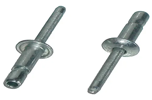
Riveting and bolting processes mechanically join magnesium with other metals by using mechanical fasteners including rivets, bolted joints, locking bolts, self-cinching nuts, screws, and various insert types. Use riveting and bolting for applications that require high strength and high production rates. For successful metal merging, prepare joint surfaces using materials that specifically prevent galvanic corrosion. Fasteners, rivets, screws, and bolts do not contain magnesium, so the metal or alloy chosen must be appropriate for magnesium–to–aluminum or magnesium–to–steel joining. When using steel, brass, or nickel fasteners, apply electroplated zinc or tin and chemically treatthe resulting alloy to optimize paint adhesion and delay galvanic corrosion. Organic coatings and temperature–resistant fluorinated hydrocarbon resin coatings provide maximum protection against galvanic corrosion, and they are most effective when applied to both the dissimilar metal and magnesium.
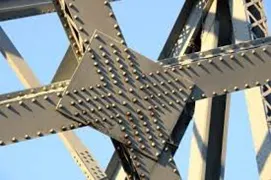
Plate inserts in cadmium, tin, or zinc. The self-piercing rivet (SPR) technique can be used with a galvanic insulator, although it must be preheated to prevent corrosion. When using bolting to join metals to magnesium, it’s best to place aluminum alloy washers under bolt heads and nuts. Commonly used compatible alloys include 5056, 5052, and 6061.
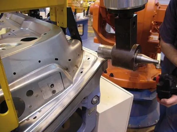
Hemming is a sheet metal forming process in which sheets are joined by bending it usually to 180°. Automotive body panels and automotive parts such as deck-lids, trunk-lids, doors, hoods and tailgates are formed by hemming process. This paper present a systematic review of sheet metal hemming process based on materials used in hemming process, analytical models, experimental and computational investigations made in the domain of sheet metal hemming process. Various grades of high strength sheets, aluminium alloys, recycle-friendly aluminium alloys, magnesium alloys, light weight alloys are used as workpiece materials in hemming process. Analytical models are also presented by few researchers for development in hemming process. New experimental set-up and novel experimental strategies of hemming process are devised and also adopted by researchers in past. Classical hemming, roller hemming, robot assisted roller hemming, laser assisted roller hemming and hemming with electromagnetic forming processes are the experimental different approaches utilized for performing sheet metal hemming operations. In FEM simulation of hemming process, three dimensional solid elements, shell elements and their combination are mostly employed by researchers in meshing of sheet metal blanks in hemming process. FEM simulation found to be an efficient tool for prediction of defects in hemming process and for optimization of process parameters as well. Besides, FEM simulation new computational approaches such as meta-model strategy are also applied for efficient design of hemming process.
- What is Resistance Welding & its application in the automotive sector?
Resistance welding, sometimes called electric resistance welding (ERW),is a process by which metals can be joined together by applying pressure and conducting a strong electric current through the metal combination to heat up the welding joint and melt the metals, forging them together.
It has various forms and applications, and no other materials are needed, which makes it a highly cost effective process.
How Does Resistance Welding Work?
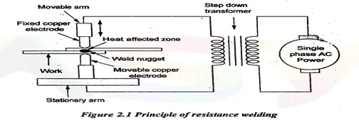
Resistance welding is generally used to join two plain metal work pieces together. An electric current is delivered to the metal sheets (or any work pieces being joined) through weld electrodes which apply force to the sheets. This force is then converted to heat. The heat is generated so that it melts the metal at the point where they join – the point of ‘resistance’ between the faying surfaces. The electrode then extracts heat from the molten weld area which forms a weld nugget at the point where it solidifies. A force is applied before, during and after a current is applied, which confines the contact area.
Types of Resistance Welding
There are many resistance welding processes with different uses, such as spot welding, seam welding, and butt welding. Each one has a different specific welding application that makes it optimal for a particular situation.
1. Resistance Spot Welding
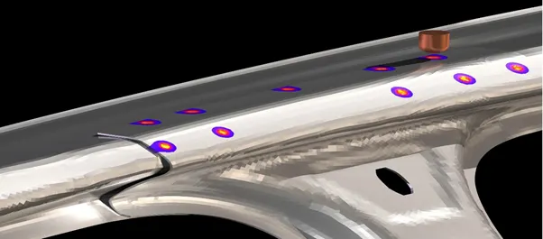
Resistance spot welding has been used extensively in the automotive industry for the joining of steel and in the aerospace industry for airframe components made from aluminium alloys. It is one of the oldest and simplest forms of resistance welding, in which a weld nugget is produced by passing an electric current between the two metal components whilst they are held together between electrodes, typically made from copper-based alloys due to its superior conductive properties.
2. Resistance Seam Welding
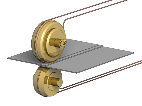
Resistance seam welding is a variation of the standard spot welding form, however instead of spot one nugget, a series of overlapping nuggets is produced. This is usually done by replacing the conventional spot welding electrodes with wheels, which turn as the parts are fed between them. The process thus produces a continuous welded seam rather than a single spot. Seam welding is often used in the production of thin sheet, leak-tight containers such as fuel tanks, and is generally unsuitable for welding aluminium.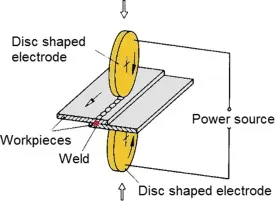
3. Resistance Projection Welding
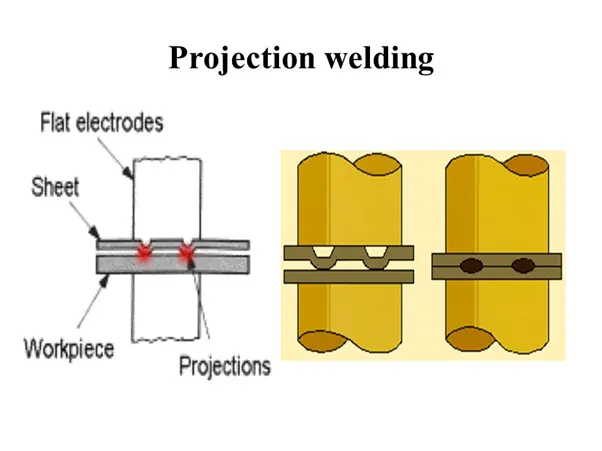
Resistance projection welding is a form of resistance welding where the electricity, force, and weld time are concentrated on raised ‘projections’ across the surface. Projection welding is generally used for welds using thicker materials than the thinner metal pieces that spot welding is usually required for, and often not metals. It is used primarily in the electrical, automotive and construction industries.
4. Resistance Butt Welding
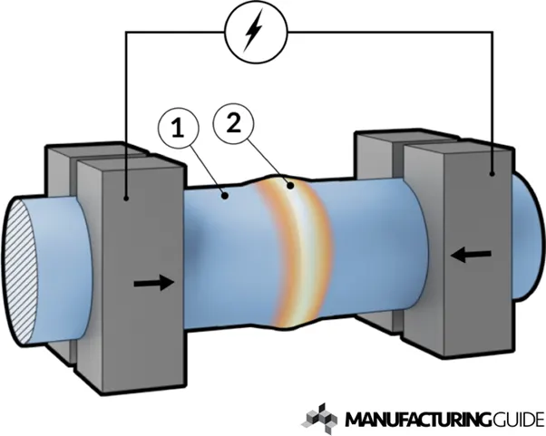
Resistance butt welding is a process in which the two components of similar cross section can be joined together in one operation that takes place simultaneously across the entirety of the affected object, rather than just in small spots. The welding application of butt welding is often in wires and rods with small diameter measurements, generally up to about 16mm diameter.
5. Flash Butt Welding
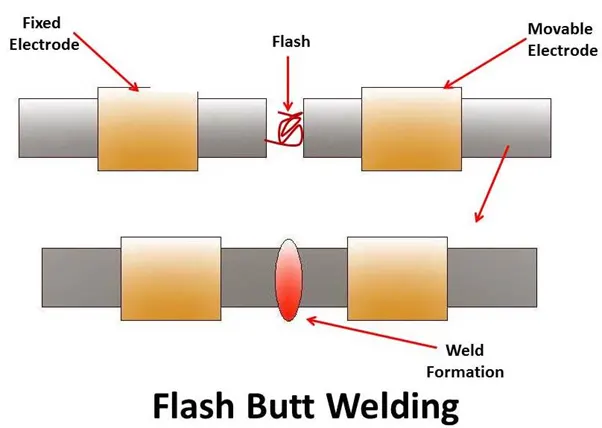
Flash butt welding is similar, but in this case the energy transfer is primarily provided by the resistance heat arising from the parts themselves. This is a faster type of resistance welding where the welder joins the parts by applying some pressure, then by passing a heavy current through the joint which burns away surface irregularities. After the weld has generated enough heat, the parts are connected by applying heat and pressure simultaneously. This produces a forge butt weld with no melted metal remaining in the joint.
Advantages
- Similar and dissimilar metals are capable of being welded
- Highly automated
- Efficient with high production rate and high welding rate
- Cost-effective
- Environment-friendly, produces little waste or pollution
- No need for filler metal or extraneous materials such as rods, fluxes, inert gasses, oxygen, or acetylene are required
Disadvantages
- Complex and often high-cost machinery – a resistance welding machine generally requires a high level of technically trained personnel to use
- The thickness of the work piece is often limited
- It is less efficient for high conductive materials
- High electric power required.
- What is fusion welding & types of fusion welding with its application in the automotive sector?
Fusion welding is a process that uses heat to join or fuse two or more materials by heating them to melting point. The process may or may not require the use a filler material. External application of pressure is not required for fusion welding processes, except for resistance welding, where substantial contact pressure is required during welding for sound joining.
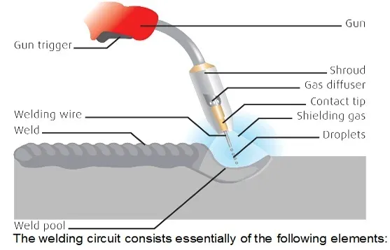
Fusion Welding Processes
Fusion welding processes can be grouped according to the source of the heat, for example, electric arc, gas, electrical resistance and high energy.
These processes include:
Arc Welding Processes - with the most common processes being:
Shielded Metal Arc Welding (SMAW), also known as manual metal arc welding (MMA or MMAW), flux shielded arc welding or stick welding. Suitable for welding ferrous and non-ferrous materials in all positions.
Metal Inert Gas Welding (MIG) and Metal Active Gas Welding (MAG), also known as Gas Metal Arc Welding (GMAW). MIG and MAG welding are the most common arc welding processes, in which an electric arc forms between a consumable wire electrode and the workpiece leading them to melt and join. Both use a shielding gas to protect the weld from airborne contaminants, or oxidation in the case of MIG welding.
Tungsten Inert Gas Welding (TIG), also known as Gas Tungsten Arc Welding (GTAW). This arc process uses a non-consumable tungsten electrode to create the arc between the electrode and the base plate. An inert shielding gas is used to protect from oxidation or other atmospheric contamination. This process can be used autogenously on thin parts, but will require the addition of a wire, rod, or consumable to be added for thicker parts.
Plasma arc welding(PAW). This process uses an electric arc created between an electrode and the torch nozzle. The electric arc ionises the gas (usually argon) in the chamber creating what is called a 'plasma.' It is then forced through a fine bore copper nozzle that constricts the arc and directs it to the workpiece, allowing the plasma arc to be separated from the shielding gas (which is usually made from a mixture of argon and hydrogen).
Submerged arc welding(SAW). This frequently-used arc welding process uses a continuously-fed consumable electrode and a blanket of fusible flux which becomes conductive when molten and provides a current path between the workpiece and the electrode. The flux also prevents spatter and sparks while suppressing ultraviolet radiation and fumes.
Flux Cored Arc Welding (FCAW). Developed as an alternative to SMAW, this process uses a continuously fed consumable electrode with a flux and a constant voltage or constant current power supply. Sometimes using a shielding gas this process can also just use the flux to provide protection from the atmosphere.
Gas Welding Processes - the most common process being:
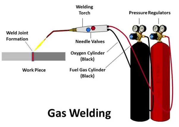
Oxy-Fuel Welding, also known as Oxyacetylene Welding but commonly called gas welding, this process uses a hand-held torch or blow pipe and a mixture of oxygen and acetylene which combusts to create a flame.
Resistance Welding Processes
Resistance Spot Welding. This fast welding process delivers heat between two electrodes according to the material properties and thickness of the workpieces. The welding current is concentrated to a small spot as the workpieces are simultaneously clamped together.
Resistance Seam Welding. This variant of spot welding produces a series of overlapping nuggets of a continuous joint by replacing conventional spot welding electrodes with wheels which rotate as the workpieces are fed between them.
High Energy Welding Processes - with the main ones being:
Electron Beam Welding (EBW). This fusion process is performed under vacuum conditions, using a beam of high velocity electrons to melt the workpieces as the electrons generate heat upon penetration into the material. Welds are often deep and narrow.
Laser Beam Welding (LBW). Often used in high volume applications, LBW uses a laser beam to provide a concentrated heat source with high levels of accuracy which can be used to join metal and polymers.
Advantages of using Fusion Welding?
- Edge preparation and joint design are not imperative as these will only affect achievable penetration
- Large spaces can be filled due to the ease of applying filler material
- The primary shape of components does not matter as there is no need to apply external pressure
- Fusion welding allows for the easy joining of more than two components
Disadvantages of using Fusion Welding?
- Difficult to join dissimilar metals when they have different melting points and thermal expansion coefficients
- Intense heating can severely affect the mechanical properties of parent materials
- Melting and solidification can generate distortion and residual stress
- The heat affected zone (HAZ) creates a weak area in the welded materials.
5.What is the 3-2-1 principle?
Principle of Location in Jig And Fixture:
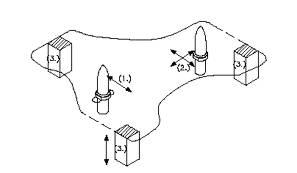
The principle of location is being discussed here with the help of a most popular example which is available in any of the book covering jigs and fixtures. It is important that one should understand the problem first.
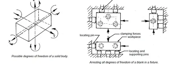
Any rectangular body many have three axis along x-axis, y-axis and z-axis. It can more along any of these axes or any of its movement can be released to these three axes. At the same time the body can also rotate about these axes too. So total degree of freedom of the body along which it can move is six. For processing the body it is required to restrain all the degree of freedom (DOF) by arranging suitable locating points and then clamping it in a fixed and required position. The basic principle used to locate the points is desirable below.
Locating – principles and methods
3-2-1 Principle of Location used in Jig & Fixtures:
It is also known as a six-pin or six-point location principle. In this, the three adjacent locating surfaces of the blank (workpiece) are resting against 3, 2, and 1 pin respectively, which prevent 9 degrees of freedom.
The rest three degrees of freedom are arrested by three external forces usually provided directly by clamping.
3 2 1 principle used in jig fixture design
We have two objectives when mounting a part in a fixture for machining:
1. Accurately position the part at the desired coordinates.
2. Restrict all six degrees of freedom so that the part cannot move.
A widely used method of accomplishing these two objectives uses the 3-2-1 principle, so-called because it entails three steps that employ three, then two, then one fixed points of known location. Since that adds up to six fixed points, it’s also known as the six point method.
In the three steps of the 3-2-1 method, three mutually perpendicular planes, called datum planes, are introduced, one at each step. These three planes define the workpiece position, and together with opposing clamping forces fully constrain the part. Let’s take a look at the details of the 3-2-1 method.
3-2-1 Principle Statement :
The 3-2-1 principle states that the six locators are sufficient to restrict the required degree of freedom of any workpiece. In this, motion is restricted using clamps and locators. A three-pin base can restrict five motions and six pins restrict nine motions.
Methodology of 3-2-1 Principle:
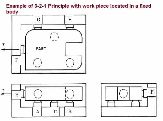
For this, refer the below figure;
[1] The workpiece is resting on three pins A, B, and C which are inserted in the base of the fixed body.
[2] The workpiece cannot rotate about the axes XX and YY and also cannot move downward.
[3] In this way, the five degrees of freedom 1,2,3,4 and 5 have been arrested.
[4] Two pins D and E are inserted in the fixed body, in a plane perpendicular to the plane containing pins A, B & C.
[5] Now the workpiece cannot rotate about the Z-axis and also it cannot move towards the left.
[6] Hence the addition of pins D and E restrict three more degrees of freedom, namely 6, 7, and 8.
[7] Another pin F in the second vertical face of the fixed body, arrests degree of freedom 9.
The above method of locating a workpiece in a fixture is called the 3-2-1 Principle.
Summary of 3-2-1 Principle:
A workpiece will be completely confined when blanked against:
- 3 points in one plane: The “3” in 3-2-1 refers to 3 locators (passive fixture elements) on the primary locating/datum surface.
- 2 points in another plane: The “2” in 3-2-1 refers to 2 locators on the secondary locating/datum surface.
- 1 point in a third plane: The “1” in 3-2-1 refers to 1 locator on the tertiary locating/datum surface
Some basic principles or rules need to be followed while planning for locating blanks in fixtures, such as;
- One or more surfaces (preferably machined) and/or drilled/bored hole(s) are to be taken for reference
- The reference surfaces should be a significant and important feature(s) based on which most of the dimensions are laid down
- Locating should be easy, quick and accurate In case of locating by pin, the pins and their mounting and contact points should be strong, rigid and hard
- A minimum of three-point must be used to locate a horizontal flat surface
- The locating pins should be as far apart as feasible
- Vee block and cones should be used for self-locating solid and hollow cylindrical jobs.
Types Of Locators used In Jig And Fixture For supporting :
The location arrangement depends on the type of operation, degrees of required accuracy.
- Flat locators: These are used for the location of the flat machined surfaces of a component.
- Cylindrical locators: These are used for the location of components with drilled holes.
- Conical locators: These locators are used to support the workpieces with cylindrical holes.
- Jack pin locators: These locators support rough workpieces.
- Drill bush locators: These locators hold and locate the cylindrical workpieces.
- Vee locators: These locators hold circular and semicircular workpieces.
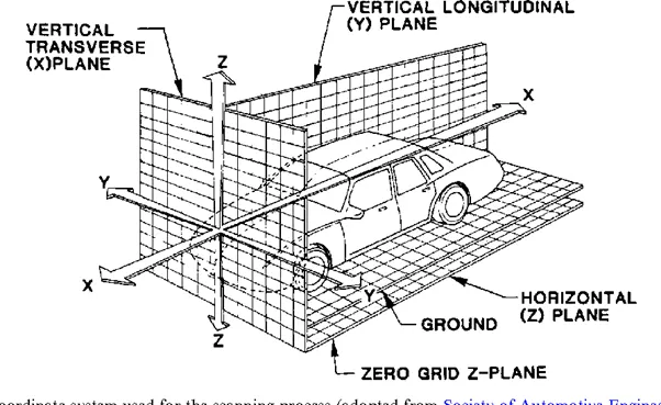
- Define Body coordinate system?
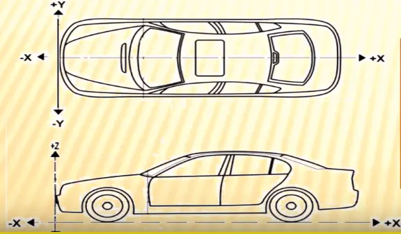
Body Coordinate System
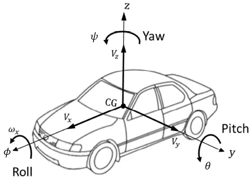
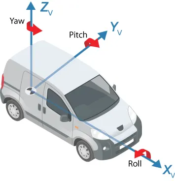
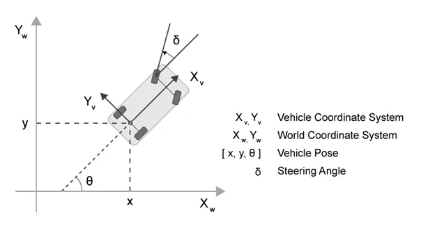
The vehicle coordinate system (XV, YV, ZV) used by Automated Driving Toolbox is anchored to the ego vehicle. The term ego vehicle refers to the vehicle that contains the sensors that perceive the environment around the vehicle.
- The XV axis points forward from the vehicle.
- The YV axis points to the left, as viewed when facing forward.
- The ZV axis points up from the ground to maintain the right-handed coordinate system.
The vehicle coordinate system follows the ISO 8855 convention for rotation. Each axis is positive in the clockwise direction, when looking in the positive direction of that axis.
In most Automated Driving Toolbox functionality, such as cuboid driving scenario simulations and visual perception algorithms, the origin of the vehicle coordinate system is on the ground, below the midpoint of the rear axle. In 3D driving scenario simulations, the origin is on ground, below the longitudinal and lateral center of the vehicle. For more details, see Coordinate Systems for Unreal Engine Simulation in Automated Driving Toolbox.
Locations in the vehicle coordinate system are expressed in world units, typically meters.
Values returned by individual sensors are transformed into the vehicle coordinate system so that they can be placed in a unified frame of reference.
For global path planning, localization, mapping, and driving scenario simulation, the state of the vehicle can be described using the pose of the vehicle. The steering angle of the vehicle is positive in the counter clockwise direction.
- Elaborate Body plane system & its essentials?
First Plane
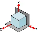
Geometry tells us that three points are required to define a plane. This is the "3" in 3-2-1. So, three specific points are used to define the first plane. Fewer than three points cannot define a plane, and in the real world dimensional tolerances mean that four or more points will not be coplanar. A real-world, less than ideally perfect part placed on four or more reference points will, in fact, rest on only three of the points due to its less than perfect surface. Different parts may rest on different combinations of three points, resulting in variation between finished parts. A stool can be used to illustrate this concept. A two-legged stool would certainly be unstable. A three-legged stool sits rock-solid. A four-legged stool is often found to rock. In the illustration, a three dimensional part, represented by a cube, is placed on a datum plane defined by three support points. The part’s six degrees of freedom have now been reduced to three. It can still move along the X or Y axes, and it can still be rotated about the Z axis. (The part cannot move along the Z axis because it is held against the plane by clamping force.
TIPS
- Use the largest surface of the part for the first ("primary") reference plane.
- Position the three support points as far apart as possible.
- If more than three support points are required to prevent deflection, make the additional points adjustable.
Second Plane
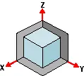
A second plane, if it is perpendicular to the first, can be defined by two points, the "2" in 3-2-1. The part is now constrained to one degree of freedom: movement along the Y axis. (The part cannot move along the X or Z axes because it is held against the planes by clamping force.)
TIPS
- Use the largest surface of the part for the first ("primary") reference plane.
- Position the three support points as far apart as possible.
- If more than three support points are required to prevent deflection, make the additional points adjustable.
Third Plane
A third plane, if it is perpendicular to both of the first two planes, can be defined by one point, the "1" in 3-2-1. The part is now entirely constrained. It cannot move along or rotate about the X, Y, or Z axes. (Remember that the part is held against each of the three planes by clamping force.)
TIPS
- If more than one support point is required to prevent deflection, make the additional points adjustable.
Body planes
Body planes are the reference planes in automotive car. These planes are used to define the GD&T of all car parts in an automotive domain.
Body planes are 3 mutually perpendicular imaginary planes. These are generally considered to be present at the driver position or sometimes at the engine location or at the front end of the car, depending on the customer.
The measurements from the body planes to the parts are called as bodyline dimensions
These body planes are called as
- FOL Front O Line
- COL Centre O Line
- BOL Body O Line
- The Measurement along FOL or X axis is called as F/A Front After
- The Measurement along COL or Y axis is called as C/C Cross Car
- The Measurement along BOL or Z axis is called as U/D Up Down
Bodyline dimensions are essential for the reasons stated below,
- It defines the exact position of each product in the vehicle w.r.t, a fixed origin
- It ensures flawless design for the assembly
- While designing lines all the designs are carried out relative to the bodyline, viz., fixtures, turn tables etc.,
- It assists in easy location of different parts in a vehicle
- It aims in creating a standardized system
- It assists in quality checks.