Week 2:- BiW Fixture Basics Challenge
Question 1. What is the process of project execution activity?
Answer 1. Project execution activity is a general activity which is involved in BIW fixture & Tooling. It is a starting phase of every project and it starts with a basic requirements like a request for quotation (RFQ), which we initially receive from the customer.
The below chart, shows series of project activities-
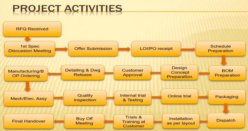
- RFQ (Request For Quotation)-
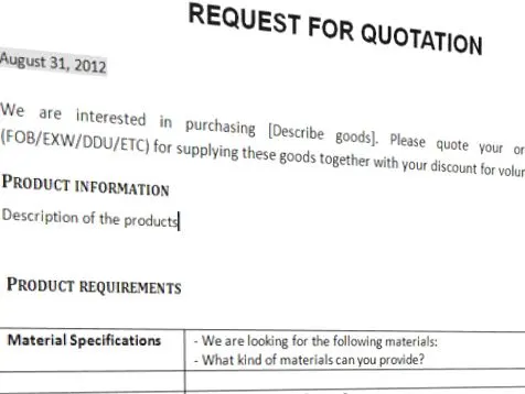
A request for quotation (RFQ) is a business process in which a company or public entity requests a quote from a supplier for the purchase of specific products or service. An RFQ generally means the same thing as call for bids (CFB) and Invitation for bid (IFB).
In this where customer gives the requirement/specification in detail for the given projects in the form of data or documents.
An RfQ typically involves more than the price per item. Information like payment terms, quality level per item or contract length may be requested during the bidding process.
Sample Image of an RFQ `darr`
- 1st Spec, Discussion Meeting-
After the RFQ received, the Technical offer, the commercial offer and the time duration of the project will be discussed and prepared from outside.
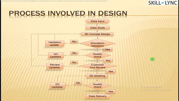
In this time required for data study, 3D design concept, and Simulation validation, quality check, 2D drawing release, Bought outs, manufacturing, Assembly, installation & commissioning will be discussed and prepared in the technical offer.
Based on technical offer, commercial offer will be finalized.
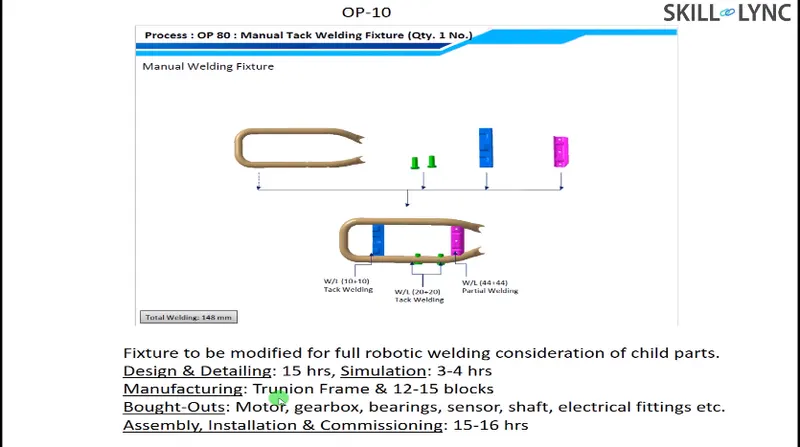
Sample Image of a Technical Offer`darr`
Offer Submission-
After the finalization in the meeting, the offer will be submitted to customer. The customer will also arrange to get an offer from other suppliers.
Based on the technical, cost, quantity, standard and name in the industries the customer will finalized the offer.
LOI(Letter of Intent)/PO(Purchase Order) Receipt-
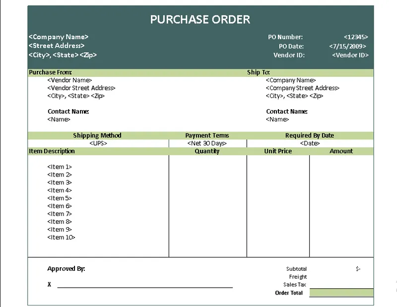
A purchase order (PO) is a commercial document and first official offer issued by a buyer to a seller indicating types, quantities, and agreed prices for products or services. After the offer has been finalized, the customer will release the LOI/PO(purchase order).
Once PO is realese we have to start the work.
After PO from the customer we have to prepare the schedule.
Sample Image of a Puarchase Order `darr`
Schedule Preparation-
Once the PO released from the customer, we will be working on preparation of schedule which should be matched to our planned commitment in the technical offer / customer required time.
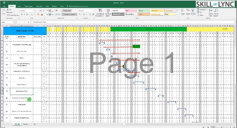
Schedule preparation is nothing but dividing the different activities like kick off meeting, design data study, DAP, Simulate, quality check, 2D detailing, Drawing check, release of BOM, Manufacturing, Bought outs of electrical & mechanical components, assembly of fixture, paint, trial run out, installation and commissioning at customer end etc,
These activities will be traced in the schedule preparation chart.
The date wise schedule should be matched the commited date. Otherwise have to revised the schedule and prepare accordingly by discussing in the meetings.
Schedule Sheet`darr`
BOM(Bill of Material) Preparation-
A bill of materials (BOM) is a centralized source of information used to manufacture a product. It is a list of the items needed to create a product as well as the instructions on how to assemble that product. Manufacturers that build products start the assembly process by creating a BOM.
Sample Image of a BOM(Bill of material) `darr`
DESIGN CONCEPT PREPARATION-
Before design concept, we have to study the data of consumer requirement throughly which is carried out in design data study activities.
During design data study, we will be proceed with rough sketches to get a flow while designing concepts.
The concept preparation would include the process like load act on panels, clamping process, which spot should be welded first, travel of the gun.
The weld gun should not collapse while travelling, so by considering this have to make a concept preparation.
To avoid collapses of weldgun or robots during travelling, spot plan will be done at initial stage.
In design concept preparation, the design of the layout is prepared at very initial level which gives the information of placements of robots and fixtures.
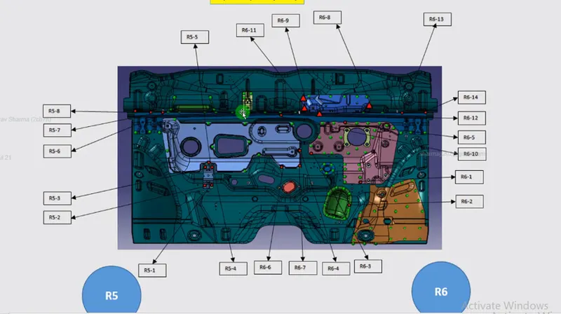
Spot plan clears us that how much robots are to be used and the sequence of the spot will be decided along with which robot will be cover certain spot places.
Also cycle time should be considered while preparing concept design.
To calculate the cycle time we should go to cycle time study.
Cycle time study includes : Minimum per shifts, number of shifts, number of days per year, number of components per year, total number of minutes, efficiency, total number of seconds, taik time seconds, Average time per spot, total number of spot, number of robots placed.
From the cycle time study we can get time taken per spot, time taken for single component, efficiency of production.
If the efficiency is not satisfied we have to do some reconsideration in the design.
Customer Approval-
It is also known as design approval process (DAP).
After design concepts the customer will review the design concepts.
If the design need to be made simple or some other correction needs to be done in concept design will be discussed and after meeting the requirement of customer, they will give approval to the design to go on with furthur activities.
Detailing and Drawing release-
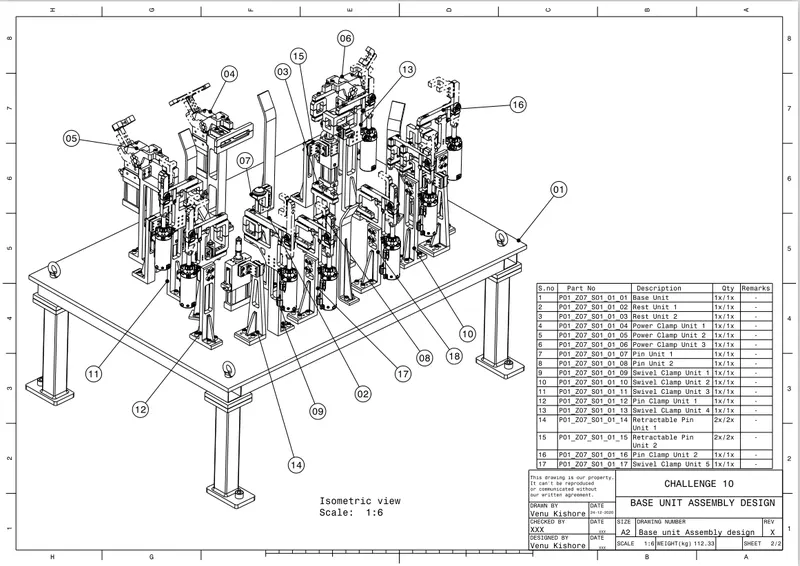
Once the customer approved the process, the detailing of the fixture parts which is to be manufactured has been done with giving appropriate dimensions and GD&T symbols.
All the dimensions which is necessary for manufacturing should be included with GD&T in the drawings before releasing the drawing to the manufacturing team.
Sample Image of a Drawing `darr`
Manufacturing / BOP Ordering-
The mechanical & electrical parts like sensors, cylinders, etc., which needs for fixture are ordered as per design specifications.
Mechanical/Electrical Assembly-
After the materials ordered received to our end. The quality team will check the working conditions and technical specifications, which meets our requirement.
After the quality check the mechanical & the electrical parts are assembled as per design.
Quality Inspection-
After the assembly again the quality check is done.
In this all dimensions, positional accuracy, coordinates are checked using CMM.
Image of Fixture Inspection using CMM `darr`
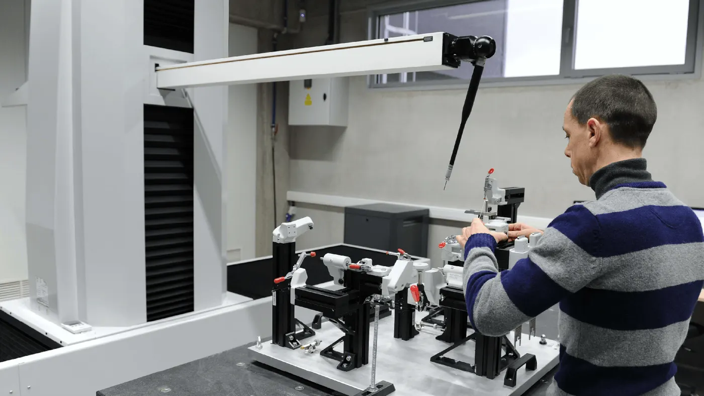
Internal trial-
After QC check internal trials are made to check the operation of the fixure.
It is a first trial taken inhouse, so we will see by putting the assembly in the fixture whether the seating of assembly/panel suited correctly, whether the clamping operation are done properly, also whether the pins are getting into the holes,etc.
Online Trial-
The trial will done in automatic made through control panel.
The process sequence of operations is checked as by the designed way.
Packaging-
To avoid damage occur in fixtures while transportation which may also leads to affect the aesthetic look & proper function of fixture packaging has been done.
After the trials taken have to get the QC confirmation whether the panels met the standards/specs given by customer also whether the fixture meets the customer standards.
After approval of QC, packaging is been done as per standards certain companies follow certain packaging standards, so the packaging should be one as per customer standards.
Dispatch-
After the fixture has been packed for delivery as per standards.
Its been dispatched to the customer.
Installation as per layout-
As we discussed in design concept preparation, the design of the layout are been prepared at very initial level which gives the information of placements of robots and fixtures.
According to the design the installation & commissioning team will install the fixtures.
Trials & Training at Customer-
Production trails will be taken at customer end.
During technical offer we will be confirmed that n-number of assemblies will be produced within 8hrs/12hrs shifts.
So in customer trial we have to achieve the confirmed quantity of assemblies.
Once it is achieved, training will be given to the operator, staffs, engineers who involved in this process.
The sequence of working process by the fixture will be explained in detail.
The check points which has to be done after placing the panels into the fixture will be made clear to them.
Buy off Meeting
After trials and training at customer end, buy off meeting will be held.
In this meeting customer will give reviews about the fixtures, sometimes customer may need/feels better to do some addition work also. It will be discussed and finalize in the meeting.
Final Handover-
The fixture and the documents supports the fixtures/production will be handed over.
Documents like poka yoke documents, clamp validation document, ergo sheets, BOM, charts will be delivered and handed over to customers.
Documents will play a vital role in industry, we should always have a proof for our work done. The sequence of quality of work will be seen through the documents.
Every automobile industries will follow some standards to maintain documents as per ISO,IATF.
Now every automobile industries/vendors/suppliers are maintaining the documents as per IATF (International Automotive Task Force).
IAFT - The International automotive task force is a group of automotive manufactures which aims at providing improved quality products to automotive customers worldwide.
Question 2. What are the types of joining processes?
Answer 2. Joining comprises a large number of processes used to assemble individual parts into a larger, more complex component or assembly.
The individual parts of a component meet at the joints.
Joints transmits or distribute forces generated during service from one part to the other parts of the assembly.
Types of joining Process-
The durability & performance of any structure is largely depend on the quality & the design of the component joints.
Whole structure cannot be made in one piece.
Two fundamental options for joining materials & components are,
- Metallurgical joining.
- Mechanical joining.
- Chemical joining.
- Metallurgical joining- Metallurgical joining includes fusion welding, pressure welding and brazing/soldering which use different energies.
- Fusion welding
- Pressure welding
- Brazing/soldering
Fusion welding- Fusion welding is a process that uses heat to join or fuse two or more materials by heating them to melting point.
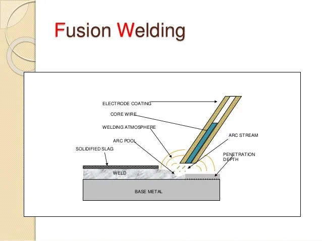
Classification of Fusion Welding-
- Arc Welding.
- Gas Welding.
- Thermit welding
- Arc Welding- Arc welding is a type of welding process using an electric arc to create heat to melt and join metals. A power supply creates an electric arc between a consumable or non-consumable electrode and the base material using either direct (DC) or alternating (AC) currents.
Types of Arc Welding:
- MIG Welding
- TIG Welding
- Shielded Metal Arc Welding
- Plasma Arc Welding
- Submerged Arc Welding
- Electro slag Arc Welding
- Atomic Hydrogen Welding
- MIG Welding- MIG welding is an arc welding process in which a continuous solid wire electrode is fed through a welding gun and into the weld pool, joining the two base materials together. A shielding gas is also sent through the welding gun and protects the weld pool from contamination. In fact, MIG stands for metal inert gas. The technical name for it is gas metal arc welding (or GMAW), and the slang name for it is wire welding.
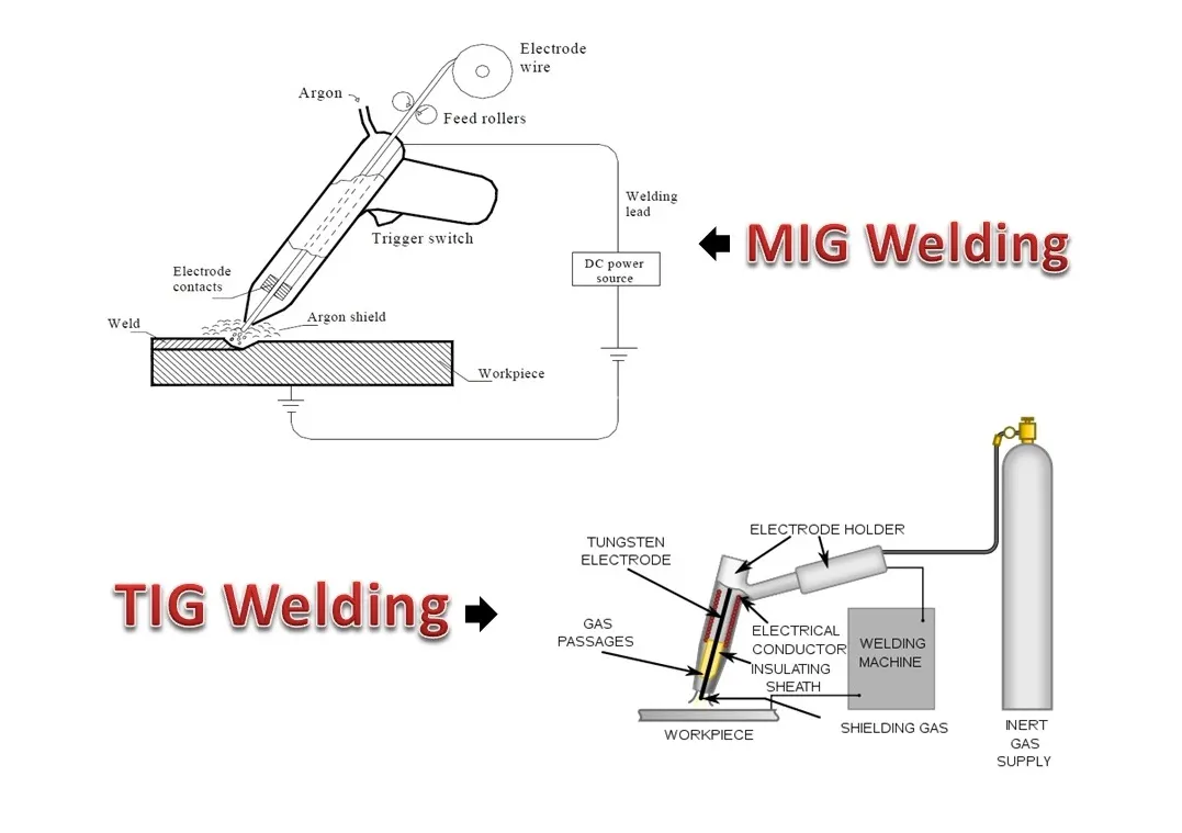
- TIG Welding- Gas tungsten arc welding, also known as tungsten inert gas welding, is an arc welding process that uses a non-consumable tungsten electrode to produce the weld. The weld area and electrode are protected from oxidation or other atmospheric contamination by an inert shielding gas.
- Shielded Metal Arc Welding- Shielded Metal Arc Welding is a manual arc welding process that uses a consumable electrode covered with a flux to lay the weld.
An electric current, in the form of either alternating current or direct current from a welding power supply, is used to form an electric arc between the electrode and the metals to be joined. The workpiece and the electrode melts forming a pool of molten metal (weld pool) that cools to form a joint.
- Plasma Arc Welding- Plasma arc welding is an arc welding process similar to gas tungsten arc welding. The electric arc is formed between an electrode and the workpiece. The key difference from GTAW is that in PAW, the electrode is positioned within the body of the torch, so the plasma arc is separated from the shielding gas envelope.
- Submerged Arc Welding- Submerged Arc Welding (SAW) is a joining process that involves the formation of an electric arc between a continuously fed electrode and the workpiece to be welded. A blanket of powdered flux surrounds and covers the arc and, when molten, provides electrical conduction between the metal to be joined and the electrode.
- Electro slag Arc Welding- Electroslag Welding is a welding process, in which the heat is generated by an electric current passing between the consumable electrode (filler metal) and the work piece through a molten slag covering the weld surface.
Prior to welding the gap between the two work pieces is filled with a welding flux. Electroslag Welding is initiated by an arc between the electrode and the work piece (or starting plate). Heat, generated by the arc, melts the fluxing powder and forms molten slag. The slag, having low electric conductivity, is maintained in liquid state due to heat produced by the electric current.
The slag reaches a temperature of about 3500°F (1930°C). This temperature is sufficient for melting the consumable electrode and work piece edges. Metal droplets fall to the weld pool and join the work pieces.
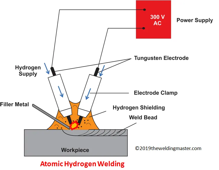
- Atomic Hydrogen Welding- Atomic hydrogen welding is an arc welding process that uses an arc between two tungsten electrodes in a shielding atmosphere of hydrogen. The process was invented by Irving Langmuir in the course of his studies of atomic hydrogen.
2. Gas Welding- Gas welding is a welding process that melts and joins metals by heating them with a flame caused by a reaction of fuel gas and oxygen.
- Metal 2mm to 50mm thick are welded by gas welding.
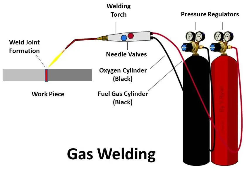
Types of gas welding-
- Oxy-acetylene gas welding
- Oxy-gasoline gas welding
- MAPP gas welding
- Butane or propane welding
- Hydrogen gas welding
a. Oxy-acetylene Welding- In this type of welding, oxy-acetylene welding applies a mixture of acetylene gas and oxygen gas to supply welding torches. Oxy-acetylene welding is the most generally used gas welding type. This gas mixture provides the highest flame temperature of available fuel gases.
Although acetylene is generally the most expensive of all fuel gases. Acetylene is a volatile gas and requires specific handling and storage procedures.
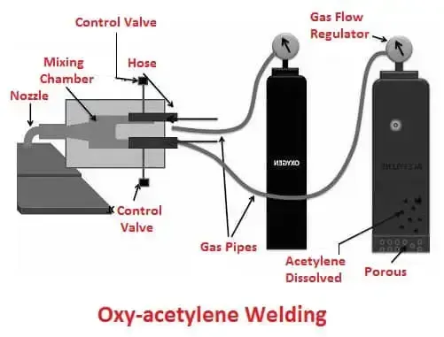
b. Oxy-gasoline Welding- The pressurized gasoline is used as welding fuel where construction costs are an issue, especially in places where acetylene canisters are not available. Gasoline torches may be more useful than acetylene for torch-cutting thick steel plates.
c. MAPP Gas Welding- In this, gas welding stands for Methylacetylene-propadiene-petroleum gas welding. The (MAPP) is a gas mixture that is much more inert than other gas mixtures, making it safe to use and store for beginner and recreational welders.
MAPP can also be used at extremely high pressures, it is used in high-volume cutting operations.
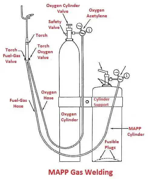
d. Butane or Propane Welding- These are similar gases that can be used as separate as fuel gases or combined together. Butane and propane have lower flame temperatures as compared to acetylene but are less costly and easier to transport.
Propane torches are used more often for soldering, bending, and heating. Propane needs a different type of torch tip than the injector tip because it is a heavy gas.
e. Hydrogen gas Welding- The hydrogen can be utilised at higher pressures than other fuel gases, making it particularly useful for underwater welding processes.
Some hydrogen welding equipment performs electrolysis by splitting the water into hydrogen and oxygen used in the welding process. Such electrolysis is often used for small torches, These are used in the jewellery making process.
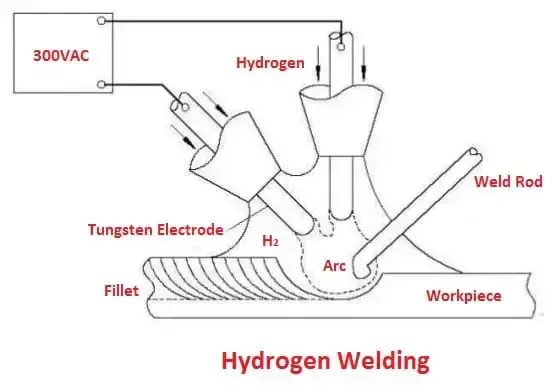
3. Thermit welding- Thermit welding, is a welding process that employs molten metal to permanently join the conductors. The process employs an exothermic reaction of a thermite composition to heat the metal, and requires no external source of heat or current.
Thermit Welding is mainly used for joining steel parts, therefore common thermit is composed from iron oxide (78%) and aluminum powder (22%).
The proportion 78-22 is determined by the chemical reaction of combustion of aluminum:
8Al + Fe3O4 = 9Fe + 4Al2O3
The combustion reaction products (iron and aluminum oxide) heat up to 4500°F (2500°C). Liquid iron fills the sand or (ceramics) mold. built around the welded parts, the slag (aluminum oxide), floating up , is then removed from the weld surface.
Pressure Welding-
Pressure welding uses friction or explosion to heat the joining section of metal work pieces and join them under pressure. The process is also called solid-state welding. Pressure welding is a generic term for welding methods that weld work pieces by applying mechanical pressure on the joining section (weld joint).
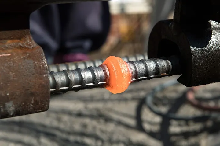
The use of mechanical pressure allows numerical control of the process. Pressure welding has been used widely in FA (factory automation). Major methods include gas pressure welding, friction welding, resistance welding, diffusion welding, ultrasonic welding, and explosion welding.
Types of Pressure welding process, They are
- Resistance Welding
- Diffusion welding (DFW)
- Friction welding (FRW)
- Ultrasonic welding (USW)
- Cold Pressure Welding
- Forge welding
- Explosion welding (EXW)
Resistance Welding-
Types of Resistance welding are,
- Resistance spot welding.
- Resistance projection welding.
- Resistance seam welding.
- Butt welding.
- Flash Butt welding.
Resistance spot welding-
Weld materials are held together from above and below with copper electrodes for energization connected to the welding power supply. When a current passes through the section to be welded, the heat generated by electrical resistance (Joule heat) melts and joints the materials. In FA (factory automation), automatic resistant spot welding machines have been used widely in joining processes on Electrodes weld material manufacturing lines.
Seam welding, which uses a series of overlapping weld spots, and projection welding, which causes concentrated resistance heat on projections created on the joining surface of one material, are variations of resistant spot welding.
Resistance projection welding-
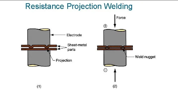
Projection welding is a resistance welding process for joining metal components or sheets with embossments by directly applying opposing forces with electrodes.
This method is used for welding nuts/bolts to steel plates. Electrodes for resistant spot welding are applied to the projection(s) provided on one of the base materials.
Heat is concentrated on the projection(s) to soften the material and the welding starts. As the welding proceeds, the spot(s) becomes larger. Although this decreases the current density, the electrical resistance is increased by the raised temperature, which maintains high heat generation to allow welding. Consequently, the weld has high quality as compared to welding without using projections.
Resistance seam welding-
Weld materials are held from above and below with circular electrodes. A current is passed while the electrodes are rotated, and the heat generated by electrical resistance joins the weld materials continuously. The method is also called lap seam welding.
Making a line of overlapping spot welds ensures leak tightness. This is cost effective because the welding speed is fast and no gas is used.
Since sparks are not produced during welding, there are no safety problems.
Diffusion Welding-
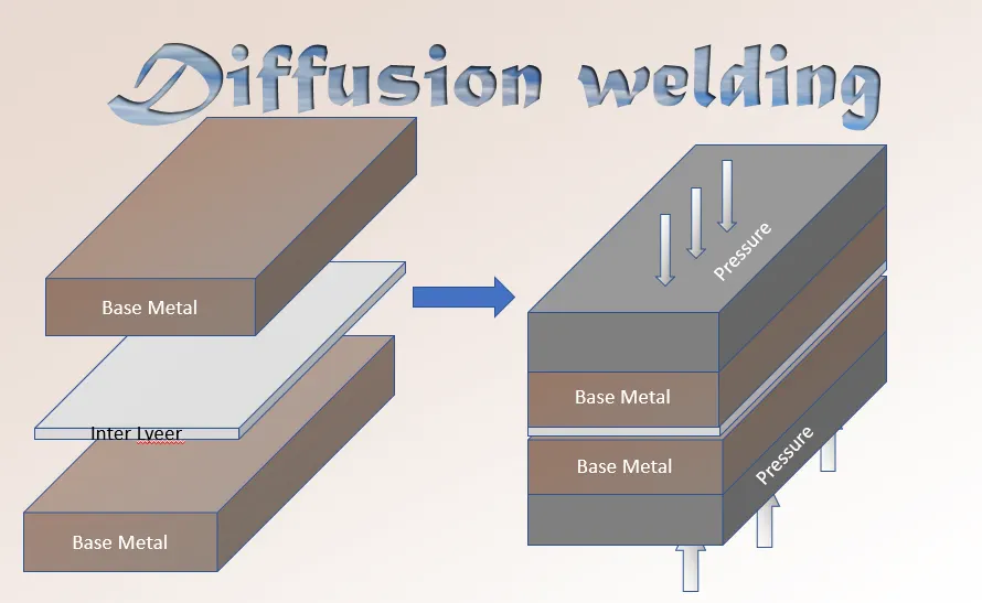
- Diffusion Welding is a solid state welding process, in which pressure applied to two work pieces with carefully cleaned surfaces and at an elevated temperature below the melting point of the metals. Bonding of the materials is a result of mutual diffusion of their interface atoms.
- In order to keep the bonded surfaces clean from oxides and other air contaminations, the process is often conducted in vacuum.
- No appreciable deformation of the work pieces occurs in Diffusion Welding.
Diffusion Welding is often referred more commonly as solid state welding process. - Diffusion Welding is able to bond dissimilar metals, which are difficult to weld by other welding processes:
- Steel to tungsten;
- Steel to niobium;
- Stainless steel to titanium;
- Gold to copper alloys.
- Diffusion Welding is used in aerospace and rocketry industries, electronics, nuclear applications, manufacturing composite material.
Friction Welding-
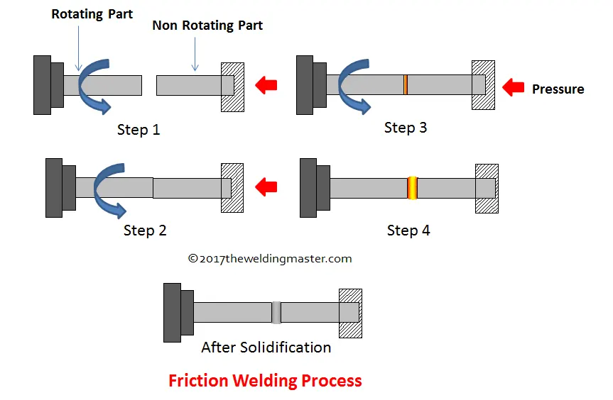
Friction Welding is a solid state welding process, in which two cylindrical parts are brought in contact by a friction pressure when one of them rotates. Friction between the parts results in heating their ends. Forge pressure is then applied to the pieces providing formation of the joint.
Carbon steels, alloy steels, tool & die steels, adequate steels, aluminium alloys, copper alloys, magnesium alloys, nickel alloys, titanium alloys may be joined by Friction Welding.
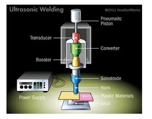
Ultrasonic Welding (USW)
- Ultrasonic Welding is a solid state welding process, in which two work pieces are bonded as a result of a pressure exerted to the welded parts combined with application of high frequency acoustic vibration (ultrasonic).
Ultrasonic vibration causes friction between the parts, which results in a closer contact between the two surfaces with simultaneous local heating of the contact area. Interatomic bonds, formed under these conditions, provide strong joint.
Ultrasonic cycle takes about 1 sec. The frequency of acoustic vibrations is in the range 20 to 70 KHz.
Thickness of the welded parts is limited by the power of the ultrasonic generator.
Cold Welding (CW)
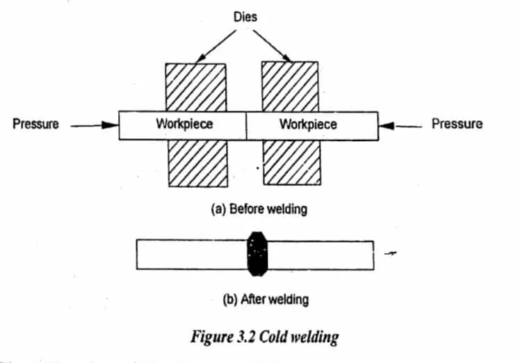
- Cold Welding is a solid state welding process, in which two work pieces are joined together at room temperature and under a pressure, causing a substantial deformation of the welded parts and providing an intimate contact between the welded surfaces.
- As a result of the deformation, the oxide film covering the welded parts breaks up, and clean metal surfaces reveal. Intimate contact between these pure surfaces provide a strong and defectless bonding.
- Aluminium alloys, carbon alloys, low carbon steels, nickel alloys, and other ductile metals may be welded by Cold Welding.
- Cold Welding is widely used for manufacturing bi-metal steel - aluminum alloy strips, for cladding of aluminum alloy strips by other aluminum alloys or pure aluminum (corrosion protection coating). Bi-metal strips are produced by rolling technology. Presses are also used for Cold Welding.Cold Welding may be easily automated.
Forge Welding (FOW)
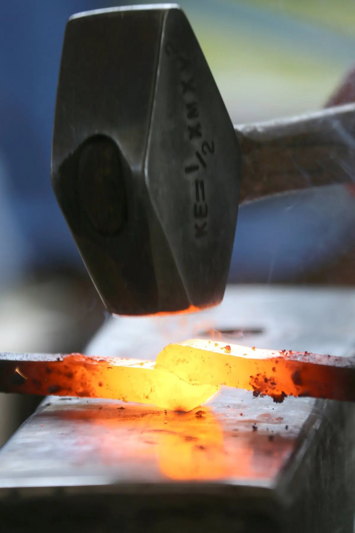
- Forge Welding is a solid state welding process, in which low carbon steel parts are heated to about 1800°F (1000°C) and then forged (hammered).
Prior to Forge Welding, the parts are scarfed in order to prevent entrapment of oxides in the joint. - Forge Welding is used in general blacksmith shops and for manufacturing metal art pieces and welded tubes.
Explosive Welding (EXW)
- Explosive Welding is a solid state welding process, in which welded parts (plates) are metallurgically bonded as a result of oblique impact pressure exerted on them by a controlled detonation of an explosive charge.
- One of the welded parts (base plate) is rested on an anvil, the second part (flyer plate) is located above the base plate with an angled or constant interface clearance.
- Explosive charge is placed on the flyer plate. Detonation starts at an edge of the plate and propagates at high velocity along the plate.
The maximum detonation velocity is about 120% of the material sonic velocity. - The slags (oxides, nitrides and other contaminants) are expelled by the jet created just ahead of the bonding front.
- Most of the commercial metals and alloys may be bonded (welded) by Explosive Welding.
Brazing AND Soldering-
Brazing-
Brazing is a method of welding that uses filler materials with high melting points. Torch brazing uses a normal gas welding torch as a heat source, and induction heating brazing uses high-frequency induction heating as a heat source.
Another method is controlled atmosphere brazing (furnace brazing) that is done inside a vacuum furnace without using flux by heating and cooling the base material and filler material.
These welding methods are used for non-oxidizing brazing of stainless steel and for the automation of joining titanium and ceramic workpieces.
In recent years, another brazing technique known as laser brazing has attracted a lot of attention.
Laser brazing uses light energy (laser) to melt a wire-shaped filler material supplied between base materials to join them. Since this process rarely melts the base materials, thermal deformation is minimized.
This allows lightweight and highly rigid joining without affecting the product design.
There are different methods/techniques in brazing. They are
- Furnace brazing - uses a furnace for heating the work pieces.
- Vacuum brazing - is a type of furnace brazing, in which heating is performed in vacuum.
- Induction brazing - utilizes alternating electro-magnetic field of high frequency for heating the work pieces together with the flux and the filler metal placed in the joint region.
- Resistance brazing - uses a heat generated by an electric current flowing through the work pieces.
- Dip brazing - is a brazing method, in which the work pieces together with the filler metal are immersed into a bath with a molten salt. The filler material melts and flows into the joint.
- Infrared brazing - utilizes a heat of a high power infrared lamp.
Soldering-
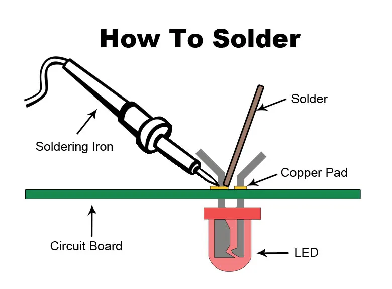
Soldering is a method of welding that uses filler materials with low melting points.
Normal soldering uses heat produced by an electric current such as a soldering iron.
Light beam soldering has been adopted for the production of electronic components in FA (factory automation).
It uses a reflector to converge the light generated from a large output light source, focuses the light on the weld area and melts the solder with the energy of the light.
Since the process uses solders (soft filler materials) with low melting temperatures and allows the use of robots for precise joining, it is useful for assembly automation and mass-production of heat-sensitive electronic components.
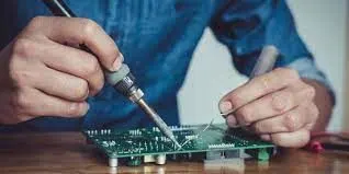
There are different types of soldering methods. They are-
- Hand soldering - Hand soldering is used in repair works and for low volume production.
- Iron soldering - utilizes a heat generated by a soldering iron.
- Torch soldering - utilizes a heat of the flame from a torch. The torch mixes a fuel gas with oxygen or air in the proper ratio and flow rate, providing combustion process at a required temperature. The torch flame is directed to the work pieces with a flux applied on their surfaces. When the work pieces are heated to a required temperature, solder is fed into the joint region. The solder melts and flows to the gap between the joined parts.
- Wave soldering - The method uses a tank full with a molten solder. The solder is pumped, and its flow forms a wave of a predetermined height. The printed circuit boards pass over the wave touching it with their lower sides.The method is used for soldering through-hole components on printed circuit boards.
- Reflow soldering - In this method a solder paste (a mix of solder and flux particles) is applied onto the surface of the parts to be joined and then are heated to a temperature above the melting point of the solder. The process is conducted in a continuous furnace, having different zones: preheating, soaking, reflow and cooling. The joint forms when the solder cools down and solidifies in the cooling zone of the furnace.
Mechanical joining-
Mechanical joining includes bolting, riveting, caulking, shrink fitting, Hemming, Seaming and folding, all of which join work pieces by using mechanical energy.
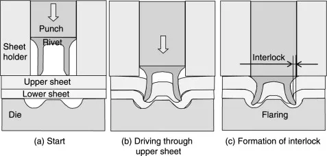
- Self Piercing Riveting-
- It is a high speed mechanical fastening process for point joining sheet material, typically steels and aluminium alloys.
- It is a single step technique generally using a semitubular rivet to clinch the sheets in a mechanical joint.
- As the name suggests pre-drilled holes are not required, allowing the joint to be made rapidly in one operation.
Hemming & seaming process-
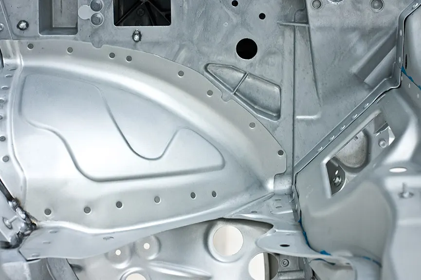
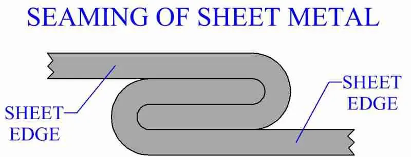
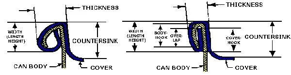
- Hemming & seaming are two similar metal working process in which a sheet metal edge is rolled over onto itself.
- Hemming is a process in which the edge is rolled flush to itself, while a seam joins the edge of two materials.
Hemming Image `darr`
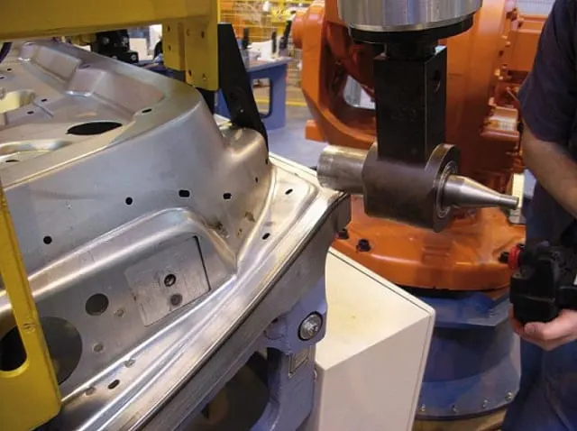
Seaming Image `darr`
Bolting-
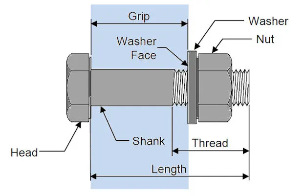
Bolted joints are one of the most common elements in construction and machine design. They consist of fasteners that capture and join other parts, and are secured with the mating of screw threads.
There are two main types of bolted joint designs: tension joints and shear joints.
In the tension joint, the bolt and clamped components of the joint are designed to transfer an applied tension load through the joint by way of the clamped components by the design of a proper balance of joint and bolt stiffness. The joint should be designed such that the clamp load is never overcome by the external tension forces acting to separate the joint. If the external tension forces overcome the clamp load (bolt preload) the clamped joint components will separate, allowing relative motion of the components.
The second type of bolted joint transfers the applied load in shear of the bolt shank and relies on the shear strength of the bolt. Tension loads on such a joint are only incidental. A preload is still applied but consideration of joint flexibility is not as critical as in the case where loads are transmitted through the joint in tension. Other such shear joints do not employ a preload on the bolt as they are designed to allow rotation of the joint about the bolt, but use other methods of maintaining bolt/joint integrity. Joints that allow rotation include clevis linkages, and rely on a locking mechanism (like lock washers, thread adhesives, and lock nuts).
Proper joint design and bolt preload provides useful properties-
- For cyclic tension loads, the fastener is not subjected to the full amplitude of the load; as a result, the fastener's fatigue life is increased or—if the material exhibits an endurance limit its life extends indefinitely.
- As long as the external tension loads on a joint do not exceed the clamp load, the fastener is not subjected to motion that would loosen it, obviating the need for locking mechanisms. (Questionable under Vibration Inputs.)
- For the shear joint, a proper clamping force on the joint components prevents relative motion of those components and the fretting wear of those that could result in the development of fatigue cracks.
- In both the tension and shear joint design cases, some level of tension preload in the bolt and resulting compression preload in the clamped components is essential to the joint integrity. The preload target can be achieved by a variety of methods: applying a measured torque to the bolt, measuring bolt extension, heating to expand the bolt then turning the nut down, torquing the bolt to the yield point, testing ultrasonically, or by applying a certain number of degrees of relative rotation of the threaded components. Each method has a range of uncertainties associated with it, some of which are very substantial.
- Shrink fitting-
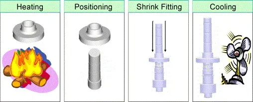
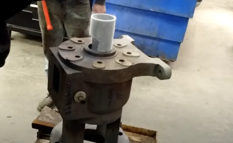
Shrink-fitting is a technique in which an interference fit is achieved by a relative size change after assembly. This is usually achieved by heating or cooling one component before assembly and allowing it to return to the ambient temperature after assembly, employing the phenomenon of thermal expansion to make a joint. For example, the thermal expansion of a piece of a metallic drainpipe allows a builder to fit the cooler piece to it. As the adjoined pieces reach the same temperature, the joint becomes strained and stronger.
- Other examples are the fitting of a wrought iron tyre around the rim of a wooden cart wheel by a wheel wright, or of a steel tyre to the wheel of a railway engine or rolling stock. In both cases the tyre will be heated and expands to slightly greater than the wheel's diameter, and is fitted around it. After cooling, the tyre contracts, binding tightly in place. A common method used in industry is the use of induction shrink fitting which refers to the use of induction heating technology to pre-heat metal components between 150˚C and 300˚C thereby causing them to expand and allow for the insertion or removal of another component. Other methods of shrink-fitting include compression shrink fitting, which uses a cryogen such as liquid nitrogen to cool the insert, and shape memory coupling, which is achieved by means of a phase transition.
Chemical joining-
Chemical joining includes Adhesive bondings.
Adhesive Bonding-
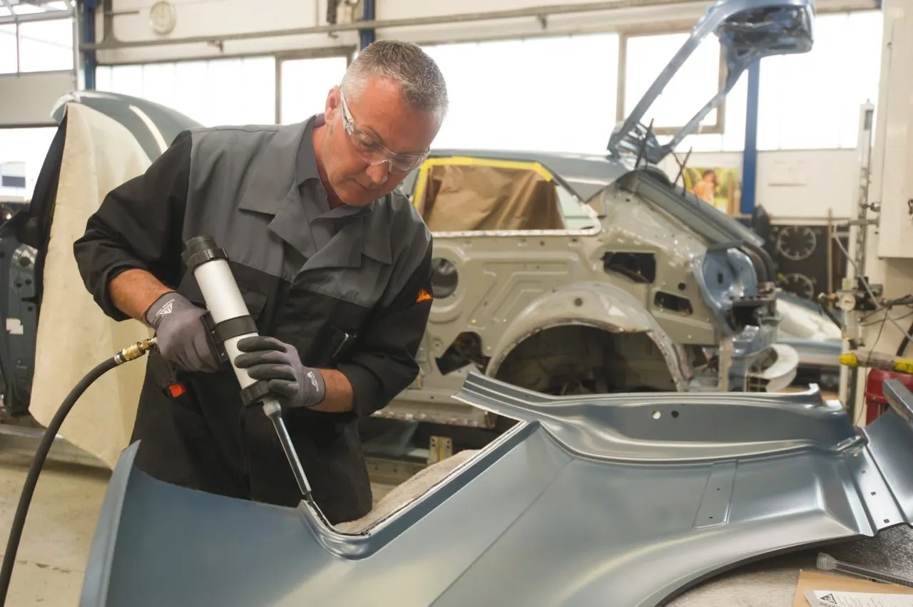
Adhesive bonding is used to fasten two surfaces together usually producing a smooth bond.
The joining technique involves glues, epoxies, or various plastic agents that bond by evaporation of a solvent or by curing a bonding agent with heat,pressure or time.
Adhesive bonding (also referred to as gluing or glue bonding) describes a wafer bonding technique with applying an intermediate layer to connect substrates of different types of materials. Those connections produced can be soluble or insoluble. The commercially available adhesive can be organic or inorganic and is deposited on one or both substrate surfaces. Adhesives, especially the well-established SU-8, and benzocyclobutane(BCB), are specialized for MEMS or electronic component production.
The procedure enables bonding temperatures from 1000 °C down to room temperature. The most important process parameters for achieving a high bonding strength are:
- adhesive material
- coating thickness
- bonding temperature
- processing time
- chamber pressure
- tool pressure
Adhesive bonding has the advantage of relatively low bonding temperature as well as the absence of electric voltage and current. Based on the fact that the wafers are not in direct contact, this procedure enables the use of different substrates, e.g. silicon, glass, metals and other semiconductor materials. A drawback is that small structures become wider during patterning which hampers the production of an accurate intermediate layer with tight dimension control. Further, the possibility of corrosion due to out-gassed products, thermal instability and penetration of moisture limits the reliability of the bonding process. Another disadvantage is the missing possibility of hermetically sealed encapsulation due to higher permeability of gas and water molecules while using organic adhesives.
Question 3. What is resistance welding & its application in automotive sector?
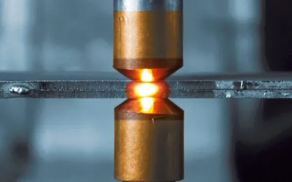
Answer 3. Resistance Welding - Resistance Welding is a welding process, in which work pieces are welded due to a combination of a pressure applied to them and a localized heat generated by a high electric current flowing through the contact area of the weld.
Heat produced by the current is sufficient for local melting of the work piece at the contact point and formation of small weld pool. The molten metal is then solidifies under a pressure and joins the pieces. Time of the process and values of the pressure and flowing current, required for formation of reliable joint, are determined by dimensions of the electrodes and the work piece metal type.
AC electric current (up to 100 000 A) is supplied through copper electrodes connected to the secondary coil of a welding transformer.
The following metals may be welded by Resistance Welding:
Low carbon steels - the widest application of Resistance Welding
Aluminum alloys
Medium carbon steels, high carbon steels and Alloy steels (may be welded, but the weld is brittle)
Resistance Welding (RW) is used for joining vehicle body parts, fuel tanks, domestic radiators, pipes of gas oil and water pipelines, wire ends, turbine blades, railway tracks.
Advantages of Resistance Welding-
- High welding rates;
- Low fumes;
- Cost effectiveness;
- Easy automation;
- No filler materials are required;
- Low distortions.
Disadvantages of Resistance Welding-
- High equipment cost;
- Low strength of discontinuous welds;
- Thickness of welded sheets is limited - up to 1/4” (6 mm);
The most popular methods of Resistance Welding are-
- Spot Welding (RSW)
- Projection Welding (FW)
- Resistance Butt Welding (UW)
- Seam Welding (RSEW)
Resistance Spot Welding (RSW)-
The resistance spot welding process use two copper alloy electrode to concentrate weld current and forced between work to be welded. Produce coalescence in one spot for heat generated from resistance to the electrical current through work piece held together under pressure by electrode. It process usually the thickness range of sheet metal is 0.5 to 3.0 mm. the small spot is quickly heated until melting point, in this reason a nugget of welded metal after power supply removed. When the current is applied too long, which result in molten metal become expelled as welded splash (or) can be made a have right through the material become welded. In this spot welding used for welding steel sheet metal.
Working principle of Resistance Spot Welding-
The weld sheet metal is cleaned together and that are free from dirt, oxide, grease and oxides.
The electrode tip will be cleaned it should be conduct current; otherwise the electric resistance is generated between work piece and electrode.
Both side of plate, the electrode are stick. When the pressures is created to the electrodes and maintain a particular time period is known as sequence of time for before starting of weld.
Now, the current is passed through electrode. The weld time is, time of application of time taken. At the weld time during the process pressure to be maintained and weld current range of 3000 A to 100000 A, it passed to electrode at time of 0.1 to 0.5 sec. The step down transformer controls the magnitude of high current possible.
The current is passed one electrode to another electrode through the work piece, a small area contact between the work pieces. This spot is known as resistance spot. The spot generate the temperature and increase above 900⁰
After weld time completed, the current is shout down and pressure will be maintain a particular brief of time is called as hold time. So the heat metal solidified and form of weld hugest.
After brief time the pressure released, then work piece is removed.
Now water is supplied to the electrode because of avoid overheating of electrode. In this welding process, set proper welding current and time before welding.
Advantages of Spot Welding-
- Spot welding is quick and easy.
- There is no need to use any fluxes or filler metal to create a join by spot welding, and there is no dangerous open flame. Spot welding can be performed without any special skill.
- Automated machines can spot weld in factories to speed up production. The machines used in car factories produce as many as 200 spot welds in six seconds.
- Spot welding can be used to join many different metals, and can join different types to each other. Sheets as thin as 1/4 inch can be spot welded, and multiple sheets may be joined together at the same time.
Disadvantages of Spot Welding-
- The electrodes have to be able to reach both sides of the pieces of metal that are being joined together. A particular spot welding machine will be able to hold only a certain thickness of metal--usually 5 to 50 inches--and although the position of the electrodes can be adjusted, there will be only a limited amount of movement in most electrode holders.
- The size and shapes of the electrodes will determine the size and strength of the weld. The join forms only at the spot where the electrodes are in contact with the metal. If the current is not strong enough, hot enough or the metal is not held together with enough force, the spot weld may be small or weak.
- Warping and a loss of fatigue strength can occur around the point where metal has been spot welded. The appearance of the join is often rather ugly, and there can be cracks. The metal may also become less resistant to corrosion.
Application of resistance spot welding-
- It mostly used in automobile industry and to weld sheet metal for mostly.
- In orthodontist`s clinic, small spot weld equipment used to resizing the metal “molar bands”.
- The different metal and alloys alloy steel, medium carbon and high carbon steels, low carbon steel can be welded.
RESISTANCE PROJECTION WELDING-
In the projection welding, as per the name, different projections are formed for effective welding. Projection Welding is one of the types of resistance welding and its working principle is quite the same as the resistance welding. The only difference here is that projection or embossed joints are used for the welding purpose.
Working Principle-
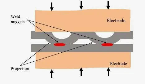
As per the definition, different projections are formed in this welding technique. Here, the metal pieces that are to be joined are kept in between the two electrodes. A larger pressure force is applied to the electrodes. As current is passed through the system, the heat formation takes place due to the internal resistance of the metal work pieces. One point that you must note down here, is that the heat generation takes place due to the internal resistance of the metal workpieces rather than an electric arc. Those projections concentrate the heat. As the pressure applied to the electrodes increases, this projection collapses and the formation of the fused weld nugget takes place. Thus, a quality weld is formed.
The exact working of the projection welding can be understood by referring the below image.
You can see in the above image that the projection means the embossed joints are formed on one of the base metals and then, these base metals are kept in between the two electrodes and force is applied perpendicular to the electrodes.
But as the applied force increases those sharp projections collapses and the formation of the weld takes place at the weld surface. The above image illustrates the formation of the weld nuggets as well as the collapsing of the sharp projections.
Characteristics of Projection Welding-
Following are characteristic of the projection welding that you must know:
A lot of manufacturers prefer the projection welding instead of other welding techniques. So, do you know the exact reason for it? Well, its answer is quite simple. In figure (b), you can see this welding technique is producing the multiple joints at the same time. So, if you have a very less time and you want the formation of the multiple welds at the same time then, projection welding is a must for you. Therefore, a lot of manufacturers use this welding process instead of others.
Another important characteristic of the projection welding is that here you get the more electrode life than the spot-welding process. So, it saves your cost of the electrodes and there is no need to change the electrodes in short intervals of time. Some of you might think, why the electrode life is longer in the projection welding than the spot welding? In the projection welding, a weld is formed as a result of the heat and the applied force. But in the case of the spot welding, a weld is formed mostly as a result of the heat generation. So, in the projection welding, electrodes are not affected by the current you are supplying. And mostly due to the force applied the required weld formation takes place. It required very less amount of current. And hence, the life of the electrode in the projection welding is much greater than the spot welding.
Sometimes, plating material is present on the metal surface and this plating may result in the formation of the cracks while welding. Projection welding removes the plating material efficiently and gives a high-quality weld. Those who want to remove the irritating plating material then, go for this welding technique.
Advantages of Projection Welding-
- Now, it is the time to know about the advantages. So, let’s discuss some of the most important benefits of this welding technique:
- As the above stated, this welding requires a very small supply of current and thus, it saves the electricity usage. So, less electricity requirement and a longer electrode life are the two most prominent benefits of this welding process.
- While doing spot welding there is a limitation on the thickness of the metal that has to be welded. But in this welding, almost metals of all thickness are welded.
- It can be used effectively for welding of the joints which are on the complicate locations.
- The heat balance is an important part of any welding process and this welding gives a good heat balance while welding.
Disadvantages of Projection Welding-
- This welding process is not applicable for some types of the coppers and brasses.
- Projection formation is a quite complicated process and it takes time to form the projections. It is very difficult to form the spherical projection and a skilled person is required to form such projections. While making those projections, a height of the projection has to be maintained properly.
- This process is not applicable to all types of work pieces. The composition of the metal work pieces has to be considered while this process and it has some limitations.
Application of Projection welding-
- As Projection welding is mostly used for the mass production. It has many applications such as:
- Automobile industry uses projection welding to a very large extent.
- This welding process is also used for the fan covers and hollow metal doors.
- It is also used for producing the compressor parts and for the semi-conductors.
- Have you heard about the diamond segment welding? In the diamond segment welding, projection welding finds its applications.
RESISTANCE SEAM WELDING-
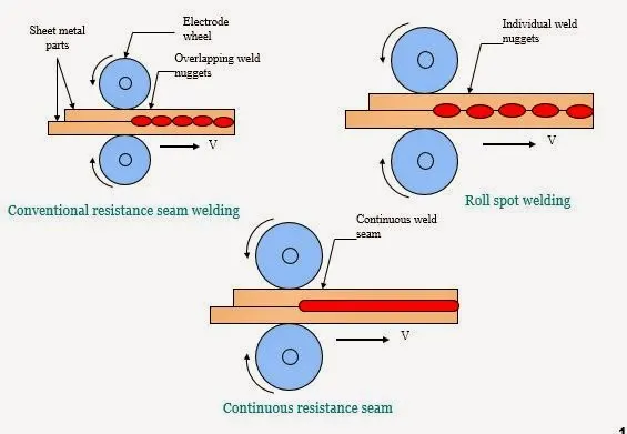
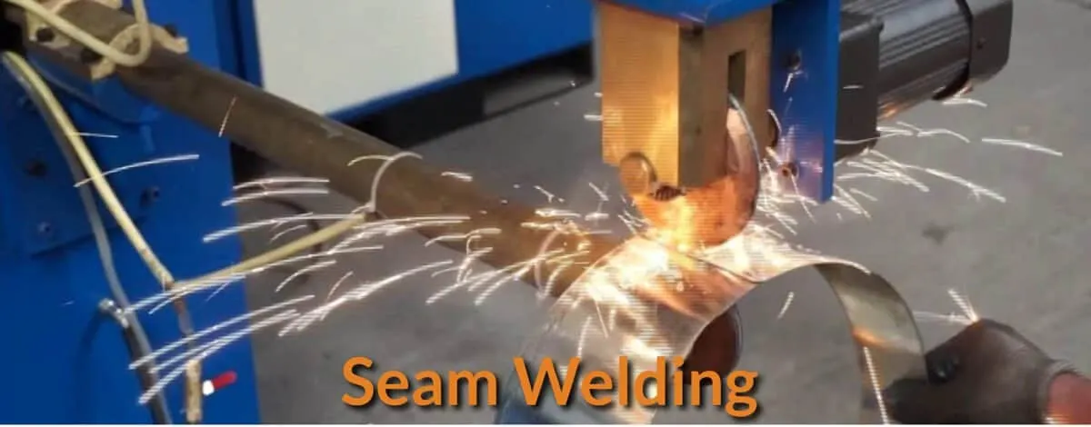
Seam welding is a resistance welding process in which overlapping sheets are joined by local fusion progressively, along a joint, by two rotating the circular electrodes. Fusion takes place because of heat, which is generated, from the resistance to electric current flow through the work parts which are held together under pressure by electrodes.
Principle Operation of Resistance Seam Welding-
The work-pieces to be seam welded are cleaned, overlapped suitably and placed between the two circular electrodes which hold the work-pieces together by the pressure on electrode force.
Switch on the coolant supply (in some machines, the electrodes are cooled by external spray of water; in others, the electrodes are cooled by refrigerant fluid that flow inside the working electrodes).
Switch on the current supply. As the first current impulse is applied, the power driven circular electrodes are set in rotation and the work-pieces steadily move forward.
If the current is put off and on quickly, a continuous fusion zone made up of overlapping nuggets is obtained. It is known as stitch welding.
If individual spot welds are obtained by constant and regularly timed interruption of the welding current, the process is known as roll (spot) welding.
Advantages of Seam Welding-
- It can produce gas tight or liquid tight joints.
- Overlap can be less than spot or projections welds.
- Several parallel seams may be produced.
Disadvantages of Seam Welding-
- Cost of equipment is high as compared to spot welding set .
- Welding can be done only along a straight or uniformly curved line.
- It is difficult to weld thickness greater than 3 mm.
Applications of Seam Welding-
It is used for welding of stainless steels, steels alloys, nickel and its alloys, magnesium alloys etc.
- RESISTANCE BUTT WELDING-
Resistance Butt Welding is a Resistance Welding (RW) process, in which ends of wires or rods are held under a pressure and heated by an electric current passing through the contact area and producing a weld.
The process is similar to Flash Welding, however in Butt Welding pressure and electric current are applied simultaneously in contrast to Flash Welding where electric current is followed by forging pressure application.
Butt welding is used for welding small parts. The process is highly productive and clean. In contrast to Flash Welding, Butt Welding provides joining with no loss of the welded materials.
Application of Resistance Butt Welding-
- Wire and rod joints up to about 16mm diameter, including chain, and narrow strip joints such as automobile road wheel rims.
- Butt welding used in automobile construction of the body, axles, wheels, frame etc.
APPLICATIONS OF ELECTRIC RESISTANCE WELDING IN AUTOMOTIVE SECTOR-
The conventional steel body of a car, on an average, contains 4500 spot weld joints. Resistance spot welding is the principle joining method used in automotive industries and has been for many years.
Welding is invariably used in the automotive industries for joining variety of structural components and engine parts. The constant demand for new improved material requirement for automotive applications necessitates the development of innovative joining techniques.
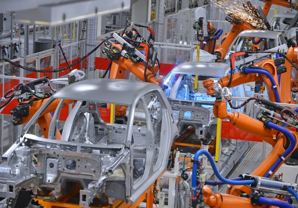
Resistance spot welding is automated and used in the form of robotic spot welding in automotive industries to weld the sheet metals to form car ody.
Industrial robots spot welding the car body in production line is shown in the picture given below.
The most common application of resistance spot welding is in the automobile manufacturing industry, where it is used almost universally to weld the sheet metal to form a car.
Resistance seam welding is used in the assembly of fuel tanks to make leak proof in the automotive industry.
Automobile industry uses resistance projection welding to a very large extent.
Resistance projection welding used for mechanical fixing of automobile body structure like weld nuts etc.
Resistance butt welding is used for wire and rod joints up to about 16mm diameter, including chain, and narrow strip joints such as automobile road wheel rims.
Resistance butt welding used in automobile construction of the body, axles, wheels frame etc.
Question 4. What is fusion welding & types of fusion welding its application in automotive sectors?
Answer 4. FUSION WELDING- Fusion welding is a process of welding by melting one or both of a base material and a filler material.
Arc welding is a common example of fusion welding. Arc welding and laser welding are generally used for automatic welding using robot arms.
In complicated product assembly lines, such as for automobile parts, robot and human welding are used depending on the characteristics or conditions of the process.
Classification of Fusion Welding-
- Thermit welding.
- Arc Welding.
- Gas welding.
THERMIT WELDING-
Thermit Welding is a welding process utilizing heat generated by exothermic chemical reaction between the components of the thermit (a mixture of a metal oxide and aluminum powder). The molten metal, produced by the reaction, acts as a filler material joining the work pieces after Solidification.
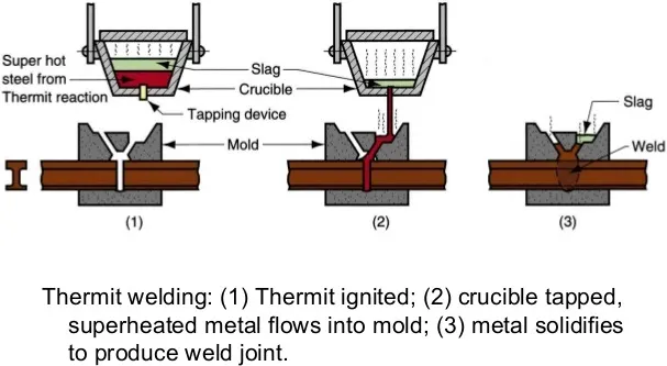
Thermit Welding is mainly used for joining steel parts, therefore common thermit is composed from iron oxide (78%) and aluminum powder (22%).
The proportion 78-22 is determined by the chemical reaction of combustion of aluminum:
8Al + Fe3O4 = 9Fe + 4Al2O3
The combustion reaction products (iron and aluminum oxide) heat up to 4500°F (2500°C). Liquid iron fills the sand (or ceramic) mold built around the welded parts, the slag (aluminum oxide), floating up , is then removed from the weld surface.
Thermit Welding is used for repair of steel casings and forgings,for joining railroad rails, steel wires and steel pipes, for joining large cast and forged parts.
Disadvantages
- Only ferrous (steel, chromium, nickel) parts may be welded;
- Slow welding rate
- High temperature process may cause distortions and changes in Grain structure in the weld region.
- Weld may contain gas (Hydrogen) and slag contaminations.
Application of Thermite welding-
- It is mostly used to weld railroad at the site.
- It was used to weld thick plate before introduce electro slag welding.
- They are used to repair heavy castings.
- It is used to weld cable connectors of copper.
- It is used to make structure joints in large ships etc.
- It is used to joint pipe, thick plate etc. where power supply is not available.
- Automobile parts are welded by this process.
ARC WELDING-
Arc welding is a type of fusion welding and is widely used in various industrial fields.
There are many varieties of arc welding that are selected depending on the material characteristics, mechanism of the equipment, and gas to be used. Gas shielded arc welding that uses a shielding gas to protect the weld from atmosphere, such as TIG welding, MIG welding, and MAG welding, has been used extensively due to ease of automation.
Arc welding, including gas shielded arc welding, is broadly divided into two types: consumable (fusible) electrode type and non-consumable (non-fusible) electrode type depending on whether the welding rod/wire melts in the process or not.
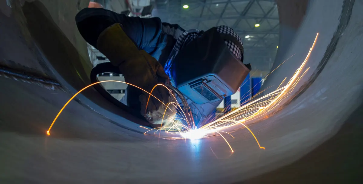
Classification of Arc Welding
Types of Arc Welding-
- Shielded Metal Arc welding.
- MIG Welding.
- TIG Welding.
- Plasma Arc Welding.
- Submerged Arc Welding.
- Electro slag Welding.
- Atomic Hydrogen Welding.
- Carbon Arc welding.
Shielded metal Arc Welding-
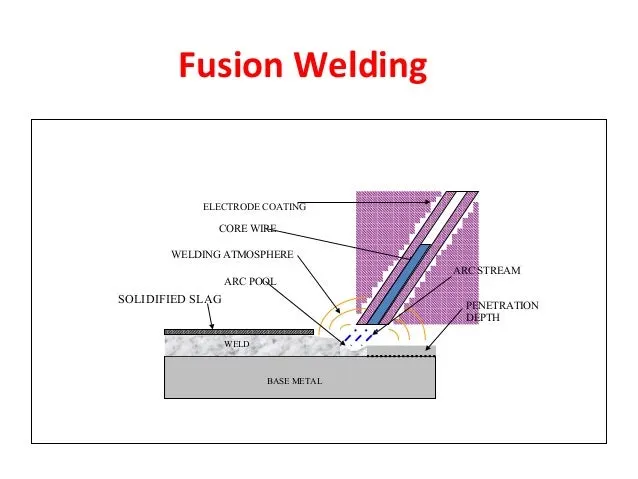
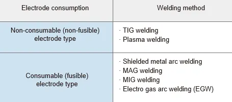
Shielded metal arc welding (Stick welding, Manual metal arc welding) uses a metallic consumable electrode of a proper composition for generating arc between itself and the parent work piece. The molten electrode metal fills the weld gap and joins the work pieces.
This is the most popular welding process capable to produce a great variety of welds.
The electrodes are coated with a shielding flux of a suitable composition. The flux melts together with the electrode metallic core, forming a gas and a slag, shielding the arc and the weld pool. The flux cleans the metal surface, supplies some alloying elements to the weld, protects the molten metal from oxidation and stabilizes the arc. The slag is removed after Solidification.
Working operation of shielded Metal Arc Welding-
In Shielded Metal Arc Welding (SMAW), for joining the metal an electric arc is formed in between the metal and electrode with the help of an electric current. This electric current may be in the form of alternating or direct current and is supplied by the welding power supply. The zone or small pool of molten metal is formed after the process of welding of work piece. This weld cools after sometimes to form a strong joint. After sometime the flux coating of electrode gives off vapours which serve as shielding gas and slag layer. This shielding gas and slag layer prevents the weld area from contamination due to atmospheric gases such as nitrogen, oxygen. For striking an electric arc, first of all, an electrode is brought in contact with the work piece. You have to just touch this electrode to the work piece and pulled back it smoothly. This will initiate the required arc and causes a transfer of small drops of electrode to the welding area or surface of work piece. This could be a difficult task for beginners. The tip of an electrode must be at some lower angles to work piece. If this angle is perpendicular then the tip of electrode will stick to the work piece which will make welding difficult process. Molten slag provides the filler metal. During the welding process welder must be aware to change the electrode periodically and insert a new electrode carefully. The speed of the Shielded Metal Arc Welding depends upon the welder’s skills, electrode type and most important welding position.
Advantages of Shielded Metal Arc Welding-
- Simple, portable and inexpensive equipment;
- Wide variety of metals, welding positions and electrodes are applicable;
- Suitable for outdoor applications.
Disadvantages of Shielded Metal Arc Welding-
- The process is discontinuous due to limited length of the electrodes;
- Weld may contain slag inclusions;
- Fumes make difficult the process control.
Applications-
1) It is dominantly used in industrial fabrication industries.
2) Stick welding is used in repair companies.
3) It is used in the construction of steel structures and in the welding process of cast iron and ductile iron.
- MIG Welding-
It is an arc welding technique in which a consumable electrode is used to weld two or more work piece.
MIG welding makes use of the following components: consumable electrode, Inert gas supply, Welding head, AC or DC supply.
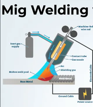
Working operation of MIG Welding-
The MIG welding process is based on the principle that a consumable metal electrode is used to produce an arc in between the metal electrode and the workpiece. The arc so produced creates a large amount of heat and this heat is used to join the two metal pieces together. The whole process takes place under a shielding gas (argon or helium) to prevent the weld from atmospheric contamination.
Power Supply-
The MIG welding process or GMAW most commonly uses constant voltage, direct current power source for the welding. It can also use constant current systems and alternating current.
Shielding Gas-
The shielding gases are of two types- inert or semi inert. The shielding gases that are used in MIG welding are
Argon and helium are inert and most cost effective shielding gas used in the MIG welding. Pure argon and helium is used to weld non-ferrous materials.
The semi- inert gases are the mixtures of carbon dioxide, nitrogen, hydrogen, and oxygen in the argon.
Working of MIG Welding-
In MIG welding process, the electrode wire from the wire feed unit and shielding gas supply is attached with the welding gun. The positive terminal of the DC power source is connected to the welding gun and the negative terminal is connected to a clamp.
The clamp is connected to the work piece to be joined. The welding gun is brought near the work piece and as the trigger is pressed, the arc is produced at the tip of the welding gun. The arc produced melts the electrode wire and it gets deposited in between the two metal pieces to be joined and form a slag free weld.
A shielding gas also starts to spread as the arc is produced. It protects the weld from reacting with atmospheric air and prevents weld from contamination.
The weld formed in Gas Metal Arc Welding is free from slag. It is a clean and efficient process.
This is the working of the GMAW or MIG welding process.
Advantages of MIG Welding-
- It is faster welding process.
- It has greater deposition rates.
- It provides better weld pool visibility.
- After the welding process is over, it requires less cleaning.
- A semi-skilled operator can operate MIG welding easily.
- It can be learned easily without much hard work.
- Absence of filler metal. The consumable metal electrode itself works as filler metal.
- The MIG welding process can be automated easily.
- It is a clean and efficient welding process.( no slag to chip off the weld)
Disadvantages of MIG Welding-
- Its initial setup cost is high.
- High maintenance costs because of more electronic equipment.
- It creates a radiation effect which is more severe.
- It is not suitable for outdoor welding.
- Thick metals cannot be welded by GMAW or MIG welding process.
- It is not capable to weld in all positions.
Application of MIG Welding-
- The GMAW or MIG welding process are mostly used in automotive industries and pipe industries, building bridges and in the repair work.
- We have studied about what is MIG Welding Process or Gas Metal Arc Welding (GMAW). Here we have discussed about working principle, equipment, working, advantages and disadvantages etc. If you have any query then comment us.
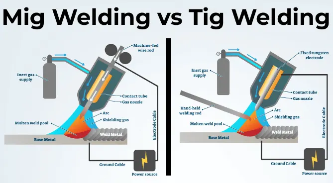
TIG WELDING-
It is an arc welding method that uses a non-consumable tungsten electrode to weld two or more work pieces.
It is very much similar to MIG welding.
The following components are required to perform TIG welding. They are : power supply, Non-consumable tungsten electrodes, Inert gas supply, Filler rod(depends on nature of work piece), Welding head.
Working Principle of TIG Welding-
TIG welding works on same principle of arc welding. In a TIG welding process, a high intense arc is produced between tungsten electrode and work piece. In this welding mostly work piece is connected to the positive terminal and electrode is connected to negative terminal. This arc produces heat energy which is further used to join metal plate by fusion welding. A shielding gas is also used which protect the weld surface from oxidization.
First, a low voltage high current supply supplied by the power source to the welding electrode or tungsten electrode. Mostly, the
electrode is connected to the negative terminal of power source and work piece to positive terminal.
This current supplied form a spark between tungsten electrode and work piece. Tungsten is a non –consumable electrode, which give a highly intense arc. This arc produced heat which melts the base metals to form welding joint.
The shielded gases like argon, helium is supplied through pressure valve and regulating valve to the welding torch. These gases form a shield which does not allow any oxygen and other reactive gases into the weld zone. These gases also create plasma which increases heat capacity of electric arc thus increases welding ability.
For welding thin material no filler metal is required but for making thick joint some filler material used in form of rods which fed manually by the welder into welding zone.
Application of TIG Welding:
- Mostly used to weld aluminum and aluminum alloys.
- It is used to weld stainless steel, carbon base alloy, copper base alloy, nickel base alloy etc.
- It is used to welding dissimilar metals.
- It is mostly used in aerospace industries.
Advantages of TIG Welding:
- TIG provides stronger joint compare to shield arc welding.
- The joint is more corrosion resistant and ductile.
- Wide verity of joint design can form.
- It doesn’t required flux.
- It can be easily automated.
- This welding is well suited for thin sheets.
- It provides good surface finish because negligible metal splatter or weld sparks that damage the surface.
- Flawless joint can be created due to non-consumable electrode.
- More control on welding parameter compare to other welding.
- Both AC and DC current can be used as power supply.
Disadvantages of TIG Welding:
- Metal thickness to be weld is limited about 5 mm.
- It required high skill labor.
- Initial or setup cost is high compare to arc welding.
- It is a slow welding process.
PLASMA ARC WELDING-
The hot ionized gases are known as plasma. When a sufficient amount of energy provided to any inert gas, some of its electrons breaks free from its nucleus but travel with it. After the electrons leave, the atoms are converted into hot ionized state. It is most common state of matter which is known as fourth state of matter. These ionized atoms have high heat contain which is further used to join two plates. This is basic principle of plasma arc welding. This welding is extended form of TIG welding in which, a non-consumable tungsten electrode is used to produce arc. This arc heats up the inert gases which are provided from inner orifice around tungsten electrode. The heating temperature is about 30000 degrees centigrade at which the gas converts into ionized form. This hot ionized gas further used to create a welding joint by fusion.
Working-
This welding works on same as TIG instead, plasma is used to heat up the parent material. Its working can be summarized as follow.
First the work pieces are properly cleaned. The power source supply power which produces arc between tungsten electrode and nozzle, or tungsten electrode and workpiece.
The tungsten electrode gives a high intense arc which is used to ionization of gas particles and converts orifice gases into plasma. This hot ionized gas is supplied to the welding plates from a small orifice.
The shielding gases like argon etc. are supplied through pressure valve and regulating valve to the outer nozzle of welding torch. These gases create a shield around the welding area which protect it from atmospheric gases like oxygen, nitrogen etc.
The plasma strikes the welding plates and fuses it into one piece. Next the welding torch is moved in the direction of welding.
If the welding required filler material, it is fed by the welder manually.
This is whole working process of plasma arc welding.
Application:
- This welding is used in marine and aerospace industries.
- It is used to weld pipes and tubes of stainless steel or titanium.
- It is mostly used in electronic industries.
- It is used to repair tools, die and mold.
- It is used to welding or coating on turbine blade.
Advantages:
- High welding speed.
- High energy available for welding. It can be easily used to weld hard and thick work pieces.
- The distance between tool and work piece does not effects the arc formation.
- Low power consumption for same size weld.
- More stable arc produced by PAW method.
- High intense arc or high penetration rate.
- It can work at low amperage.
Disadvantages:
- Higher equipment cost.
- Noisy operation.
- More radiation.
- High skill labor required.
- High maintenance cost.
SUBMERGED ARC WELDING-
Submerged arc welding (SAW) is a welding process where the tubular electrode is fed continuously to join two metals by generating heat between electrode and metal.
The area of the arc and molten zone gets its protection from the atmospheric contamination by submerging under a blanket of granular flux. The flux layer covers the area completely preventing spatter, sparks, fumes, and UV radiation.
Process and Principle of Operation-
In the submerged arc welding process the flux-covered electrode is replaced by the granular flux and a bare electrode. An arc between the electrode and job is the source of the heat and remains buried under a blanket of flux. This flux keeps the atmospheric contamination away. The process may be automatic or semi-automatic.
Once the trigger is pulled the flux starts depositing at the joint to be welded. The cold flux is a non-conductor of electricity, so arc may be struck by touching the electrode with the base metal. The arc may be struck by placing the steel wool between electrode and job metal and use high-frequency current.
It strikes the arc under the cover of the flux. once flux is heated and melt to become highly conductive. The upper layer remains unchanged and acts as protection while the lower layer remains electrically conductive to maintain the arc. The upper layer remains unchanged and granular, which can be reused.
The electrode moves a predetermined speed continuously to feed at the joint to be welded. The melted metal from the electrode is transferred to the work piece and gets deposited. The flux close to the arc melts and intermingles with molten metals. This flux forms a slag lighter than the deposited metal as a protective layer. The weld remains submerged under a layer of flux and slag, so is the name submerged arc welding.
The electrode feeding is continuous by a coil. The arc is preserved automatically by flux. The travel may be managed by manual or by machine.
Advantages of Submerged Arc Welding-
- Very high welding rate;
- The process is suitable for automation;
- High quality weld structure.
Disadvantages of Submerged Arc Welding-
- Weld may contain slag inclusions;
- Limited applications of the process - mostly for welding horizontally located plates.
ELECTRO SLAG WELDING-
Electro slag welding is an uphill welding process. Uphill welding process is a process in which weld joints are made in vertical direction and the plates to be weld held vertically.
This welding is done both in single pass and multi pass.
Before discussing its working we should learn about the principle of electro slag welding machine.

Principle-
It works on common principle of heat generation due to arc and electric resistance. At the starting, arc is produce between welding electrode and base metal which tends to melt filler metal. This filler metal will fill the cavity at some extent. Now the current passes through this extended surface and heat generate due to electric resistance. This heat further tends to melt filler metal which is continuously fed from the roller. Filler wire is fed through the roller continuously. This wire fed through a tube witch direct its flow. This filler wire melts and fills the weld and made a strong joint.
Working of Electro slag Welding:
As we know, electro slag welding is an uphill welding process so the plates to be weld held vertically at some distance. The weld metal or filler metal deposit between the cavities formed between the plates by melting electrodes using heat develop by flow of current. This filler metal forms metal pool which solidified into the weld cavity so a strong joint is created between the plates. Electro slag welding works as follow.
- First current is flow between welding electrode and base plate. This establishes an arc between electrode and base plate which heat the flux or filler wire. This heat leads to melt the filler metal and deposits into the weld cavity.
- Now the cooled copper shoe comes into action and start solidified this filler metal into weld cavity. This will made to avoid flowing out the weld metal.
- As the filler metal solidified into weld cavity, the current flow through it. It will generate heat due to electric resistance. This heat is further use to continuous melting down the filler metal into weld Cavity.
- The filler metal continuously provide through roller arrangement as shown in figure.
- During welding both the copper shoe and feed mechanism moving upward unlit the whole cavity is formed.
- This will create a strong joint in single pass. The single or multi-pass weld is used according to plate thickness.
Application-
- It is used in heavy industries where plate thickness up to 80mm to be joint.
- This process is used to joint large casting and forging to produce very large and composite structure.
- Welding of thick walled large diameter pipes, pressure vessels, storage tanks and ships etc.
Advantages-
- Cooling rate is very low so there is no problem of cold cracking.
- There is no problem of slag inclusion or porosity in electroslag welding.
- The process is semi-automatic and faster.
- Heavier section can be welded in single pass.
- High productivity can be achieved.
- Low cost for joint preparation.
Disadvantages-
- Too high heat input to base.
- High temperature of welding needs cooling arrangement.
- Slow rate of cooling give columnar grain in weld.
ATOMIC HYDROGEN WELDING-
Atomic Hydrogen Welding (AHW) is a combination of electric arc and gas welding technique.
It is a thermo-chemical arc welding process in which the work pieces are joined by heat obtained on passing a stream of hydrogen through an electric are struck between two tungsten electrodes.
The electric arc efficiently breaks up the hydrogen molecules which recombine with tremendous release of heat with the temperature from 3400 to 4000°C.
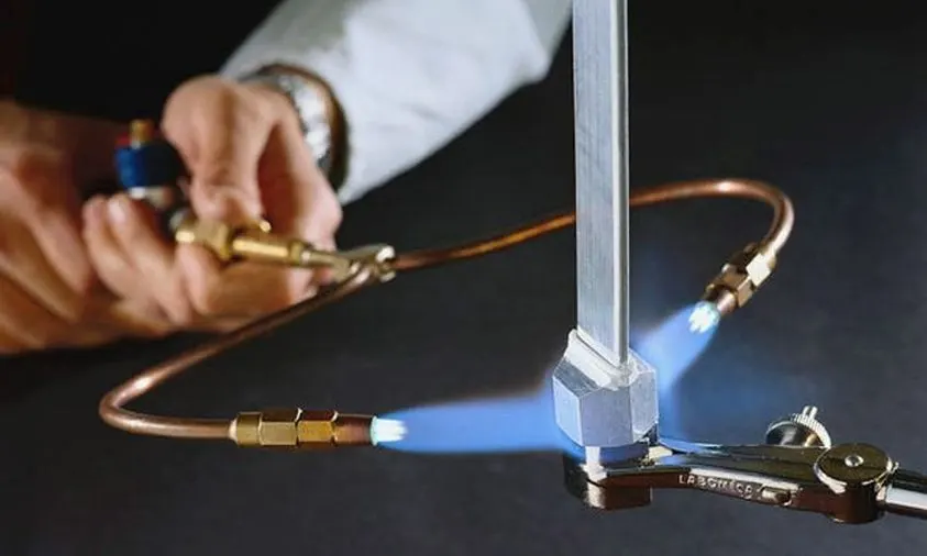
The process has the following special features.
- High heat concentration is obtained.
- Hydrogen acts as a shield against oxidation.
- Filler metal of base composition could be used.
- Most of its applications can be met by MIG process. Therefore, it.is not commonly used.
Working of Atomic Hydrogen Welding-
The equipment consists of a welding torch with two tungsten electrodes inclined and adjusted to maintain a stable arc as shown in Figure 4.4. Annular nozzles around the tungsten electrodes carry the hydrogen gas supplied from gas cylinders. AC power source is suitable as compared to DC because equal amount of heat will be available at both electrodes. A transformer wjih an open circuit voltage c.f 300 Pis required to strike and maintain the arc.
The work pieces are cleaned to remove dirt, oxides and other impurities to obtain a sound weld. Hydrogen gas supply and welding current are switched ON. An arc is struck by bringing two tungsten electrodes in contact with each other and instantaneously separated by a small distance of 1.5 mm. Therefore, the arc still remains between two electrodes.
As the jet of hydrogen gas is passed through the electric arc, it disassociates into atomic hydrogen by absorbing large amounts of heat supplied by the electric arc.
H2aBH + H = 422 kJ (Endothermic Reaction)
Advantages of Atomic Hydrogen Welding-
- Welding process is faster.
- During the process, intense flame is obtained which can be concentrated at the joint. Hence, less distortion occurs.
- There is no requirement of separate flux and shielding gas or flux. The hydrogen envelop itself prevents oxidation of the metal and tungsten electrode. It also reduces the risk of nitrogen pick-up.
- Work piece do not form a part of the electric circuit. Hence, problems such as striking the arc and maintaining the arc column are eliminated.
- Welding of thin materials is also possible which may not be successfully carried out by metallic arc welding.
- The work piece does not form a part of the electrical circuit. The arc remains between two tungsten electrodes, and it can be moved to other places easily without getting extinguished.
Limitations of Atomic Hydrogen Welding-
- The post of welding is high when compared to the other process.
- Welding process is limited to flat positions only.
- The process cannot be used for depositing large quantities of metals.
- Welding speed is less when compared to metallic arc or MIG welding.
Applications of Atomic Hydrogen Welding-
- These welding processes are used in welding of tool steels which contains tungsten, nickel and molybdenum.
2.They are used in joining parts, hard surfacing and repairing of dies and tools.
- Atomic hydrogen welding is used where rapid welding is necessary in stainless steels, non-ferrous metals and other special alloys.
CARBON ARC WELDING-
Carbon Arc Welding (CAW) is a welding process, in which heat is generated by an electric arc struck between carbon electrode and the work piece. The arc heats and melts the work pieces edges, forming a joint.
Carbon arc welding is the oldest welding process.
If required, filler rod may be used in Carbon Arc Welding. End of the rod is held in the arc zone. The molten rod material is supplied to the weld pool.
Shields (neutral gas, flux) may be used for weld pool protection depending on type of welded metal.
Advantages of Carbon Arc Welding:
- Low cost of equipment and welding operation;
- High level of operator skill is not required;
- The process is easily automated;
- Low distortion of work piece.
Disadvantages of Carbon Arc Welding:
- Unstable quality of the weld (porosity);
- Carbon of electrode contaminates weld material with carbides.
GAS WELDING-
- Gas Welding is a welding process utilizing heat of the flame from a welding torch.
- The flame is produced at the tip of the welding torch.
- No pressure is applied during welding except pressure gas welding.
- The hot flame fuses the edges of the welded parts, which are joined together forming a weld after Solidification.
- Filler rod is used when an additional supply of metal to weld is required. Shielding flux may be used if protection of weld pool is necessary.
- Most of commercial metals may be welded by Gas Welding excluding reactive metals (titanium, zirconium) and refractory metals (tungsten, molybdenum)
The most popular methods of Gas Welding are:
- Oxyacetylene Welding
- Oxyhydrogen Welding
Oxyacetylene Welding -
Oxy-acetylene welding uses a mixture of acetylene gas and oxygen gas to feed the welding torch. Oxy-acetylene welding is the most commonly used gas welding technique.
This gas mixture also provides the highest flame temperature of available fuel gases, however acetylene is generally the most expensive of all fuel gases. Acetylene is an unstable gas and requires specific handling and storage procedures.
There are two types of Oxy – acetylene systems employed dependind upon the manner in which acetylene is supplied for welding. They are high pressure system & low pressure system.
In High pressure system, both oxygen & acetylene are supplied from high pressure cylinders.
In Low pressure system, the acetylene produced at the place of welding by interaction of calcium carbide & water in acetylene generator.
Oxyacetylene flame has a temperature of about 6000°F (3300°C). Combustion of acetylene proceeds in two stages:
- Inner core of the flame. C2H2 + O2 = 2CO + H2
- Outer envelope of the flame: CO + H2 + O2 = CO2 + H2O
Acetylene is safely stored at a pressure not exceeding 300 psi (2000 kPa) in special steel cylinders containing acetone. Outside of cylinder acetylene is used at absolute pressure not exceeding 30 psi (206 KPa). Higher pressure may cause explosion.
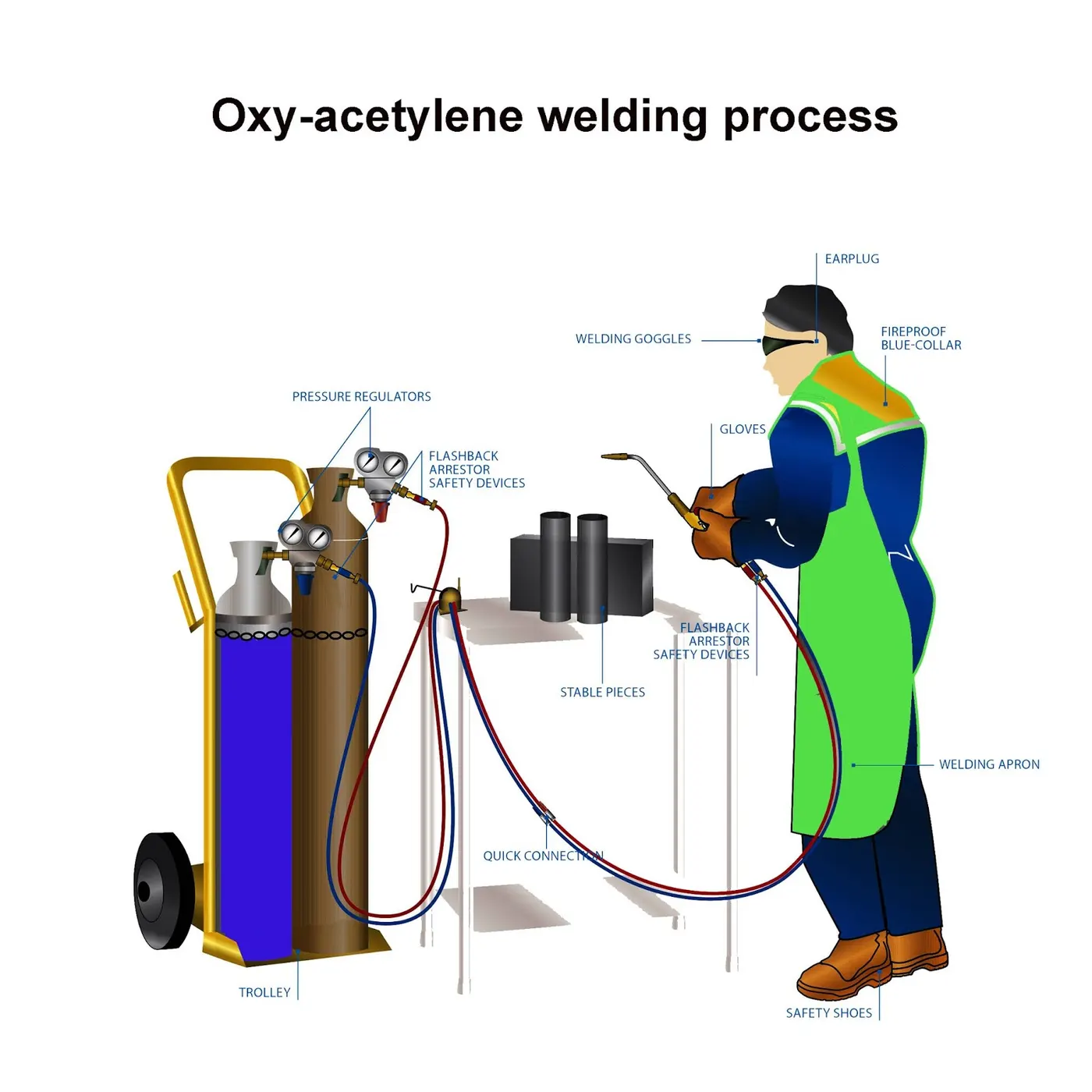
Oxyhydrogen Welding -
Oxyhydrogen Welding is a Gas Welding process using a combustion mixture of Hydrogen (H2) and oxygen (O2) for producing gas welding flame.
Oxyacetylene flame has a temperature of about 4500°F (2500°C).
Combustion reaction is as follows:
2H2 + O2 = 2H2O
Oxyhydrogen Welding is used for joining metals with low melting points, like aluminum, magnesium, etc.
Pressure Gas Welding -
Pressure Gas Welding is a Gas Welding, in which the welded parts are pressed to each other when heated by a gas flame.
The process is similar to Resistance Butt Welding.
Pressure Gas Welding does not require filler material.
Pressure gas welding is used for joining pipes, rods, railroad rails.
Application of gas Welding-
- It is used to join thin metal plates.
- It can be used to join both ferrous and non-ferrous metals.
- Gas welding mostly used in fabrication of sheet metal.
- It is widely used in automobile and aircraft industries.
Advantages of Gas Welding-
- It is easy to operate and dose not required high skill operator.
- Equipment cost is low compare to other welding processes like MIG, TIG etc.
- It can be used at site.
- Equipment’s are more portable than other type of welding.
- It can also be used as gas cutting.
Disadvantages of Gas Welding-
- It provides low surface finish. This process needs a finishing operation after welding.
- Higher safety issue due to naked flame of high temperature.
- It is Suitable only for soft and thin sheets.
- Slow metal joining rate.
- No shielding area which causes more welding defects.
Fusion Welding Applications In Automotive Sectors-
- Fusion welding is used in the manufacturing of automobiles and construction equipment.
- Gas welding – used to weld parts of the frame and the chassis.
- Manual metal arc welding truck frames and bodies, heavy machineries, two – wheelers frames, earth moving equipments etc.
- Used to join various automobile parts.
Question 5. What is the 3-2-1 Principle?
Answer 5. FIXTURE- A fixture is a device which holds the work piece to be processed (welded) by using 3-2-1 principle.
FIXTURE DESIGN-
- Fixture must be correctly located a work piece in a given orientation with respect to another component.
- Locating & clamping are the critical function of any work holding fixtures.
- A work piece in a space can move in an infinite no. of directions for analysis, this motion can be broken down into 12 directional movement or degrees of freedom.
- All the 12 degrees of freedom must be restricted to ensure proper referencing of the work piece.
3-2-1 PRINCIPLE- The best & most cost effective method of part location is referred to as the 3-2-1 method.
(3) Minimum- Three locator blocks to establish part plane. Three locator or supports are placed under the work piece. Three locators are usually positioned at the primary locating surface. This restricts two axial movement downward & upward and four radial movements. Together, the three locators restricts six degree of freedom.
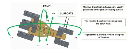
(2) Round locating pin- A round hold that defines location in four directions (4-Way) perpendicular to the plane previously established. This restricts four axial movement.
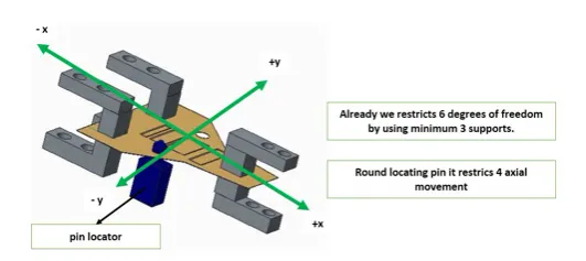
(1) Round locating pin- In a slot that defines two of the direction of other pin (2-way). This restricts two radial movements.
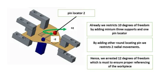
Question 6. - Define body co-ordinate system?
Answer 6. Body Co-ordinate System In BIW- The body co-ordinate system has been widely used in the automotive industries for drawing body parts, products & process design.
A co-ordinate system is reference system is reference system consisting of a set of points, lines & surface used to define the position of points space in either two or three dimension.
In general body co-ordinate system(BCS) is also called as car line and body line.
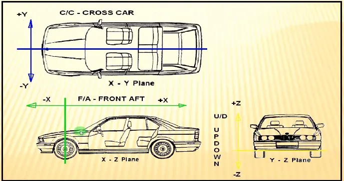
X = Longitudinal direction (Fore & After- F/A) or (Front ‘O’ Line - FOL).
Y = Transverse direction (Cross Car - C/C) or (Centre ‘O’ line).
Z = Vertical direction (Up & Down -U/d) or (Bottom ‘O’ Line).
The origin of the body co-ordinate system (OX) is defined at the front centre of the vehicle. It indicates the length of the car.
The co-ordinate system (OZ) is below its underbody indicates the height of the car.
The co-ordinate system (OY) its starting point is the centre of car body indicates the width of car.
The origin will be differ from car makers to car makers.
Question 7. - Elaborate Body plane system & its essentials?
Answer 7. Body planes are the reference plane in an automotive car. These planes are used to define the GD&T of all car parts in automotive domain.
Body planes are three mutually perpendicular imaginary planes. These are generally considered to be present at the driver position or sometimes at the engine location or at the front end of the car depending on the customers.
The measurement from the body planes to the parts are called Body line dimensions.
These body planes are called as,
- FOL - Front ‘O’ Line.
- COL - Centre ‘O’ Line.
- BOL - Body ‘O’ Line.
- The measurement along FOL or X axis is called as F/A or Front aft.
- The measurement along COL or Y axis is called as C/C or cross car.
- The measurement along BOL or z axis is called as U/d or up down.
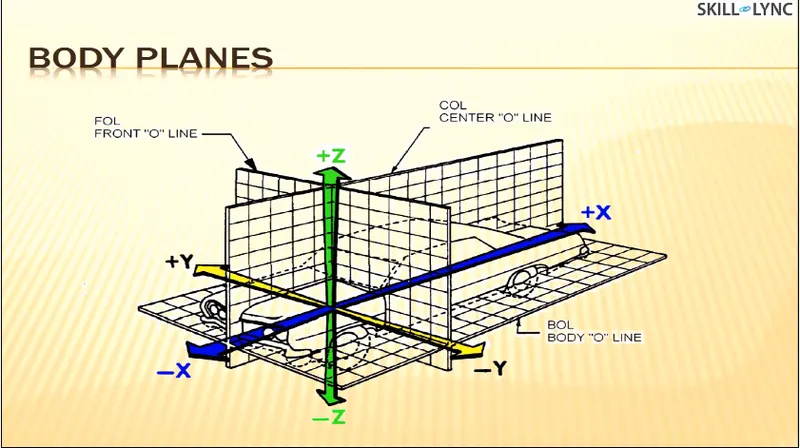
Necessity Of Body Planes-
Body lines dimensions are essential for the reason stated below,
- It defines the exact position of each product in the vehicle with respect to a fixed origin.
- It ensures the flawless designing for assembly.
- While designing lines, all the designs are carried out relative to the body lines, Viz.fixtures, turn table etc.
- It assists in easy location of different parts in a vehicle.
- It aims in creating a standardized system.
- It assists in quality checks.