Week 2:- BiW Fixture Basics Challenge
1)What is the process of project execution activity?
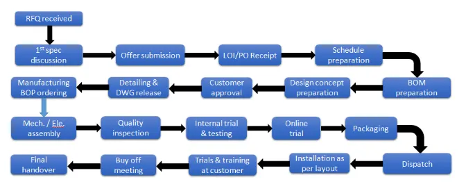
1)RFQ received - This id the first step in any project. RFQ stands for Request for Quotation. In this customer specifies his requirements, specifications etc. in form of documents or data. Also customer specifies its Technical offer, commercial offer, how the project will be executed & timeline to complete the project in it.
2) 1st spec discussion & offer submission - In this the documents related technical offer, commercial offer, project execution, Timeline required to complete the project are prepared. The time required to 3D design ,Analysis of design, drawing & detailing, manufacturing, Assembly & commisioning etc. is considered. Then the cost of all the operation is also considered. By considering these kind of things the offer is prepared & submitted to the customer.
3) LOI/PO Receipt - The customer will study the offer submitted. He will also take quotations from others. The customer will study all the offers, compare offers & then select oner offer which suits best. The customer will generate po means Purchase order to start the work.
4) Schedule preparation - After receiving the PO the project officially start. The timeline is fixed so there should be plan to beat the deadline & to complete the project. All the activities step by step are taken into account like po receipt, 1st meeting, design date analysis, 3D design preparation & simulation etc. the time required to finish the individual activity is calculated. By calculating all the steps the total time required is calculated. It should beat the timeline & if not then modifications is done in schedule to beat the timeline of the project. We should have some back up plan for this Because due to some reasons our tasks not complete on the fixed date or the next task is dependent on previous task.
5)BOM preparation - Bill of material is prepared for the project like the BO parts, grippers, cylinders, motors etc. which are required.
The bill of material contains >35 parameters mapped per part with hierarchy mapped as it is on the Body In White. These parameters mapped here help in understanding the weight distribution, quantity, purpose, coating types & thickness, part’s box size & joinery types etc. Basically, all parameters that either impact cost or the function of the part is mapped and later utilized for VA-VE activity, directional costing & engineering inputs.

6) Design concept preparation - The customer gives data or the specifications for the design. Based on that data design process is start which fulfills all the customer requirements.
7) Customer approval - After designing the concept the approval of the customer is required. Customer checks the design fulfills the requirements or not according to the technical offer. If yes the customer gives approval for the design or customer will also ask for some addition or the changes in the design. By doing the necessary changes final approval is taken from the customer.
8) Detailing & DWG release - After the approval from customer DWG are released which shows the detailed specifications of all the parts required. Like dimensions, Qty, Specifications etc.
9) Manufacturing BOP ordering - The BO parts like motors, cylinders, sensors, gripper etc. required for manufacturing are ordered as per the design specifications.
10) Mechanical/ Electrical assembly- Once the parts are received they goes for the prior Quality control checking. In this all the parts are checked as per the specification. After QC checking the Mechanical or electrical assemblies are prepared as per the design.
11)Quality inspection - After the assembly again the quality is checked. In this all the dimensions, positional accuracy, Coordinates are checked by using CMM machine.
The control of the system is carried out in ‘by-pass’ mode, perfectly integrated into the production line, and within the vehicle assembly process. This solution allows to maintain the availability of the assembly line, control all critical characteristics, and provide the same quality of measurements as the original three-dimensional CMM machines.
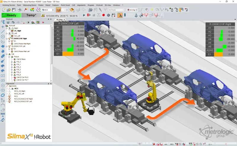
Measurement performance accuracy, along with the complete measurement applications, is driven by Metrologic Group’s Metrolog X4 i-Robot software in the automated environment which has been approved by the automotive manufacturer.
12) Internal trial & testing & online trial - After the QC check internal trials are taken to check the fixture can do the operation or not for what it is designed. The simulation is done for this purpose at early stage. In this the fixture is checked for the clamping of the part, welding ,proper loading & unloading of the part etc.
After this online trial is taken in which all the operations done in automated mode by using electrical connections. The process sequence is checked as per the defined way in design in automated mode. Customer is also involved in online trial for taking the approval.
13) Packaging & dispatch - The assemblies are packed in proper manner. Because in trasportation the fixture will be damaged hence it distorts the geometry of the fixture & also the functionality of the fixture. Hence the proper packaging is very important. Once the packaging is done the fixture is dispatched to the customer address.
14) Installation as per layout - layout is the space defined for the parts like fixture, robots etc. according to the functionality, application, process sequence etc. The layout is done at very initial level & according to that installation is done.
15) Trials & training at customer - Production trials are taken at customers end. In technical offer we have specified the quality benchmarks for the fixture, the capability of the fixture for production etc. The trials are taken to check the capability of the fixture. Once it is done then training is given to the operator, staff & engineer for the process sequence, how the fixture works, loading & unloading of the part etc.
16)Buy off meeting & Final handover - After production trial & training Customer check all the prescribed things in the offer are done or not. Sometime customer want some addition work also, so according to the requirement all the points are closed & after that project finally handover to the customer.
2)What are the types of joining processes?
Joining Processes are the processes that are used for joining metal parts. Also defined as joining of two metal parts either temporarily or permanently with or without the application of heat or pressure.
There are two types of joining processes named as -
Metallurgical joining -
Metallurgical joining includes fusion welding, pressure welding and brazing/soldering which use different energies. There are also methods of chemical joining that use adhesives.
Different types of metallurgical joining are described below
(A) Welding -
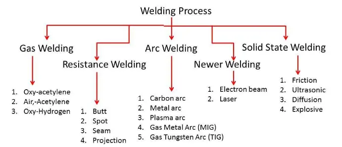
Welding is a joining process for metals wherein the work pieces to be joined as well as the welding or filler material used experience some melting. A common method for welding, known as arc welding, consists of generating an electric arc between an electrode (which contains the welding or filler material) and the work pieces to be welded together. The arc generates enough heat to melt the electrode and the areas of the work pieces were the welding is performed.
As the electrode passes over a region while the arc is present, molten metal from the electrode and molten base metal from the work pieces all get mixed together, solidifying to form a strong joint upon cooldown.The electrode contains some flux material, the purpose of which is to stabilize the arc formed by generating gases (carbon dioxide, carbon monoxide, water vapor) that shield the arc from the surrounding atmosphere.
The high temperature of the welding process alters the microstructure of the welded areas of the work pieces, i.e., these areas (known as the 'heat-affected zone' or HAZ) undergo grain coarsening at the very least. This results in a reduction of the tensile strength and toughness of the metal. Residual stresses that develop as the metal cools down also reduce the strength of the welded joints. Thus, the welding process must be optimized (by optimizing heat generation, metal compositions, and cooling rates) in order to minimize microstructural changes and residual stresses in the welded joints. Post-welding treatments are also often performed to relieve residual stresses and make the microstructure of the welds more uniform.
(B) Brazing -
• It is a joining process in which a filler metal is melted and
distributed by capillary action between the faying
(contact) surfaces of the metal parts being joined.
• Base material does not melt in brazing, only the filler
melts.
• In brazing, the filler metal has a melting temperature
(liquidus) above 450°C, but below the melting point
(solidus) of base metals to be joined.
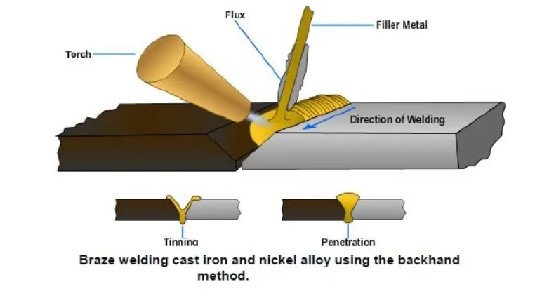
Brazing is a process for joining two work pieces together with a filler metal that is sandwiched between them, wherein only this filler metal undergoes melting, i.e., the work pieces do not experience any melting. The temperature at which brazing is done must therefore be high enough to melt the filler material, but not the work pieces. Materials used as fillers for brazing are those that melt above 450 deg C. Flux is also used during brazing for the purpose of eliminating oxide films from the surfaces of the work pieces and preventing oxidation. This would ensure a good metallurgical bond between the work pieces and the filler once the brazing process is completed .Once melted, the brazing material fills up the spaces between the surfaces being joined, and even manages to get into tight spaces by capillary action. A strong joint is obtained after the brazing material has cooled down.
Other types: Furnace brazing, Induction brazing, Resistance brazing, Dip brazing, Infrared brazing
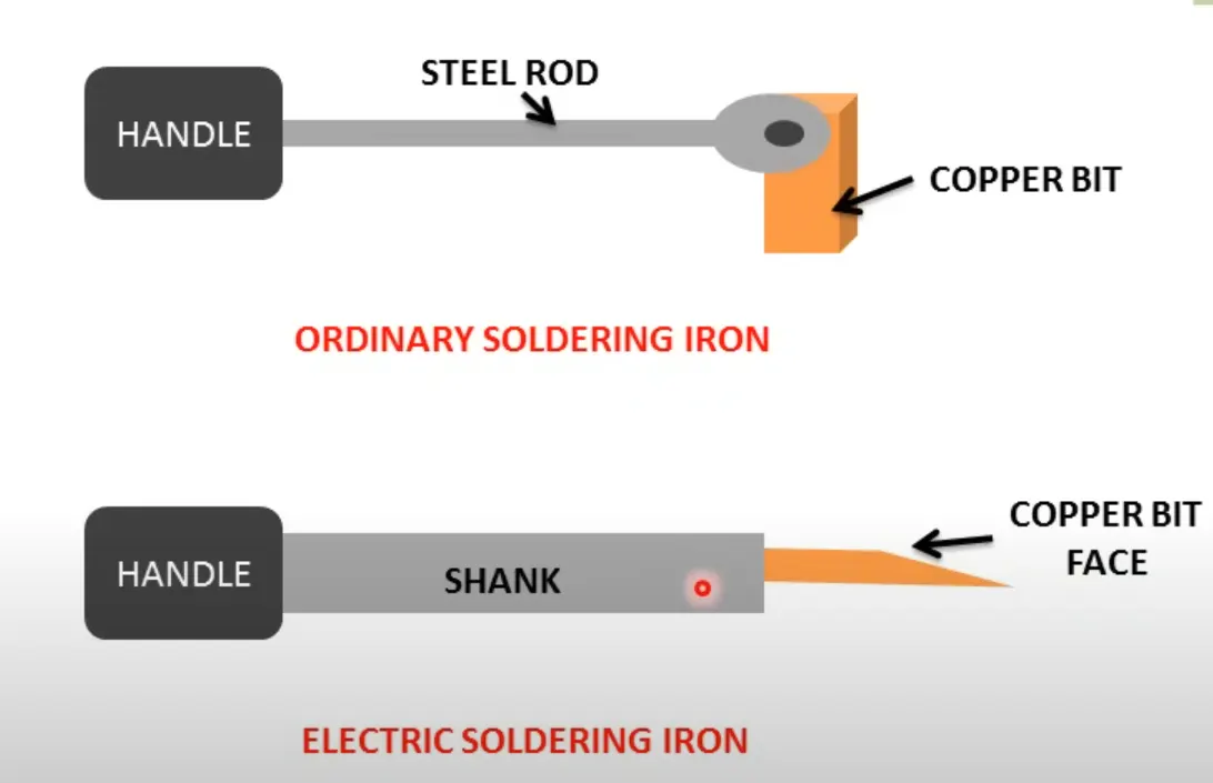
(C) Soldering -
Soldering is a joining process that's similar to brazing, except that it is performed at much lower temperatures than brazing. Thus, soldering is also a process of joining two work pieces together with a filler metal, such that only this filler metal undergoes melting, i.e., the work pieces do not experience any melting. Brazing materials are those that melt above 450 deg C, so soldering materials would be those that melt at less than 450 deg C.
Common soldering materials include tin-lead, tin-zinc, lead-silver, and cadmium-silver alloys. Like welding and brazing, soldering also employs flux materials to clean the surface to be soldered and improve metallurgical bonding. Residues from fluxes, however, must be removed after soldering to reduce the risk of the occurrence of corrosion.
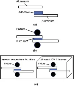
(D) Adhesive Bonding -
Adhesive Bonding is a process for joining parts using bonding chemicals or materials known as adhesives. It is employed to join polymers and polymer-matrix composites, as well as polymers to metals, metals to metals, and ceramics to metals. Adhesive-bonded joints can withstand shear, tensile, and compressive stresses, but they do not exhibit good resistance against peeling. To overcome the weakness of adhesive bonding against peeling, joints mated together by adhesives must have a good design, i.e., the adhesion area is maximized and mechanical interlocking is employed.
High adhesive bond strength is achieved if chemical bonds are formed between the adhesive and the base material, or adherent. However, compared to welding, brazing, and soldering, it is not easy to achieve primary bonding (ionic, covalent, and metallic) in adhesive bonds because of the relatively larger interfacial gaps between the adhesive and the adherent. Secondary bonds, which do not involve electron transfer or electron sharing but instead rely on coulombic forces of attraction, is therefore more likely to form in adhesive bonding.
To maximize adhesive bonding strength, surfaces to be joined by adhesives must be cleaned thoroughly. This, in essence, minimizes the interfacial gap between the adhesive and the adherent. Making the surfaces 'rough' also improves adhesive bond strength because of the mechanical interlocking that the 'roughness' provides.
(E) Diffusion Bonding -
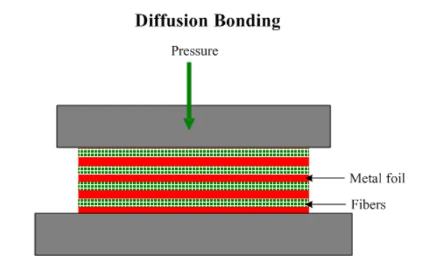
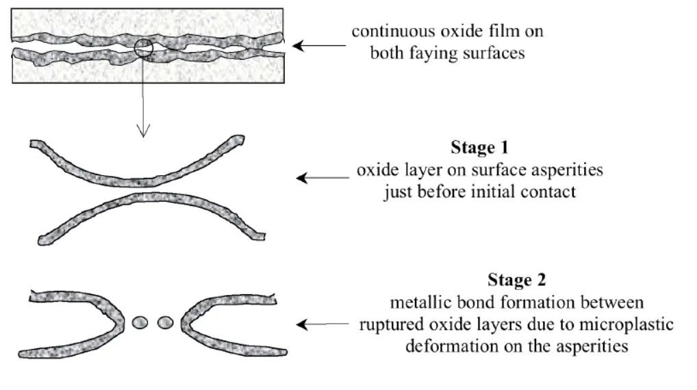
Diffusion Bonding, or diffusion welding, is a solid-state joining process wherein the joined parts undergo no more than a few percent macroscopic deformation. It can be accomplished at temperatures higher than half the absolute melting point of the base material. Diffusion bonding generally occurs in two stages: 1) deformation processes that result in the surfaces to be joined coming into intimate contact; and 2) formation of bonds by diffusion-controlled mechanisms such as grain boundary diffusion and power law creep. Diffusion bonding is capable of joining a vast array of combinations and sizes of metal and ceramic parts.
(2) Mechanical joining -
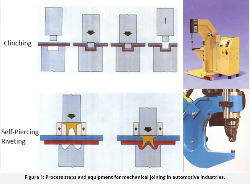
Mechanical Joining is a process for joining parts through mechanical methods, which often involve threaded holes. Joining parts using screws or nuts and bolts are common examples of mechanical joining. The threaded holes employed for mechanical joining are vulnerable to fractures. In ductile materials, the fracture can come from fatigue, while in brittle materials, the fracture can simply result from mechanical overloading. Thus, mechanical joints must be designed with fatigue failure and brittle fracture in mind. Another issue to be considered when designing mechanical joints is galvanic corrosion, which is a type of corrision that affects different types of metals that are in contact with each other.
3) What is Resistance welding & its application in the automotive sector?
Resistance welding-
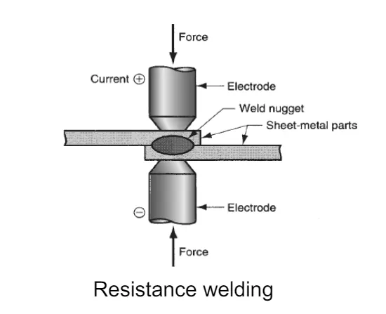
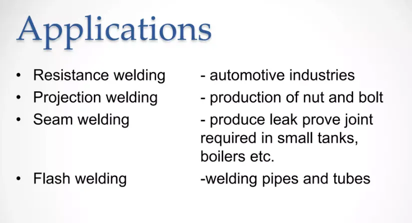
Resistance welding is the joining of metals by applying pressure and passing current for a length of time through the metal area which is to be joined. The key advantage of resistance welding is that no other materials are needed to create the bond, which makes this process extremely cost effective.
There are several different forms of resistance welding (e.g. spot and seam, projection, flash, and upset welding) which differ primarily by the types and shapes of weld electrodes that are used to apply the pressure and conduct the current. The electrodes, typically manufactured from copper based alloys due to superior conductive properties, are cooled by water flowing through cavities inside the electrode and the other conductive tooling of the resistance welding machine.
Resistance welding machines are designed and built for a wide range of automotive, aerospace and industrial applications. Through automation, the action of these machines is highly controlled and repeatable allowing manufacturers to staff production readily.
How Does Resistance Welding Work?
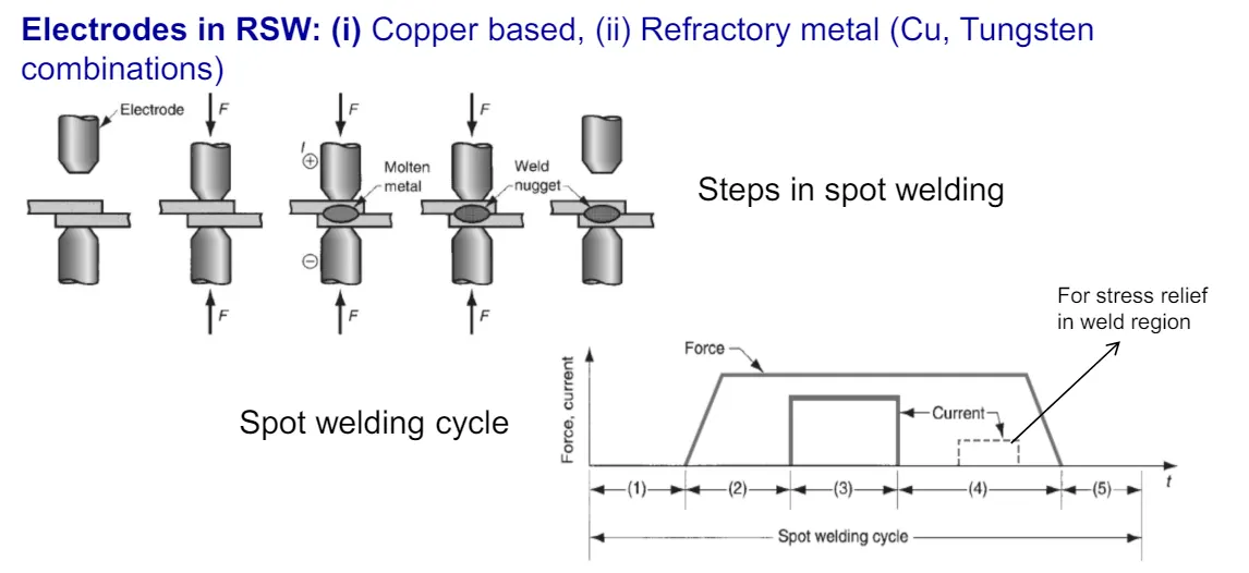
Resistance welding is generally used to join two plain metal work pieces together. An electric current is delivered to the metal sheets (or any work pieces being joined) through weld electrodes which apply force to the sheets. This force is then converted to heat. The heat is generated so that it melts the metal at the point where they join – the point of ‘resistance’ between the faying surfaces. The electrode then extracts heat from the molten weld area which forms a weld nugget at the point where it solidifies. A force is applied before, during and after a current is applied, which confines the contact area.
Types of Resistance Welding
There are many resistance welding processes with different uses, such as spot welding, seam welding, and butt welding. Each one has a different specific welding application that makes it optimal for a particular situation.
1. Resistance Spot Welding
Resistance spot welding has been used extensively in the automotive industry for the joining of steel and in the aerospace industry for airframe components made from aluminium alloys. It is one of the oldest and simplest forms of resistance welding, in which a weld nugget is produced by passing an electric current between the two metal components whilst they are held together between electrodes, typically made from copper-based alloys due to its superior conductive properties.
2. Resistance Seam Welding
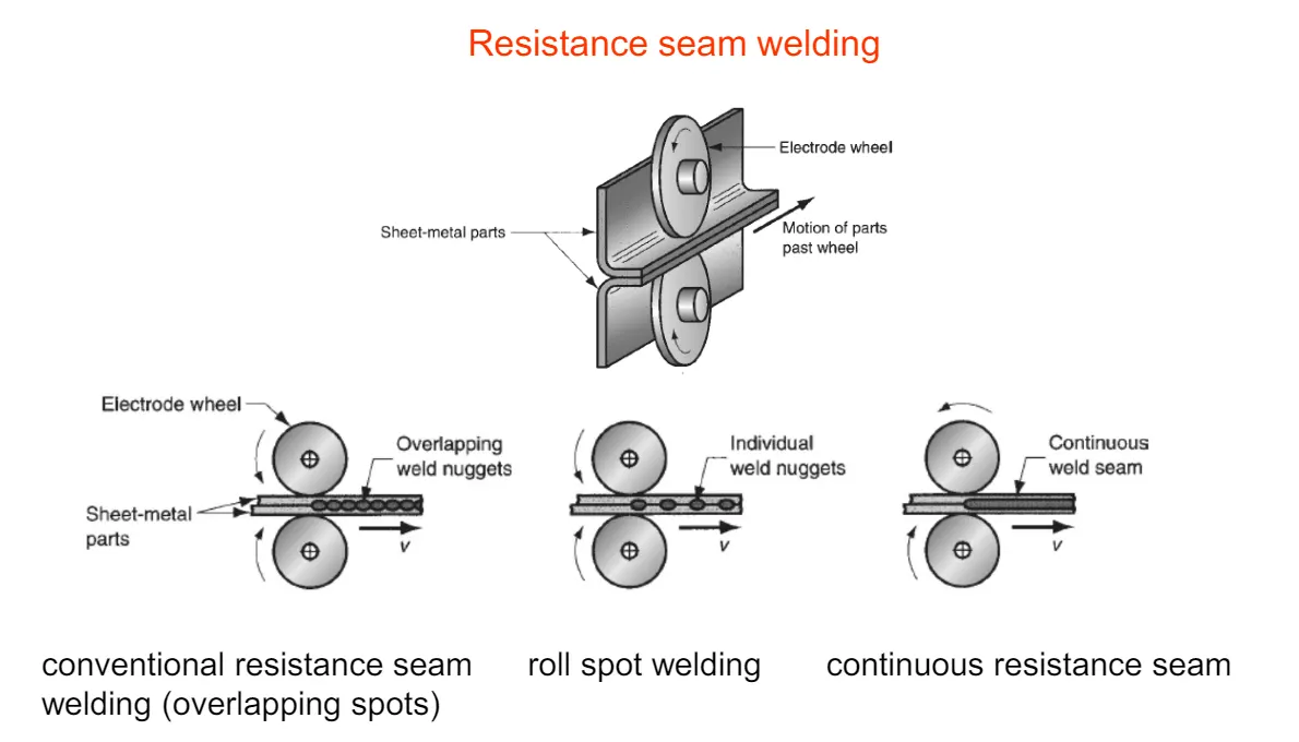
Resistance seam welding is a variation of the standard spot welding form, however instead of spot one nugget, a series of overlapping nuggets is produced. This is usually done by replacing the conventional spot welding electrodes with wheels, which turn as the parts are fed between them. The process thus produces a continuous welded seam rather than a single spot. Seam welding is often used in the production of thin sheet, leak-tight containers such as fuel tanks, and is generally unsuitable for welding aluminium.
3. Resistance Projection Welding
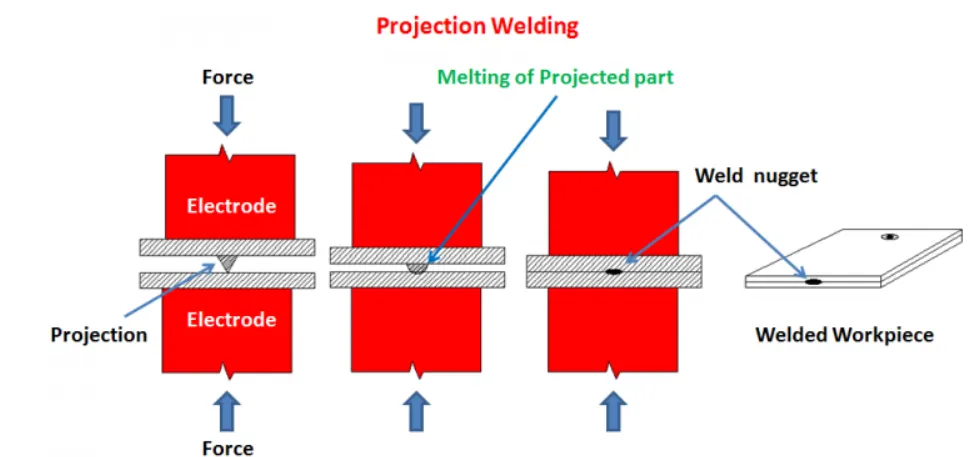
Resistance projection welding is a form of resistance welding where the electricity, force, and weld time are concentrated on raised ‘projections’ across the surface. Projection welding is generally used for welds using thicker materials than the thinner metal pieces that spot welding is usually required for, and often not metals. It is used primarily in the electrical, automotive and construction industries.
4. Resistance Butt Welding
Resistance butt welding is a process in which the two components of similar cross section can be joined together in one operation that takes place simultaneously across the entirety of the affected object, rather than just in small spots. The welding application of butt welding is often in wires and rods with small diameter measurements, generally up to about 16mm diameter.
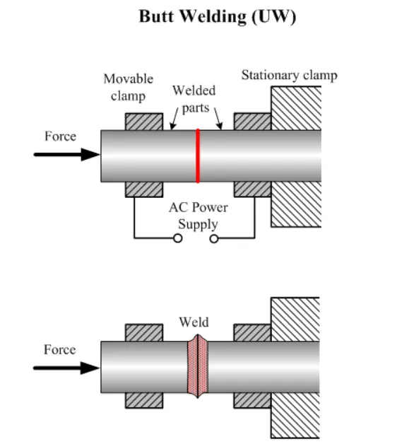
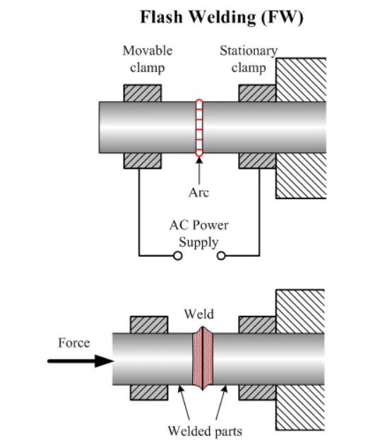
5. Flash Butt Welding
Flash butt welding is similar, but in this case the energy transfer is primarily provided by the resistance heat arising from the parts themselves. This is a faster type of resistance welding where the welder joins the parts by applying some pressure, then by passing a heavy current through the joint which burns away surface irregularities. After the weld has generated enough heat, the parts are connected by applying heat and pressure simultaneously. This produces a forge butt weld with no melted metal remaining in the joint.
Advantages
- Similar and dissimilar metals are capable of being welded
- Highly automated
- Efficient with high production rate and high welding rate
- Cost-effective
- Environment-friendly, produces little waste or pollution
- No need for filler metal or extraneous materials such as rods, fluxes, inert gasses, oxygen, or acetylene are required
Disadvantages
- Complex and often high-cost machinery – a resistance welding machine generally requires a high level of technically trained personnel to use
- The thickness of the work piece is often limited
- It is less efficient for high conductive materials
- High electric power required
4)What is fusion welding & types of fusion welding with its application in the automotive sector?
- Fusion welding is a process that uses heat to join or fuse two or more materials by heating them to melting point. The process may or may not require the use a filler material. External application of pressure is not required for fusion welding processes, except for resistance welding, where substantial contact pressure is required during welding for sound joining.
- Fusion welding processes can be grouped according to the source of the heat, for example, electric arc, gas, electrical resistance and high energy.
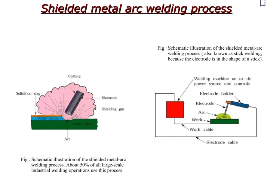
Shielded Metal Arc Welding (SMAW)
- also known as manual metal arc welding (MMA or MMAW), flux shielded arc welding or stick welding.is a manual arc welding process that uses a consumable electrode covered with a flux to lay the weld.
- An electric current, in the form of either AC or DC from a welding power supply, is used to form an electric arc between the electrode and the metal to be joined. The workpiece and the electrode melts forming a pool of molten metal that cools to form a joint. As the weld is laid, the flux coating of the electrode disintegrates, giving off vapors that serve as a shielding gas and providing a layer of slag, both of which protect the weld area from atmospheric contamination.
- Because of the versatility of the process and the simplicity of its equipment and operation, shielded metal arc welding is one of the world's first and most popular welding processes. It dominates other welding processes in the maintenance and repair industry, and though flux cored arc welding is growing in popularity, SMAW continues to be used extensively in the construction of heavy steel structures and in industrial fabrication. The process is used primarily to weld steels (including stainless steel).
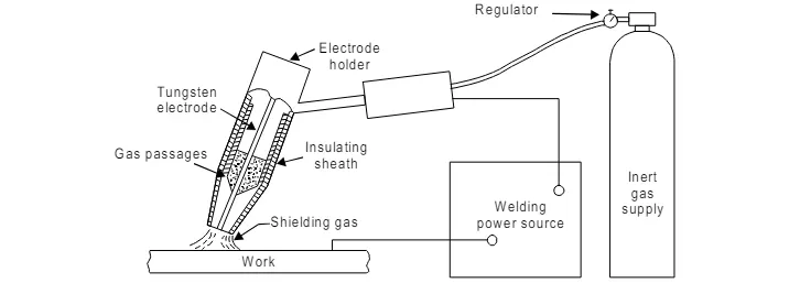
TUNGSTEN INERT GAS Welding(TIG)
In this process a non-consumable tungsten electrode is used with an envelope of inert shielding
gas around it. The shielding gas protects the tungsten electrode and the molten metal weld
pool from the atmospheric contamination. The shielding gases generally used are argon,
helium or their mixtures.
Electrode materials
The electrode material may be tungsten, or tungsten alloy (thoriated tungsten or
zirconiated tungsten). Alloy-tungsten electrodes possess higher current carrying capacity,
produce a steadier arc as compared to pure tungsten electrodes and high resistance to
contamination.
Electric power source
Both AC and DC power source can be used for TIG welding. DC is preferred for welding
of copper, copper alloys, nickel and stainless steel whereas DC reverse polarity (DCRP) or AC
is used for welding aluminium, magnesium or their alloys. DCRP removes oxide film on
magnesium and aluminium.
Inert gases
The following inert gases are generally used in TIG welding:
1. Argon
2. Helium
3. Argon-helium mixtures
4. Argon-hydrogen mixtures
Tig Nozzle
The nozzle or shield size (the diameter of the opening of the shroud around the electrode)
to be chosen depends on the shape of the groove to be welded as well as the required gas
flow rate. The gas flow rate depends on the position of the weld as well as its size. Too high
a gas consumption would give rise to turbulence of the weld metal pool and consequently
porous welds. Because of the use of shielding gases, no fluxes are required to be used in inert
gas shielded arc welding. However for thicker sections, it may be desirable to protect the root
side of the joint by providing a flux. The process is generally used for welding aluminium,
magnesium and stainless steel.
MIG Welding
MIG Welding is the most widely used arc welding technique in BIW joining.
Aluminum parts have been largely been joined by means of MIG (Metal Inert Gas) welding in lightweight car manufacturing.
This technique is principally used to make joints between castings and extruded sections, as well as sheet-metal parts.
Advantages
- High-strength weld with great appearance
- Little need for sanding or cleaning
- Relatively quicker process due to operability at a continuous rate, due to use of shielding
- MIG welding can be used on any metal surface and has the capability to weld materials as thin as 26-gauge.
Metal Inert gas Welding
MIG welders use a tool called a spool gun, which feeds a spooled wire electrode at a selected speed. The gun also emits a shielding gas as it lays the weld. This gas protects the weld area from atmospheric gases such as nitrogen and oxygen, which can cause problems if they come in contact with the electrode, the arc, or the welding metal.
The Final result of an optimal MIG Welding process
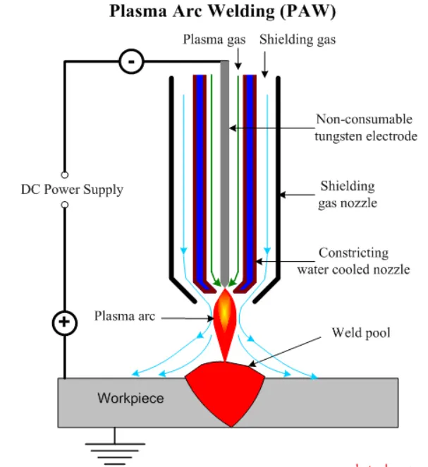
plasma arc welding: This process uses an electric arc created between an electrode and the torch nozzle. The electric arc ionises the gas (usually argon) in the chamber creating what is called a 'plasma.' It is then forced through a fine bore copper nozzle that constricts the arc and directs it to the workpiece, allowing the plasma arc to be separated from the shielding gas (which is usually made from a mixture of argon and hydrogen).
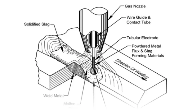
Flux Cored Arc Welding (FCAW). Developed as an alternative to SMAW, this process uses a continuously fed consumable electrode with a flux and a constant voltage or constant current power supply. Sometimes using a shielding gas this process can also just use the flux to provide protection from the atmosphere.
Automobile application of arc welding -
- Arc welding is used to weld the chassis parts in automotive industry.
- Arc welding wire for automotive steel sheets
Solid wires suitable for robot welding that generate comparatively small amounts of slag and fume are chosen for welding of automotive parts.
- Arc welding is used to weld the body parts in Automotive industry-
Low heat input welding of thin steel sheets Prevention of burn-through due to excessive heat input is important in the welding of car body parts of thin sheets. For this rea-son, thin welding wire with a diameter of 0.9 mm, which enables stable welding at low currents, and low-heat-input welding power sources
- TIG welding is used to join thin stainless steel parts & various piping parts in automobile industry.
- MIG welding is used for the repairing work in automobile industry weather they are small, big, light or heavy.
(5)What is the 3-2-1 principle?
-The 3-2-1 Principle
What is it?
- A fundamental concern in metalworking is locating the part to be machined, punched, bent, or stamped relative to the work platform (fixture). For example, a CNC machine tool starts its process at a specific point relative to the fixture and proceeds from there. Hence, the accuracy with which a part is machined is quite dependent on the accuracy with which it is positioned in the fixture.
- Accurate locating of not just one part, but each and every part that is loaded into the fixture is crucial. Any variation in part location on the fixture adds to the dimensional tolerance that must be assigned to the finished parts.
- Additionally, the method of supporting and securing the part in the fixture affects not only dimensional tolerances, but surface finishes as well. This is true because improper supporting or clamping can temporarily or permanently deform the part.
- Techniques for supporting and clamping must be considered together with the method of locating in order to assure repeatability from part-to-part.
- Locating of a part to be machined is a three-step process:
1. Supporting
2. Locating (positioning)
3. Holding (clamping)
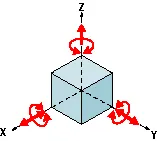
The Locating Process: Degrees of Freedom
In order to completely specify the position in space of a three-dimensional
object (such as the cube that’s shown), we refer to six coordinates:
- Translational position along the X-axis
- Translational position along the Y-axis
- Translational position along the Z-axis
- Rotational position about the X-axis
- Rotational position about the Y-axis
- Rotational position about the Z-axis
- These six coordinates are known as the six degrees of freedom of a three-dimensional object. As the double-headed arrows indicate, the translational and rotational positions can vary in either direction with respect to each of the three axes.
-To completely prevent movement, all six degrees of freedom must be restricted.
The Locating Process: 3-2-1 Method
- We have two objectives when mounting a part in a fixture for machining:
1. Accurately position the part at the desired coordinates.
2. Restrict all six degrees of freedom so that the part cannot move.
- A widely used method of accomplishing these two objectives uses the 3-2-1 principle, so-called because it entails three steps that employ three, then two, then one fixed points of known location. Since that adds up to six fixed points, it’s also known as the six point method.
- In the three steps of the 3-2-1 method, three mutually perpendicular planes, called datum planes, are introduced, one at each step. These three planes define the workpiece position, and together with opposing clamping forces fully constrain the part. Let’s take a look at the details of the 3-2-1 method.
First Plane
- Geometry tells us that three points are required to define a plane. This is the "3" in 3-2-1. So, three specific points are used to define the first plane.
- Fewer than three points cannot define a plane, and in the real world dimensional tolerances mean that four or more points will not be coplanar. A real-world, less than ideally perfect part placed on four or more reference points will, in fact, rest on only three of the points due to its less than perfect surface.
- Different parts may rest on different combinations of three points, resulting in variation between finished parts.
- A stool can be used to illustrate this concept. A two-legged stool would certainly be unstable. A three-legged stool sits rock-solid. A four-legged stool is often found to rock.
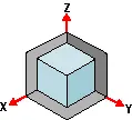
- In the illustration, a three dimensional part, represented by a cube, is placed on a datum plane defined by three support points. The part’s six degrees of freedom have now been reduced to three. It can still move along the X or Y axes, and it can still be rotated about the Z axis. (The part cannot move along the Z axis because it is held against the plane by clamping force.
TIPS
- Use the largest surface of the part for the first ("primary") reference plane.
- Position the three support points as far apart as possible.
- If more than three support points are required to prevent deflection, make the additional points adjustable.
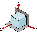
Second Plane
- A second plane, if it is perpendicular to the first, can be defined by two points, the "2" in 3-2-1.
- The part is now constrained to one degree of freedom: movement along the Y axis. (The part cannot move along the X or Z axes because it is held against the planes by clamping force.)
Third Plane
- A third plane, if it is perpendicular to both of the first two planes, can be defined by one point, the "1" in 3-2-1. The part is now entirely constrained. It cannot move along or rotate about the X, Y, or Z axes. (Remember that the part is held against each of the three planes by clamping force.)
TIPS
- If more than one support point is required to prevent deflection, make the additional points adjustable.
Machined is Best
It’s best if the workpiece surfaces intended to contact the support points are machined. Cast surfaces are usable, but then tend to create tolerance problems. Machined holes are the number one choice. Two machined holes can be used to eliminate all but one degree of freedom.
Repeatability
- Repeatability is a paramount concern. It means that each part should be nearly identical to each other part coming off the same fixture. "Nearly identical" actually has a specific, quantifiable meaning: key dimensions of all parts produced on the same fixture must fall within defined tolerances.
- In order to stay within tolerances, it’s best if the workpiece surfaces intended to contact the support points are machined. Cast surfaces are usable, but they tend to create tolerance problems. Machined holes are the number one choice, because two machined holes can be used to eliminate all but one degree of freedom.
- The next best feature to use for consistent locating is machined surfaces at right angles. The "machined surface" desired here can simply be a tab or small flat specifically included for locating purposes.
- Repeatability is achieved through application of the 3-2-1 method to the three aspects of the locating process:
1. Supporting
2. Locating (positioning)
3. Holding
Supporting
- The part is supported from "below" with reference to the Z axis. (Introduction of the first reference plane.)
- Gravity positions the part against the support locator.
- Provide adjustable auxiliary support points as needed to prevent deflection.
- Vertical location with respect to the fixture is now established
- The part is positioned horizontally, in the X-Y plane. (Introduction of the second and third reference planes.)
Holding
- The part is clamped against fixed locators. Therefore, a known and unvarying position of the part is maintained with respect to the X, Y, and Z axes.
- One strap clamp or clamp arm will restrict the workpiece in three dimensions due to friction between the workpiece and clamp. However, friction alone may not be enough to prevent the workpiece from moving during machining.
- Cutting forces will not move a properly supported and clamped part.
Locating
- The part is positioned horizontally, in the X-Y plane. (Introduction of the second and third reference planes).
Summary: Clamping rules of thumb
- Define three reference planes on the workpiece and fixture.
- Provide one opposing clamping force opposite each plane to restrict movement.
- When in doubt, rely on additional cylinders to take up uncertainty.
6)Define Body coordinate system?
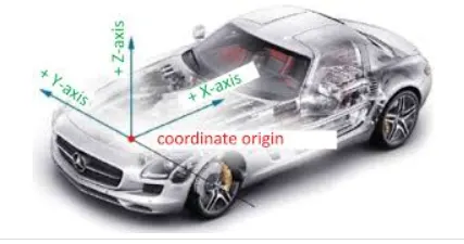
Coordinate system is a reference system Consisting of a set of point, Lines & surfaces used to define position of point in space either in 2 or 3 dimensions.
In general BCS is also called as car line or Body line
Car lines are the (Grid lines) shown on the fixture, which virtually represent the same location in the BIW. All the car line on fixture display the coordinate at corner for reference. With these lines one can easily relate the, location in BIW.
Some times single coordinate hole is given in the fixture, that also represent the car line coordinates, from that reference point fixture is made and can be inspected. Body coordinate are mentioned near the hole.

Maintaining X,Y & Z co-ordinates in fixture is a very important factor.
-We should try that the co-ordinates of locating and clamping points should not be in three decimal (e.g. X=100.124, Y=245.127, Z=450.458).
They should be in the whole nos. or max upto 1 decimal . Once these co-ordinates are maintained automatically the BIW base structure is maintained.
All vehicle product drawings are identified numerically relative to three vehicle planes Description shown below.
1. ( X ) It is in width of BIW – 0 X - is Body Center Line
2. ( Y ) It is in length of BIW – 0 Y is Near Front Bumper
3. ( Z ) It is in Height of BIW - 0 Z is about Center of Wheel
7)Elaborate Body plane system & its essentials.
body planes are reference planes in an automotive car. the planes are used to define the GD&T of all car parts in a automotive domain.
body planes are 3 mutually perpendicular imaginery palnes . these are generally considered to be present at the driver position or somtimes at the engine location or at front end of the car, depending on the customer.
the mesurements from the body planes to the parts are called as bodyline dimensions .
these body planes are called as
FOL- front "O" line
COL-center "O" line
BOL-bottom "O" line
the measurement along FOL or X axis is called as F/A front Aft
the measurement along COL or Y axis is called as C/C cross car
the measurement along BOL or Z axis is called as U/D up down