Week 2:- BiW Fixture Basics Challenge
1.The above figure shows the process involved in process execution activities. It is a general activity that is involved in BIW fixture & Tooling.It is the starting phase of every project.
1.RFQ
A request for quotation is a business process in which a company or public entity requests a quote from a supplier for the purchase of specific products or services.
Technical offer will be submitted by the customer based on technical offer we prepare our offer based on customer requirements.
The customer needs and other details will be in the RfQ
2.Spec discussion meeting
After rfq the commercial offer letter will be received from the customer.
In this time required for data study, 3D design concept, simulation validation, quality check, 2d drawing release, bought-outs, manufacturing, assembly, installation & commissioning will be discussed and prepared in the technical offer.
Based on the commercial offer the technical offer will be finalized
3.Offer submission
After discussion in the meeting the offer from the company will be submitted to the customer. The customer will check with other suppliers based on the given offer then he finalizes based on quality,standard,offers,cost.
4.LOI/PO receipt
It is the receipt will get from the customer end to start the work po is nothing but purchase order.
After PO is received the schedule should be prepared from the company side.
5.Schedule preparation
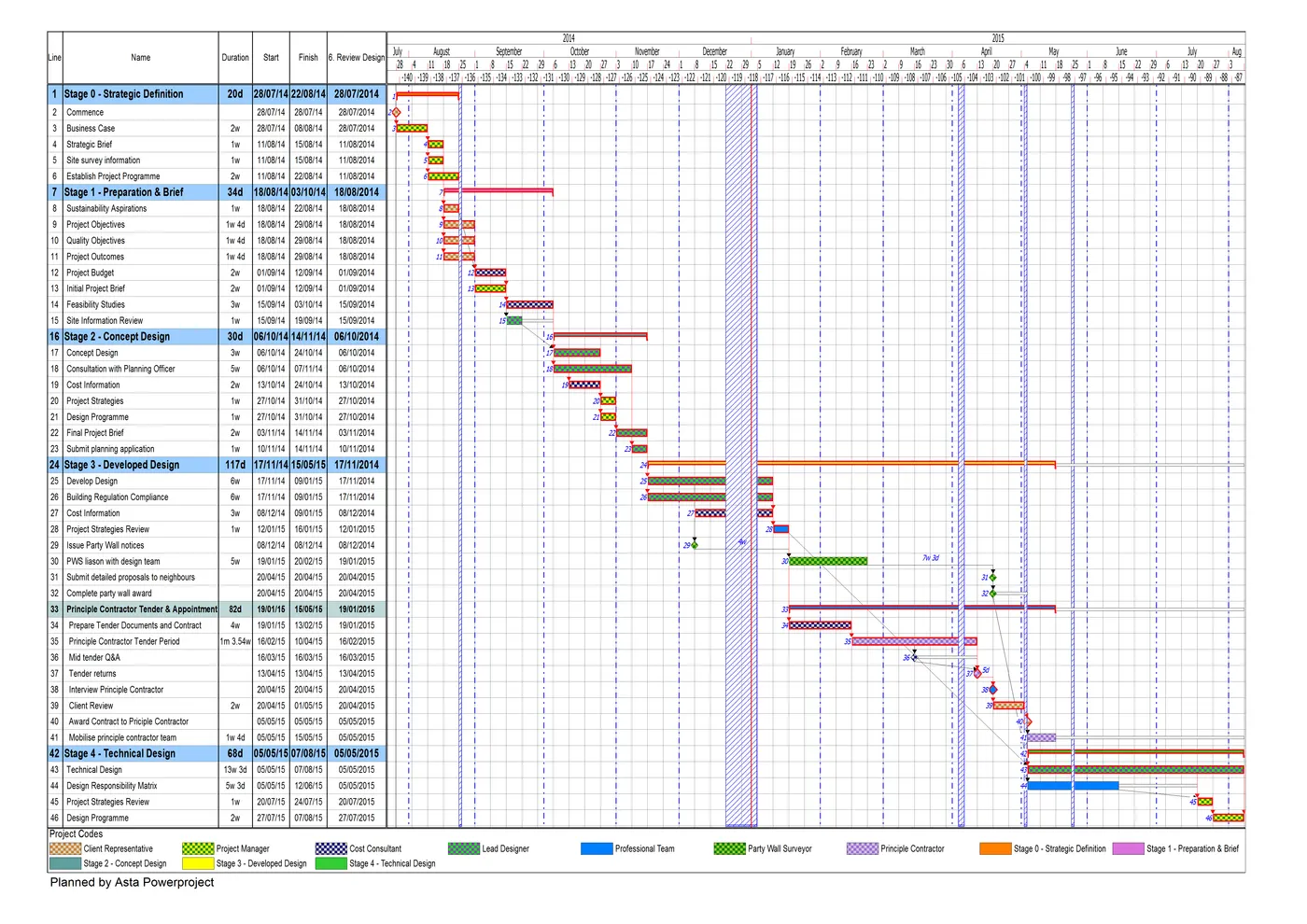
Once the PO released from the customer, we will be working on the preparation of the schedule which should be matched our planned commitment in the technical offer/customer required time.Schedule preparation is nothing but dividing the different activities like kick-off meeting, design data study, DAP, simulate, Quality check 2D detailing, drawing check, Release of BOM, Manufacturing, bought outs of electrical & mechanical components, Assembly of the fixture, paint, trial run out, installation and commissioning at the customer end, etc.These activities will be traced in the schedule preparation chart.The date-wise schedule should be matched the committed date. Otherwise have to revise the schedule and prepare accordingly by discussing it in the meetings.
6.Bom
It is basically some standard elements will be purchased before design for the bill of matrial will be prepared.
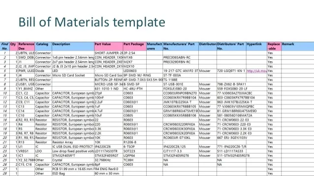
In bom the cost and quantity will be mentioned based on materials will be purchased.
7.Design concept preparation
After receiving the details from the customer based on that the concept is designed and concept study is carried out.The concept preparation would include the process like load act on panels, clamping process, which spot should be welded first, travel of the gun.
In concept preparation the cycle and other thing will be studied.Cycle time study includes min per shift, No. of shifts, No. of days per year, No. of component per year, the total number of minutes.
In design concept preparation, the design of the layout is been prepared at a very initial level which gives the information of placements of robots and fixtures.
8.Customer approval
After design concept preparation the design is discussed with the customer.
After design concepts, the customer will review the design concepts.
After design is discussed with the customer if there changes to be done will be done and further process is carried out.
9.Detailing and dwg
Once the customer approved the process, the detailing of the fixture parts which is to be manufactured has been done by giving appropriate dimensions and GD&T symbols.
All the dimensions which are necessary for manufacturing should be included with GD&T in the drawing before releasing the drawing to the manufacturing team.
10.Manufacturing and Bom ordering
The materials after designing is order some of the materials are cylinders, sensors and other parts required for manufacturing.
The order is done based on design specifications.
11.Mechanical/electrical assembly
The parts will be manufactured and the assembly is carried out based on the design specification.
12.Quality inspection
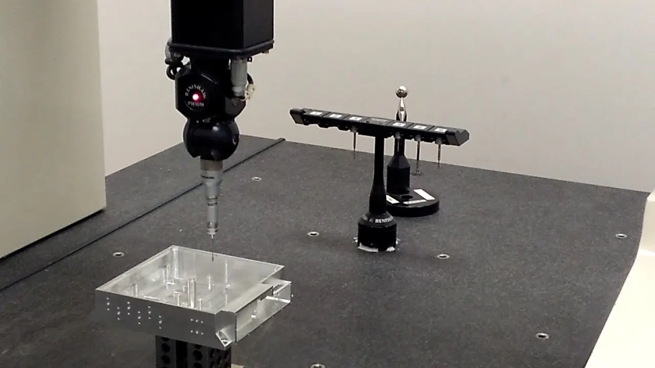
After manufacturing the inspection will be carrird out with cmm and other tools
Accuracy of the fixture and other other things are inspected
13.Internal trial and testing
After the inspection the fixture tested how it works and accuracy of the fixture
Based on that we can get to know the clamping is proper or not and also assemble of the fixture is proper or not.
14.ONline trial
The trail will be done automatically made through the control panel. The process sequence of operation is checked as by the designed way. Welding feasibility is there or not.IT is done through electrical signals
15.Packaging
It is basically packing of fixture without damage. After approval of QC, the packaging is been done as per standards. Certain companies follow certain packaging standards, So the packaging should be one as per customer standards.
16.Dispactch
The fixture is dispatched to the customer with the required documents.
17.Instaliation as per layout
It will be designed at the start of the design.
Installiation of fixture is done as layout .It basically gives the information of robots and fixture to be installed in specific place. According to the design, the installation & commissioning team will install the fixtures.
18.Trials and training at customer
As per mentioned in the technical offer the fixture can work 8 hr shift 100 units manufactured for example.
Training the operator how the process is going on and also sequence of the fixture.
19.Buy off Metting
The customer will go through the fixture if any extra modification is required or the in design some changes to be done the customer will rise the quotation.
20.Final handover
The fixture handed to the customer and 3d and 2d and also some of the other documents submitted to the customer for the company side. Documents are like clamp validation, sequence sheets, ergo validation documents and also bom.
3.Resistance welding
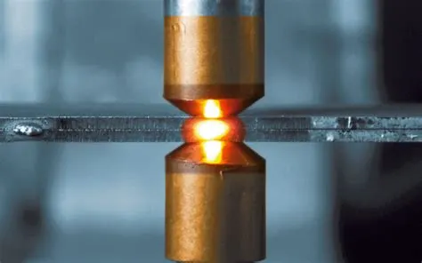
Resistance welding is a welding technology widely used in manufacturing industry for joining metal sheets and components. The weld is made by conducting a strong current through the metal combination to heat up and finally melt the metals at localized point predetermined by the design of the electrodes and/or the workpieces to be welded. A force is always applied before, during, and after the application of current to confine the contact area at the weld interfaces and, in some applications, to forge the workpieces.
Types of resistance welding
1.Resistance Spot Welding
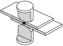
Spot welding is a process for joining metal sheets by directly applying opposing forces with electrodes with pointed tips. The form of the electrodes localized the current and the heat generation. Thus the electrode tip contact area usually define the weld nugget size.
Spot welding is the predominant joining process in automotive industry for assembling the automobile bodies and large components. It is also widely used for manufacturing of furniture and domestic equipment.
2.Resistance seam welding
Seam welding is a resistance welding process for joining metal sheets in continuous, often leak tight, seam joints by directly applying opposing forces with electrodes consisting of rotary wheels. The peripheral shapes of the electrode wheels concentrate the current and the heat generation.
Seam welding is mostly applied in manufacturing of containers, radiators and heat exchangers etc.
3.Resistance projection welding
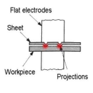
Projection welding is a process for joining metal components or sheets with embossments by directly applying opposing forces with electrodes specially designed to fit the shapes of the workpieces. The natural shape of the workpieces or specially designed projection localizes the current and heat generation. Large deformation or collapse will occur in the projection part of the workpieces implying high process/machine dynamics.
4.Resistance butt welding
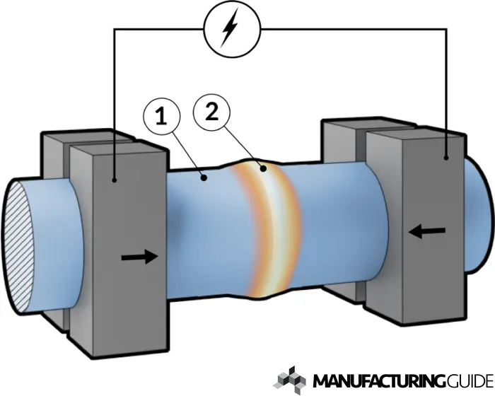
Butt welding is a resistance welding process for joining thick metal plates or bars at the ends by directly applying opposing forces with electrodes clamping the workpieces. A forging operation is applied after the workpieces are heated up. Often no melt occurs, thus a solid state weld can be obtained.
Butt welding is applied in manufacturing of wheel rims, wire joints and railway track joints etc.
Application of resistance welding
1. wire joints
2.wheel rims,
3.
2.2.Types of joining process
1.MEchaical joining
2.Metallugical joining
2.Metrullgrical joining
1.Mechanical joining process
Mechanical joining – also called joining by forming – has become interesting for the automotive industry due to the request to reduce fuel consumption and thereby emissions.
In order to reduce weight on the car body, the usage of lightweight materials in the body-in-white application has increased.
All mechanical joining methods are cold forming techniques. One general benefit for all mechanical joining methods is the mobility of the material after joining. At the same time mechanical joining offers an impressive strength.
TYpes of mechanical joining process
1.Riveting
Riveting is the general term for joining with rivets / fasteners.The principle of riveting is to join two or more plates mechanically by a joint. The joint is placed in a hole in the plates and forced mechanically to deform and thereby lock the plates.
Different types of riveting
1.SElf piercing riveting
2.Blind riveting
3.Punch riveting
4.Clinch riveting
1.Self piercing riveting
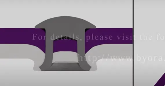
The principle is that it fastens together two or more sheets of material mechanically with a self-piercing rivet. The rivet pierces the top sheet and the joining is achieved when the rivets pierces the bottom sheet partially, deforms the material into the die, and thereby forms a mechanical interlock. Often a layer of adhesive is used to keep the sheets in place while riveting.
2.HEmming
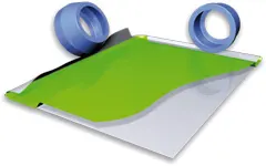
Hemming is a forming operation in which the edges of the sheet are folded or folded over another part in order to achieve a tight fit. Normally hemming operations are used to connect parts together, to improve the appearance of a part and to reinforce part edges.
In car part production, hemming is used in assembly as a secondary operation after deep drawing, trimming and flanging operations to join two sheet metal parts (outer and inner) together. Typical parts for this type of assembly are hoods, doors, trunk lids and fenders.
Types of hemming process
1.Conventinal die hemming
2.Roll hemming
3.Soldering
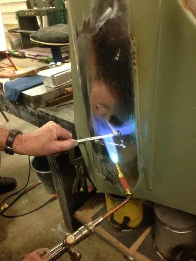
Soldering is used to join two or more metal materials together using filler solder material. In this process, the solder material used to join other metals does not heat to a high temperature. In other words, solder material becomes a liquid at a relatively low temperature. It is usually heated to a temperature below 4500C. During early days, most of soldering materials contained lead (Pb), but now the use of lead-free solders have been implemented due to environmental and health concerns.
4.Brazing
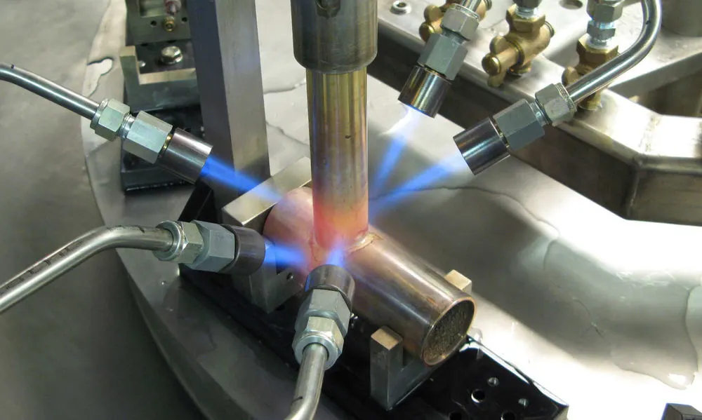
Brazing joins metal surfaces together with a filler metal which has a low melting point. The process uses capillary action wherein the homogenous liquid flow of the filler material bonds with the base metals.A unique quality in the brazing process is that it keeps the mechanical properties of the metals which are useful in applications such as silver brazing or other similar metals.
One of the most crucial steps in the metal joining process is the cleaning of the base metal surfaces. Emery cloth or wire brush are both great tools to remove contaminants.
Having calculated joint gaps for the liquid filler metal to achieve surface tension with the workpiece, the brazing operation begins with properly positioning the assembly. A torch is normally used to slowly heat the workpiece’s metal surface and filler metal into its brazing temperature.
4.Adhesive Bonding
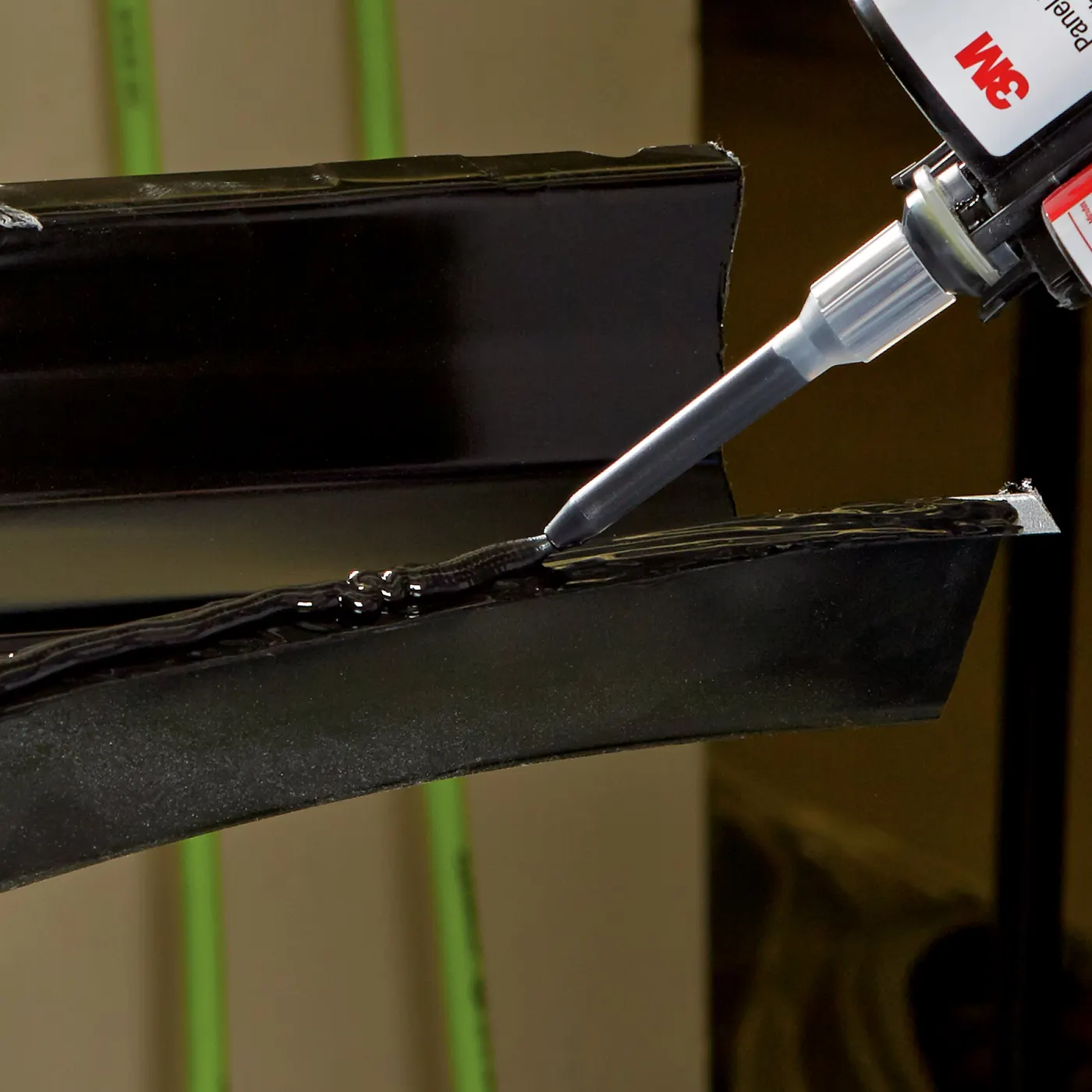
Adhesive bonding is a joining technique to join materials by applying an intermediate layer of adhesives or glues. This joining technique involves glues, epoxies, or various plastic agents that bond by evaporation of a solvent or by curing a bonding agent with heat, pressure, or time. Adhesive bonding is similar to in that a metallurgical bond does not take place though the surfaces being joined may be heated but they are not melted.
2.Metallugical joining
1.Welding
It is basically a joining process where two metals are joined by heat. Welding is a fabrication process whereby two or more parts are fused together by means of heat, pressure or both forming a join as the parts cool. Welding is usually used on metals and thermoplastics but can also be used on wood. The completed welded joint may be referred to as a weldment.
Different types welding
1.Arc welding
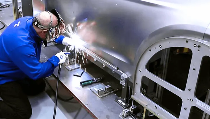
The arc process uses a variety of rods which have different strengths, weaknesses and uses which can impact weld quality. The rod is connected to the welding machine and a current is passed through to join work pieces together.
Process of arc welding
- Strike the arc. This is the process of creating an electric arc between the electrode and the workpiece. ...
- Move the arc to create a bead. The bead is the metal from the melting electrode flowing together with molten metal from the base metal to fill the space between the pieces being joined by welding.
- Shape the weld bead.
Types of arc welding
1.Manual metal arc welding
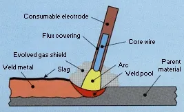
he process allows only short lengths of weld to be produced before a new electrode needs to be inserted in the welding electrode holder. Weld penetration is low and the quality of the finished weld deposit is highly dependent on the skill of the welder.
2.Metal inert gas welding(mig)
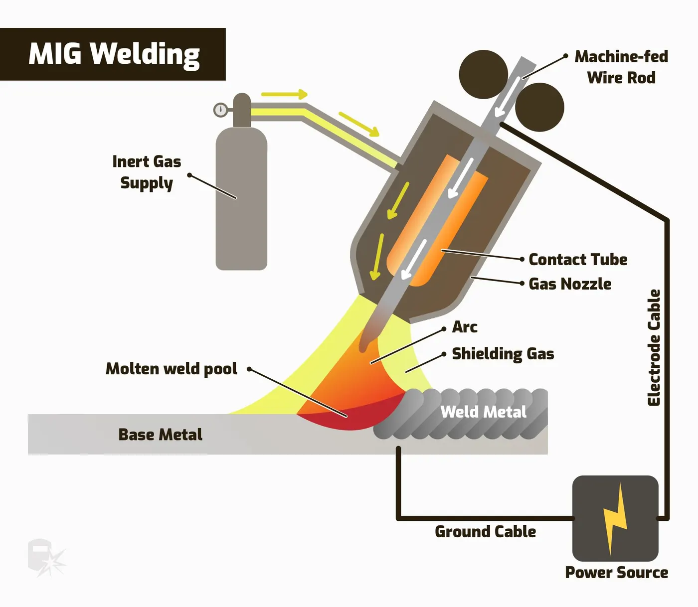
Unlike TIG, MIG welding relies on an automatic wire feeder that pushes the filler metal wire into the molten weld pool. But this filler wire is also energized, just like the tungsten electrode in TIG welding.MIG wire exits from the wire feeder, through the lead, and into the MIG gun torch. Once the wire touches the metal, an arc forms, which melts the wire and base metal.
3.Tig welding
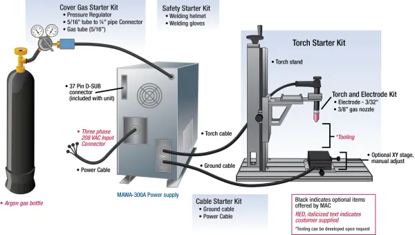
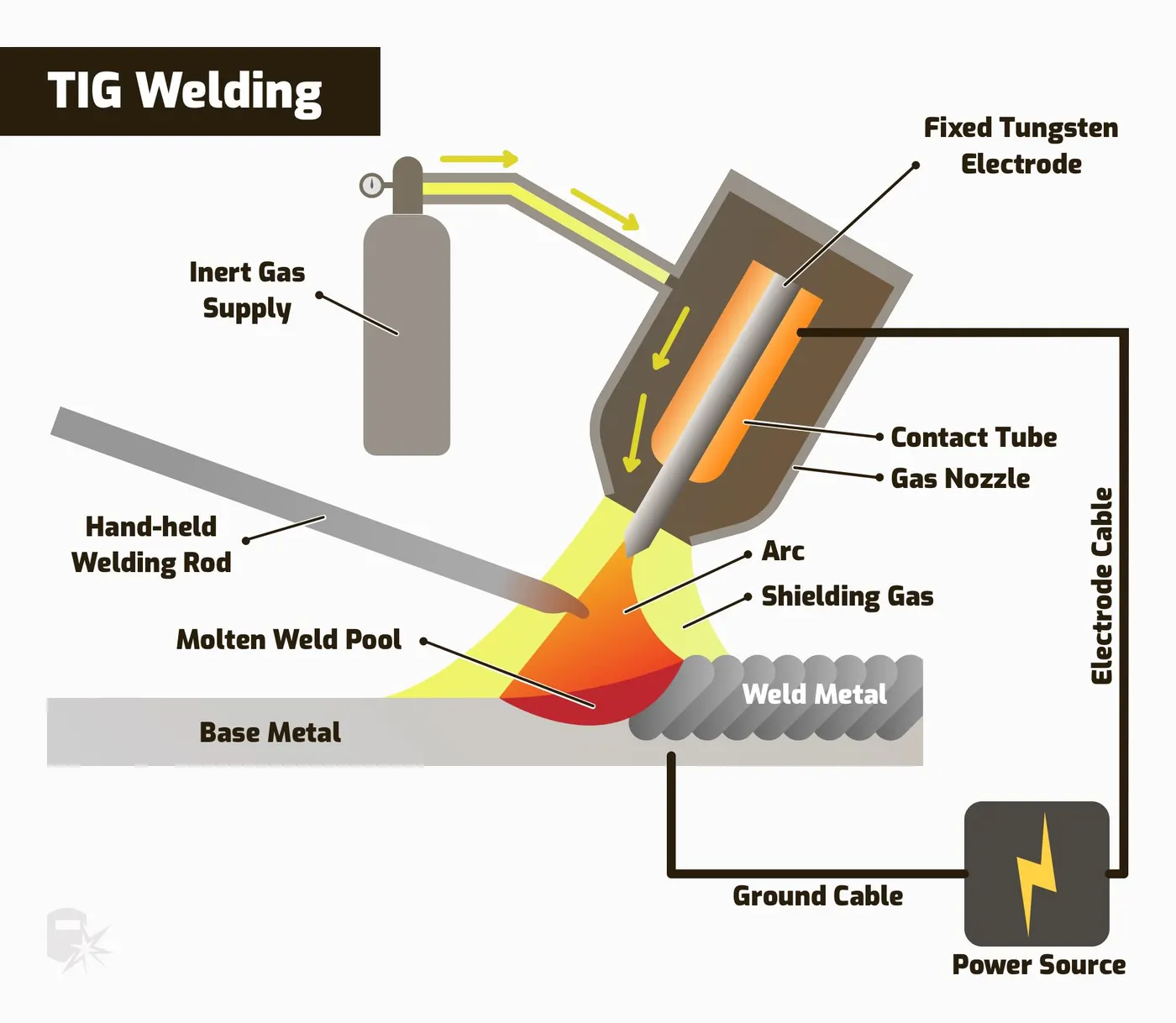
Gas tungsten arc welding (GTAW), or TIG welding, is an arc welding process that uses a non-consumable tungsten electrode to create an arc and join metal. It requires shielding gas, mostly pure argon or argon mixed with helium.
4.Submerged arc welding
A frequently-used process with a continuously-fed consumable electrode and a blanket of fusible flux which becomes conductive when molten, providing a current path between the part and the electrode. The flux also helps prevent spatter and sparks while suppressing fumes and ultraviolet radiation.
5.Plasma arc welding
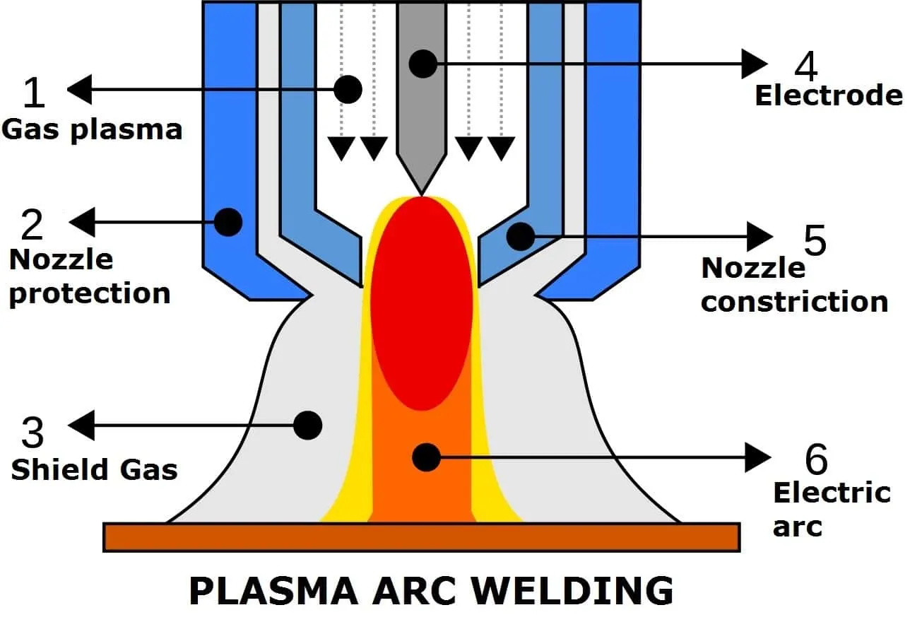
Similar to TIG, uses an electric arc between a non-consumable electrode and an anode, which are placed within the body of the torch. The electric arc is used to ionise the gas in the torch and create the plasma, which is then pushed through a fine bore hole in the anode to reach the base plate. In this way, the plasma is separated from the shielding gas
2.Resistance welding
Resistance welding is a welding technology widely used in manufacturing industry for joining metal sheets and components. The weld is made by conducting a strong current through the metal combination to heat up and finally melt the metals at localized point predetermined by the design of the electrodes and/or the workpieces to be welded. A force is always applied before, during, and after the application of current to confine the contact area at the weld interfaces and, in some applications, to forge the workpieces.
Types of resistance welding
1.Resistance spot welding
2.Resistance projection welding
3.Resistance seam welding
4.Resistance butt welding
4.What is fusion welding & types of fusion welding with its application in the automotive sector?
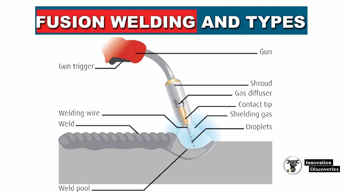
Fusion welding involves joining two or more objects by heating. When performing fusion welding, one could use filler materials, depending on the work’s nature. Welders do not apply external pressure when joining the parts.
Process of fusion welding
The heat melts the two parts that join together as they cool.one can use filler material if the gap between the two parts is extensive. Fusion welding takes part when the molten parts of the base material are combined with the molten filler. It involves applying heat to melt the material on the joining zone or develop a joint externally at the weld point.
Types of fusion welding
1.Arc welding
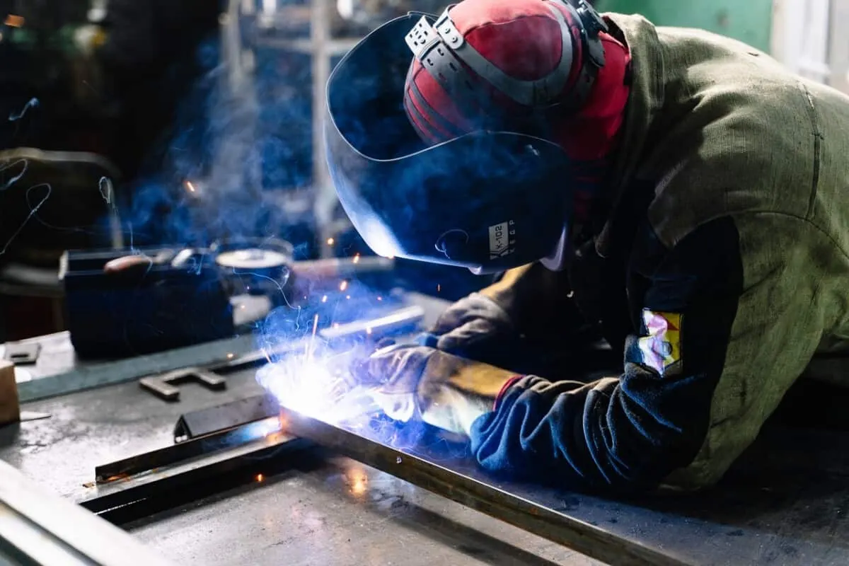
Fusion arc welding is the most common type of fusion welding. Arc welding involves connecting two or more parts using an electric art. The electric arcs produce high levels above 6000 degrees. This feature makes fusion arc welding ideal for joining hard materials. Welders can also perform arc welding underwater.
Types of arc welding
1.Shielded arc welding
2.Tungsten inert gas welding
3.Metal gas arc welding
4.Submerged arc welding
5.Plasma arc welding
6.Flux core arc welding
2.Gas welding
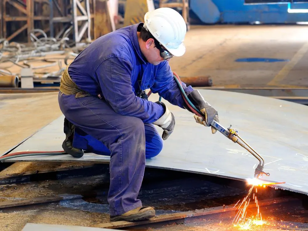
This process involves using a blowpipe held in the hand that combines both oxygen and acetylene gas to produce a flare. It is a solvent-based fusion welding that requires a flame to meltdown and connects the surface. Oxygen acts s the primary fuel source for the flame.
This welding type bases its foundation that there must be oxygen to produce fire. The oxygen allows it to create an extremely hot flame that surpasses 4500 degrees Fahrenheit.
3.Electron Beam welding
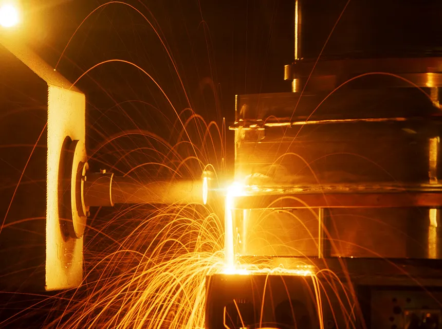
This high-energy welding uses high-velocity electrons to join two different materials. The process takes place under normal atmospheric pressure, and the electrons produce heat in the material as they enter. The welts are mostly deep and narrow.
4.Laser beam welding
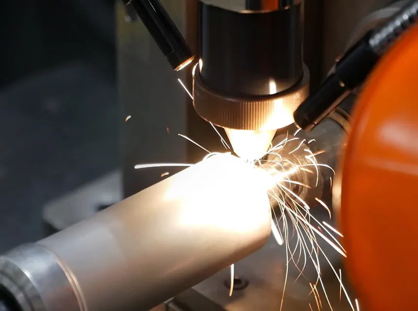
Laser beam welding utilizes a laser beam as the primary source of heat. The use of the laser beam helps maintain a highly focused energy source that is used to join different metal pieces of plastics. It uses light energy to produce heat. The rig produces dissipated light that warms the surface with every single blast.
Application of fusion welding
1.Welding of boby structures: Roof ,Floor, Side panels.
2.Welding of exhaust system : Muffler , catalytic converter, exhaust pipes.
3.Welding of fuel tanks: Filler neck , Fuel pump , Fuel lines.
4.Welding of suspension components : Control arms, swag bars, struts.
5.Welding of engine components : Cylinder head, engine blocks, Oil pan etc.
5. 3-2-1 Principle
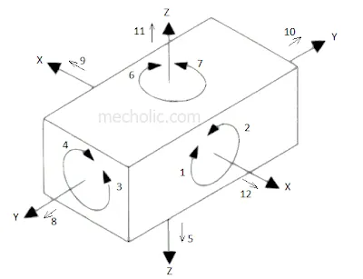
3-2-1 principle is used to constrain the given part in 12 degree of freedom .The 3-2-1 principle states that the six locators are sufficient to restrict the required degree of freedom of any workpiece. In this, motion is restricted using clamps and locators. A three-pin base can restrict five motions and six pins restrict nine motions.3-2-1 principle basically restrict the work piece without moving in any axis.
Purpose using 3-2-1 principle
1. Accurately position the part at the desired coordinates.
2.Restrict all six degrees of freedom so that the part cannot move.
Degree of freedom
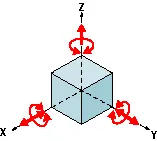
- Translational position along the X-axis
- Translational position along the Y-axis
- Translational position along the Z-axis
- Rotational position about the X-axis
- Rotational position about the Y-axis
- Rotational position about the Z-axis
Depending on the position of the machined surface, sometimes all six degrees of freedom of the workpiece need to be restricted, which is called complete positioning. Sometimes less than six degrees of freedom need to be restricted, which is called incomplete positioning.
If a degree of freedom to be restricted is not completely restricted or a degree of freedom is repeatedly restricted by two or more constraints according to the position and dimensional requirements of the machined surface of the workpiece, it is called an abnormal situation.
The former is also called under-positioning, which cannot guarantee the position accuracy and is absolutely not allowed; the latter is called over-positioning, which is also generally not allowed.
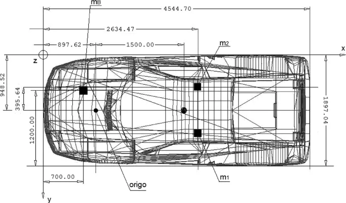
6.Define Body coordinate system?
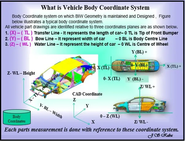
Coordinate system is a reference system Consisting of a set of point, Lines & surfaces used to define position of point in space either in 2 or 3 dimensions.
In general BCS is also called as car line or Body line
Car lines are the shown on the fixture, which virtually represent the same location in the BIW. All the car line on fixture display the coordinate at corner for reference. With these lines one can easily relate the, location in BIW.
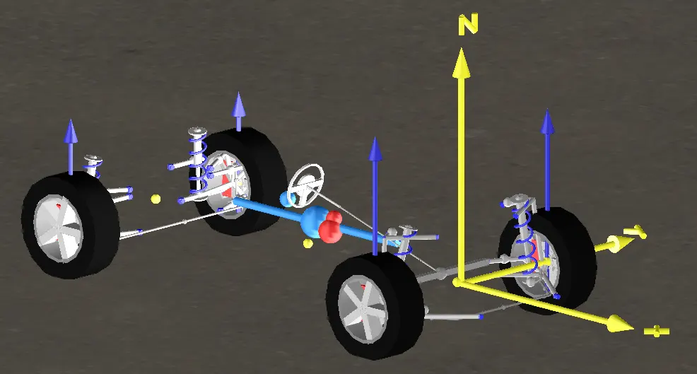
The coordinate system is orientation in terms of x, y and z relative to the vehicle, as in which axis goes in which direction normally defined as x, y, z in terms of the directions of the vehicle.
7.Elaborate Body plane system & its essentials.
It is basically a refrrence plane.these are used to define GD & T of all parts in automotive domain.
Bodylines dimensions are essential for below reason
- It defines exact position of each product in the vehicle w.r.t a fixed origin.
- It ensures flawless design for assembly.
- While designing lines, all the designs are carried out relative to the bodylines viz.fixtures, Turntables etc.
- It assist in easy location of different parts in the vehicle.
- It aims in creating a standardized system.
- It assist in quality checks.
Some examples which shows how we use body plane to define the exact position of part is shown below.