Week 2:- BiW Fixture Basics Challenge
1. What is the process of project execution activity?
1)RFQ received - RFQ stands for Request for Quotation. In this customer specifies his requirements,specifications etc. in form of documents or data. Also customer specifies its Technical offer, commercial offer, how the project will be executed & timeline to complete the project in it.
In BIW fixture design project begins. It starts with basic requirement or RFQ that we receive from customer. RFQ means request for quotation where in customer give his requirement specification etc. in form of some document or data to study or to work on information include such as technical offer, commercial offer, timeline of project Based on that we have processing to execute project.
2) 1st spec discussion & offer submission - In this the documents re;ated technical offer, commercial offer, project execution, Timeline required to complete the project are prepared. The time required to 3D design,Analysis of design, drawing & detailing, manufacturing, Assembly & commisioning etc. is considered. Then the cost of all the operation is also considered. By considering these kind of things the offer is prepared & submitted to the customer.
3) LOI/PO Receipt - The customer will study the offer submitted. He will also take quotations from others. The customer will study all the offers, compare offers & then select oner offer which suits best. The customer will generate po means Purchase order to start the work.Once we submitted offer customer will study the offer at the same time he will get offer from different supplier & vendor. He compares these technical offers & based on cost whichever suit best for his requirement. Then he will release LOI or PO with its terms & conditions as stated earlier.
4) Schedule preparation - After receiving the PO the project officially start. The timeline is fixed so there should be plan to beat the deadline & to complete the project. All the activities step by step are taken into account like po receipt, 1st meeting, design date analysis, 3D design preparation & simulation etc. the time required to finish the individual activity is calculated. By calculating all the steps the total time required is calculated. It should beat the timeline & if not then modifications is done in schedule to beat the timeline of the project. We should have some back up plan for this Because due to some reasons our tasks not complete on the fixed date or the next task is dependant on previous task.
5)BOM preparation - Bill of material is prepared for the project like the BO parts, grippers, cylinders, motors etc. which are required.
6) Design concept preparation - The customer gives data or the specifications for the design. Based on that data design process is start which fulfills all the customer requirements.
7) Customer approval - After designing the concept the approval of the customer is required. Customer checks the design fulfills the requirements or not according to the technical offer. If yes the customer gives approval for the design or customer will also ask for some addition or the changes in the design. By doing the necessary changes final approval is taken from the customer.
8) Detailing & DWG release - After the approval from customer DWG are released whic shows the detailed specifications of all the parts required. Like dimensions, Qty, Specifications etc.
9) Manufacturing BOP ordering - The BO parts like motors, cylinders, sensors, gripper etc. required for manufacturing are ordered as per the design specifications.
10) Mechanical/ Electrical assembly- Once the parts are received they goes for the prior Quality control checking. In this all the parts are checked as per the specification. After QC checking the Mechanical or electrical assemblis are prepared as per the design.
11)Quality inspection - After the assembly again the quality is checked. In this all the dimensions, positional accuracy, Coordinates are checked by using CMM machine.
12) Internal trial & testing & online trial - After the QC check internal trials are taken to check the fixture can do the operation or not for what it is designed. The simulation is done for this purpose at early stage. In this the fixture is checked for the clamping of the part, welding ,proper loading & unloading of the part etc.
After this online trial is taken in which all the operations done in automated mode by using electrical connections. The process sequence is checked as per the defined way in design in automated mode. Customer is also involved in online trial for taking the approval.
13) Packaging & dispatch - The assemblies are packed in proper manner. Because in trasportaion the fixture will be damaged hence it distorts the geometry of the fixture & also the functionality of the fixture. Hence the proper packaging is very important. Once the packaging is done the fixture is dispatched to the customer address.
14) Installation as per layout - layout is the space defined for the parts like fixture, robots etc, according to the functionality,application, process sequence etc. The layout is done at very initial level & according to that installation is done.
15) Trials & training at customer - Production trials are taken at customers end. In tecnical offer we have specified the quality benchmarks for the fixture, the capability of the fixture for production etc. The trials are taken to check the capability of the fixture. Once it is done then training is given to the operator, staff & engineer for the process sequence, how the fixture works, loading & unloading of the part etc.
16)Buy off meeting & Final handover - After production trial & training Customer check all the prescribed things in the offer are done or not. Sometime customer want some addition work also, so according to the rquirement all the points are closed & after that project finally handovered to the customer.
2.What are the types of joining processes?
Welding processes
The durability and performance of Lany largely dependent on the quality and the design of the Component. joints. Whole struchuse can not be made in one piece Two fundamental options for joining materials and Components :- Mechanical joining 8. Matallyssical joining
Resistance Welding & Il is welding technology widely used in manufacturing industry fore joining metal sheets and Compuses The weld is made by Conducting strong Cresent brough the metal Combination to heat up and finally melt the metals. al localized points Predetermined by the design of the electrodes. and/or the workpieces to be welded.
A force is always applied before, during and after the application of current to Confine the Contact area at line weld interface and in same applications to forge the workpiece.
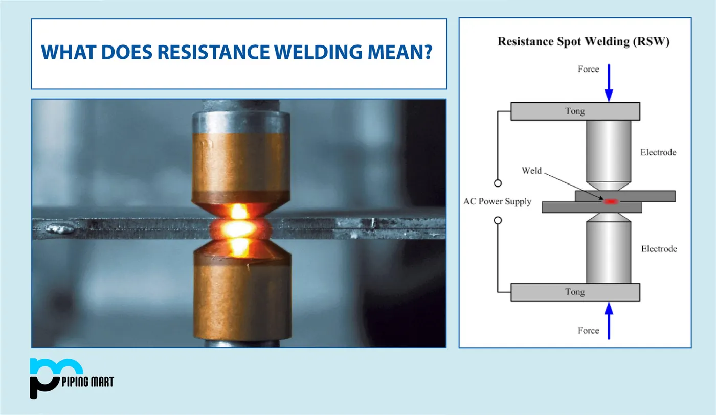
1.Resistance spot In welding - The process is used for joining sheet materials and used shaped Copper-chromium as zis coum allay dectsades to apply pressuse and Convey the electrical Cussent the ough the workpieces.Heat is developed mainly at the interface between two sheets eventually Causing the material being welded to melt framing molten paol the weld nuget. The molten pool is contamed by the pressure appliedby electrode tip and the sussounding Solid metal.
Advantage:
- shost weld time and hence high weld speed.
- Highly acceptable to automation and robotic techniques.
- Typical BEW contains 5000 welds.
- Strength and dusability of automobile largely depends on quality of RSW.
2. Resistance Welding
Resistance welding is a welding technology widely used in manufacturing industry for joining metal sheets and components.
The weld is made by conducting a strong current through the metal combination to heat up and finally melt the metals at localized point(s) predetermined by the design of the electrodes and/or the workpieces to be welded.
A force is always applied before, during and after the application of current to confine the contact area at the weld interfaces and, in some applications, to forge the workpieces.
Type of resistance welding
Resistance spot welding
Resistance seam welding
Resistance projection welding
a. Resistance Spot Welding
The process is used for joining sheet materials and uses shaped copper-chromium or zirconium alloy electrodes to apply pressure and convey the electrical current through the workpieces Heat is developed mainly at the interface between two sheets, eventually causing the material being welded to melt, forrying a molten pool, the weld nugget
The molten pool is contained by the pressure applied by the electrode tip and the surrounding solid metal
Advantage:
- Short werd time and hence high weld speed Highly adaptable to automation and robotic techniques
- Typal BIW contains 5000 welds
- Seength and durability of automobile largely depends on quality of RSW.
b. Resistance Projection Welding
Projection welding is a resistance welding process for joining metal components or sheets with embossments by directly applying opposing forces with electrodes specially designed to fit the shapes of the workpieces The current and the heat generation are localized by the shape of the workpieces either with their natural shape or with specially designed projection Large deformation or collapse will occur in the projection Part of the workpieces implying high
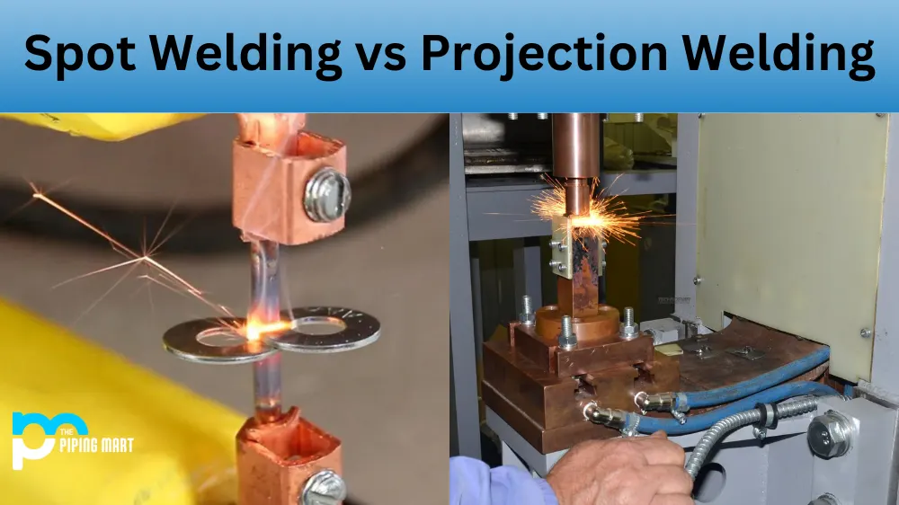
Application Used for hanical fixing of autobody eg. Weld nuts.
c. Resistance Seam Welding
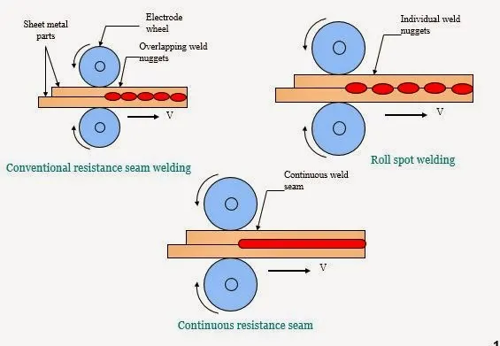
Seam welding is a resistance welding process for joining metal sheets in continuous, often leak tight, seam joints by directly applying opposing forces with electrodes consisting of rotary wheels.
The current and the heat generation are localized by the peripheral shapes of the electrode wheels.
Application
Seam welding is mostly applied in manufacturing of containers, radiators and heat exchangers etc.
3.Arc welding
The processes involves either consumable or a non consumable electrode (rod or wire).
An arc produced between tip of the electrode and work piece to be welded, by use of an AC or a DC power supply.
Type of arc welding
- Manual metal arc welding
- Gas-shielded metal arc welding (Metal inert gas (MIG) welding)
- Gas-shielded tungsten arc welding (Tungsten inert gas (TIG) welding)
- Submerged arc welding
- Plasma arc welding
a. Manual metal Arc welding
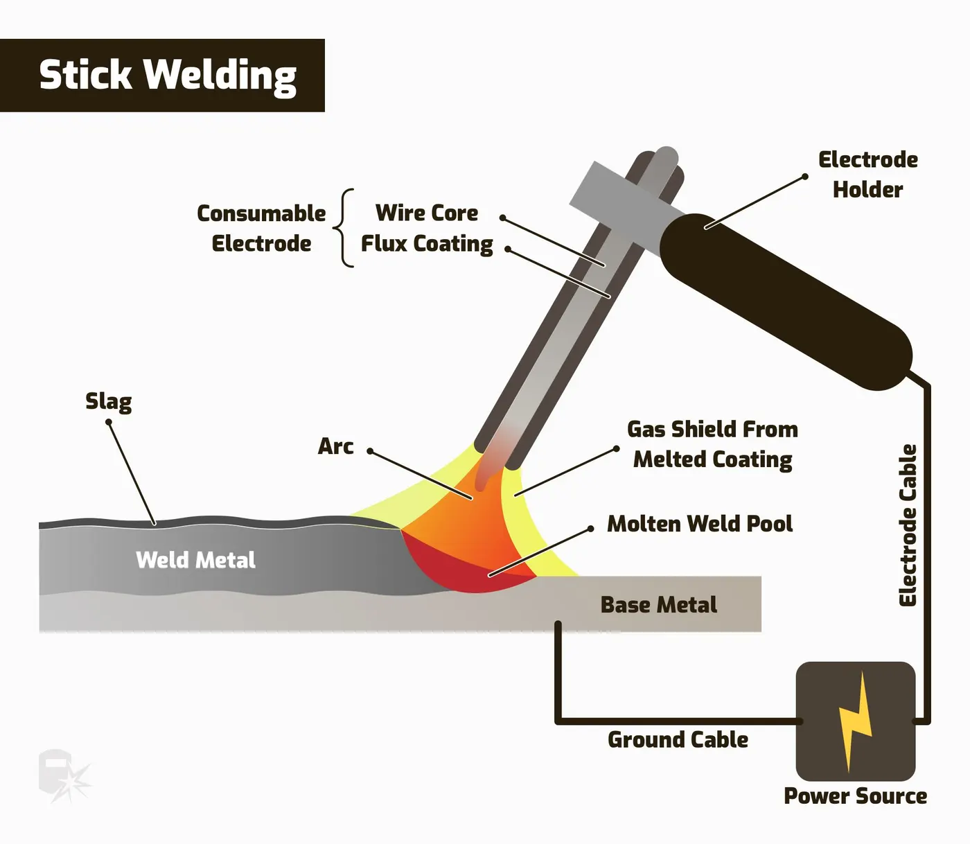
Manual metal arc welding (MMA or MMAW) also known as Shielded metal arc welding(SMAW), or informally as stick welding.
Stick welding is a process where the arc is struck between the metal rod (electrode flux coated) and the work piece. both the rod and work piece surface melt to create a weld.
b. Gas-shielded metal arc welding
(Metal inert gas (MIG) welding) Metal Inert Gas (MIG) Welding is an arc welding technique in which a consumable electrode is used to weld two or more work pieces.
- MIG Welding makes use of the following components:
- Consumable Electrode Inert Gas Supply
- Welding Head
- AC or DC Power Supply
c. Gas-shielded tungsten arc welding (Tungsten inert gas (TIG) welding)
Tungsten Inert Gas Welding (TIG Welding), also known as Gas Tungsten Arc Welding (GTAW), is an arc welding method that uses a non-consumable tungsten electrode to weld two or more workpieces. It is very much similar to Metal Inert Gas (MIG)
The following components are necessary to do Welding.
- Tungsten Inert Gas Welding:
- Power supply
- Non-Consumable tungsten electrode
- Inert Gas Supply
- Filler rod (depend on the nature of work piece)
- Welding Head
Mechanical fastening
The joining of material combinations which cannot be easily welded such as pre-painted steels or very dissimilar metals
Ex: Al application in auto body make use of mechanical fastening techniques to overcome the poor inherent weld ability of Al
The joining of materials in applications where high fatigue life is critical compared to statico strength
The joining of materials where a long tool life is of relative importance Screws and bolts
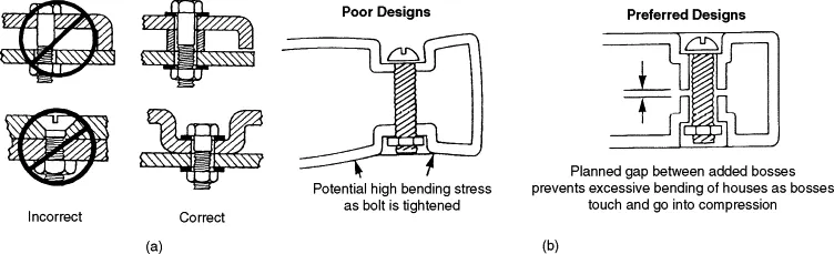
Self piercing riveting
Self-piercing riveting is a high-speed mechanical fastening process for point joining sheet material, typically steels and aluminium alloys. It is a single-step technique, generally using a semi-tubular rivet to clinch the sheets in a mechanical joint There is also a process variant which utilises solid rivets.
As the name suggests, pre-drilled holes are not required, allowing the joint to be made rapidly in one operation. The ocess cycle is shown in cross-section below.
Hemming process
Hemming and seaming are two similar metal working processes in which a sheet metal edge is rolled over onto itself.
Hemming is the process in which the edge is rolled flush to itself, while a seam joins the edges of two materials
Adhesive Bonding
Adhesive bonding is used to fasten two surfaces together, usually producing a smooth bond.
This joining technique involves glues, epoxies, or various plastic agents that bond my evaporation of a solvent or by curing a bonding agent with heat, pressure or fine.
3. What is Resistance Welding & its application in the automotive sector?
Automobile application of arc welding -
- Arc welding is used to weld the chasis parts in automotive industry.
- Arc welding wire for automotive steel sheets
Solid wires suitable for robot welding that generate compara-tively small amounts of slag and fume are chosen for welding of au-tomotive parts.
- Arc welding is used to weld the body parts in Automotive industry-
Low heat input welding of thin steel sheetsPrevention of burn-through due to excessive heat input is im-portant in the welding of car body parts of thin sheets. For this rea-son, thin welding wire with a diameter of 0.9 mm, which enables stable welding at low currents, and low-heat-input welding power sources
- TIG welding is used to join thin stainless steel parts & various piping parts inautomobile industry.
- MIG welding is used for the repairing work in automobile industry wheather they are small, big, light or heavy.
4. What is fusion welding & types of fusion welding with its application in the automotive sector?
In fusion-welding processes, heat is applied to melt the base metals. In many fusion welding processes, a filler metal is added to the molten pool during welding to facilitate the process and provide strength to the welded joint. When no filler metal is used, that fusion welding operation is referred to as autogenously weld. Fusion welding is unique, however, because of its ability to “fuse” the respective objects. Assuming the objects are made of the same or similar materials, the heat produced by a welding rig will melt their surfaces, thereby allowing the objects to fuse together. Fusions welding are categorized according to source of heat for example electric arc, electric resistance, gas, high energy.
1) Arc Welding:
The most popular type of fusion welding is arc welding. The process involves either consumable or non consumable electrode rod or wire. Arc welding lives up to its namesake by relying on an electric arc to join two or more objects. An arc produced between tip of electrode & workpiece to be welded by an AC or a DC power supply. With electric arcs measuring up to 6,000 degrees Fahrenheit, this fusion welding process is highly capable of melting even toughest metals. Furthermore, arc welding can be performed underwater, making it an ideal solution for offshore welding projects. This process can be categorised into two different types; consumable and non-consumable electrode methods.
Type of arc welding
- Manual metal arc welding
- Gas-shielded metal arc welding (Metal inert gas (MIG) welding)
- Gas-shielded tungsten arc welding (Tungsten inert gas (TIG) welding)
- Submerged arc welding
- Plasma arc welding
a. Manual metal Arc welding
Manual metal arc welding (MMA or MMAW) also known as Shielded metal arc welding(SMAW), or informally as stick welding.
Stick welding is a process where the arc is struck between the metal rod (electrode flux coated) and the work piece. both the rod and work piece surface melt to create a weld.
b. Gas-shielded metal arc welding
(Metal inert gas (MIG) welding) Metal Inert Gas (MIG) Welding is an arc welding technique in which a consumable electrode is used to weld two or more work pieces.
- MIG Welding makes use of the following components:
- Consumable Electrode Inert Gas Supply
- Welding Head
- AC or DC Power Supply
c. Gas-shielded tungsten arc welding (Tungsten inert gas (TIG) welding)
Tungsten Inert Gas Welding (TIG Welding), also known as Gas Tungsten Arc Welding (GTAW), is an arc welding method that uses a non-consumable tungsten electrode to weld two or more workpieces. It is very much similar to Metal Inert Gas (MIG)
The following components are necessary to do Welding.
- Tungsten Inert Gas Welding:
- Power supply
- Non-Consumable tungsten electrode
- Inert Gas Supply
- Filler rod (depend on the nature of work piece)
- Welding Head
5. What is the 3-2-1 principle?
FIXTURE DESIGN
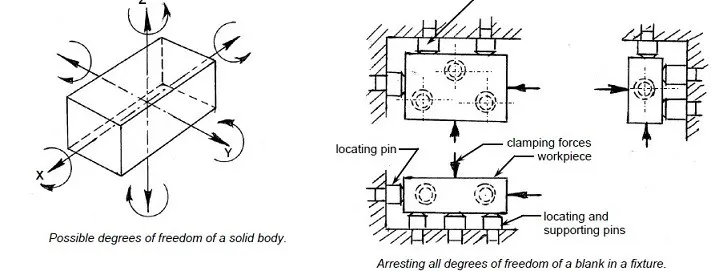
Fixtures must correctly locate a work piece in a given orientation with respect to a cutting tool or measuring device, or with respect to another component. Locating and clamping are the critical functions of any work holding fixture.
A work piece free in space can move in an infinite number of directions. For analysis, this motion can be broken down into twelve directional movements, or "degrees of freedom". All twelve degrees of freedom must be restricted to ensure proper referencing of a work piece.
3-2-1 PRINCIPLE
The best and most cost effective method of part location is referred to as the 3-2-1 method
(3.) Minimum: three locator blocks to establish part plane. Three locators, or supports, are placed under the work piece. The three locators are usually positioned on the primary locating surface. This restricts one axial movement downward, and 4 radial movements. Together, the three locators restrict five degrees of freedom.
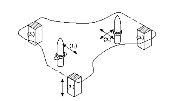
(2) Round locating pin in a round hole that defines location in four directions (4-way) perpendicular to the plane Previously established. This restricts four axial movement.
1) Round locating pin in a slot that defines two of the directions of the othe pin (2-way) This restricts two axial movements.
In this, (3) means restricting three degree of freedom as translation motion in z axis i.e. upward & downward, two rotational motion about x & y axis.
Secondly, (2) means restricting two degrees of freedom. Translation motion in x (i.e. +ve or –ve) & y direction i.e. (+ve or –ve)
& (1) means restricting one degrees of freedom i.e. rotational motion about z axis clockwise or anticlockwise. So car panel or body cannot move in any direction with or without application of external force so properly fixed in fixture. This is basic concept of designing fixture.
Conclusion:
The jig and fixture are tools used for holding the work piece in a correct location for mass production. Various types of fixtures (like drilling fixtures and welding fixtures) are used in industry. The 3-2-1 method is the fundamental principle for all types of fixture design.
6.Define Body coordinate system?
Body Coordinate system in BIW:
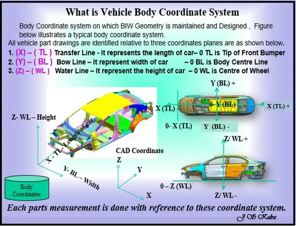
The body coordinate system has been widely used in the automotive industry for drawing of body parts product and process design.
A coordinate system is a reference system consisting of a set of points lines and surfaces used to define the positions of points in space in either two or three dimensions.
In general BCS is also called as car line and Body line.
X-Longitudinal direction [(Fore & After-F/A) or (Front O Line FOL)]
Y-Transverse direction [(Cross car- C/C) or (center O Line COL )]
Z-Vertical direction [(Up & Down-U/D) or (Bottom O Line BOL)]
The origin of the body coordinate system(OX) is defined at the front center of a vehicle, it indicates a length of car and the coordinate system of (OZ) car is below its underbody indicates height of the car and the coordinate system (OY) its starting point is center of car body indicates width of car.
Body planes are the reference planes in an automotive car. These planes are used to define GD&T of all car parts in a automotive domain.
Body planes are 3 mutually perpendicular imaginary planes. These are generally considered be present at the Driver position or sometimes at the engine location or at the front end of e car depending on the customer
The Measurements from the body planes to the parts are called as bodyline dimensions
These body planes are called as
FOL Front "O" Line
COL Centre "O" Line
BOL Body "O" Line
The Measurement along FOL or X axis is called as F/A Front Aft
The Measurement along COL or Y axis is called as C/C Cross Car
The Measurement along BOL or Z axis is called as U/DUP Down
7. Elaborate Body plane system & its essentials.
Bodyline dimensions are essential for the reasons stated below,It defines the exact position of each product in the vehicle w.r.t. a fixed origin.It ensures flawless design for assembly.While designing lines, all the designs are carried out relative to the bodyline, viz, fixture, turn table etc.It assists in easy location of different parts in a vehicle.It aims in creating a standardized system.It assists in quality checks.
These are basic essential thing that body line dimension would help in BIW. It could help in designing lines like welding lines, assembly lines or car body through fixture & turntable etc. This help in designing every tools. Particular assembly or parts are designed w.r.t body lines or an axis system or car line also helps in quality while doing CMM of that system. CMM is basically done with the help of coordinate. It has relate particular fixture with that car part, because that dimension, coordinates of hole & pin should match so it will help in quality check also. We just give coordinates that belong to that hole both coordinate should match. With this matching means quality is approved.