Week 2:- BiW Fixture Basics Challenge
Q 1. What is the process of project execution activity?
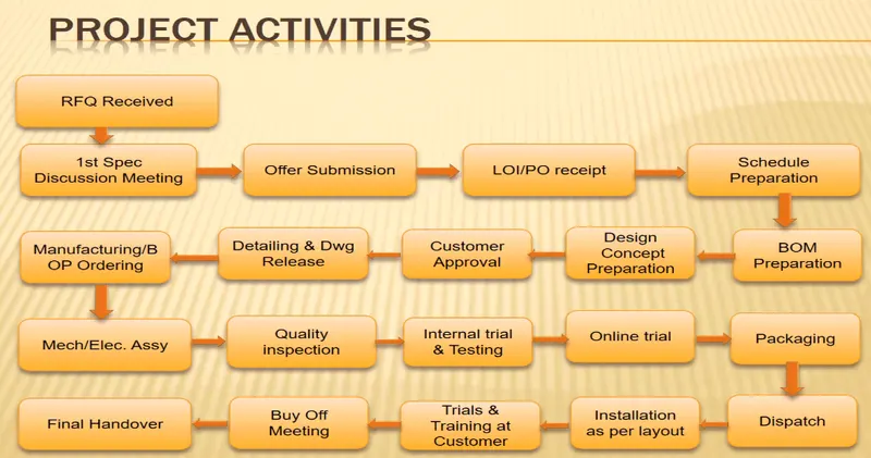
Answer: Implementing the already-designed strategy is the aim of project execution. It requires completing every task that was outlined during the earlier project cycle procedures. The operations are completed in line with the defined plans, sequence, and processes to satisfy the project's needs. project. The achievement of the desired results is the aim of project execution.
Any project is consisting of foloowing steps/activities which make sure the feasibility of the project.
The common process followed in executing these activities are as
1. Verify that the management plan is being followed as the activities are being conducted.
2. Create the team, advance it, and keep it going throughout the project's life cycle.
3. Utilizing the project plan, produce a deliverable, then evaluate the procedures and plans necessary to produce the final product.
4. Make sure the project team is managed well to maximise their performance and resolve any difficulties as soon as they arise.
5. Make sure the channels of communication are open at all times so that information can be received and responses can be given promptly.
6. Ensure that a project is executed with perfection to ensure that quality is reached.
Q 2. What are the types of joining processes?
Answer: Following are the types of joining processes
- Resistance Welding (Spot welding, seam welding, projection welding)
- Arc welding (Manual metal arc welding, Metal inert gas (MIG) welding, Tungsten inert gas(TIG welding), Submerged arc welding, Plasm arc welding)
- Gas Welding
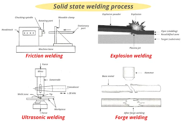
- Friction Welding
- Explosion Welding
- Ultrasonic Welding
- Forge Welding
- Pressure Welding
- Friction stir welding
- Soldering
- Brazing
- Mechanical Fastening
- Self-piercing riveting
- Hemming process
- Adhesive Bonding
Q 3. What is Resistance Welding & its application in the automotive sector?
Answer: Resistance welding is the process of combining metals by exerting pressure and continuously running current through the metal portion that needs to be welded. The main benefit of resistance welding is that no additional materials are required to form the bond, which makes it a very economical procedure.
Resistance welding comes in a number of types (such as spot and seam, projection, flash, and upset welding), which vary mainly in the kinds of weld electrodes that are used to apply pressure and conduct electricity. Water is pumped through cavities into the electrodes and other conductive equipment of the resistance welding machine to cool them. Electrodes are commonly made of copper-based alloys because of their greater conductivity.
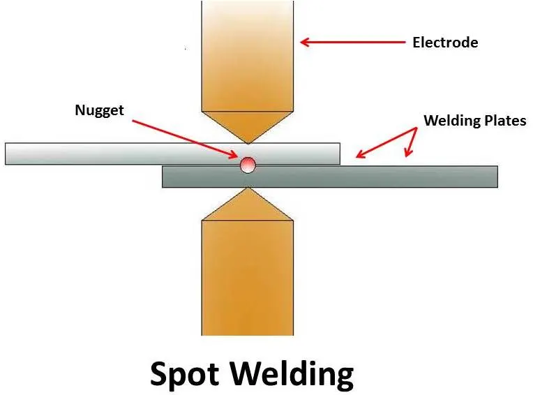
a. Resistance Spot Welding:
It is widely used in BIW manufacturing. Almost 40% of the joining processes is carried out by the resistance spot welding process.
Resistance Spot Welding produces welds using heat produced by resistance to the flow of welding current between the faying surfaces and force to push the workpieces together, both of which are applied over a predetermined time period. Resistance Spot Welding concentrates the welding current at the desired weld site and exerts force on the workpieces by utilising the face geometries of the welding electrodes. Once there is enough resistance created, the components come together, settle, and a weld nugget is created.
b. Reistance Seam Welding:
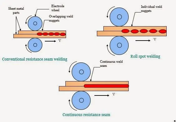
A variation of resistance spot welding that uses wheel-shaped electrodes to apply force and welding current to the component pieces is resistance seam welding. The difference is that while welding current is supplied, the workpiece rolls between the wheel-shaped electrodes. The welds produced may overlap, form a full welded seam, or may just be single spot welds at predetermined intervals, depending on the specific weld current and weld duration settings.
c. Resistance Projection Welding:
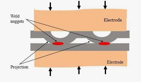
Projection welding uses force to press the workpieces together over a predetermined length of time in addition to heat produced by resistance to the flow of welding current. By utilising projections, embossments, or intersections, all of which concentrate heat generation at the point of contact, projection welding localises the welds at preset points. The projections collapse and form the weld nugget after the weld current produces enough resistance at the site of contact.
When joining items together using welding, solid projections are frequently employed. When attaching sheets or plates of material, embossments are frequently utilised. Cross-wire welding is an illustration of projection welding employing material intersections. In this instance, resistance and heat creation are localised to the intersection of the wires. The wires came together and formed a weld nugget as a result.
Q 4. What is fusion welding & types of fusion welding with its application in the automotive sector?
Answer: By heating two or more materials to their melting points, fusion welding employs heat to combine or fuse the materials together. The use of a filler material may or may not be necessary during the procedure. With the exception of resistance welding, where significant contact pressure is necessary during welding for good joining, fusion welding procedures do not require external application of pressure.
Fusion welding processes can be grouped according to the source of the heat, for example, electric arc, gas, electrical resistance and high energy. The Fusion welding is used in the manufacture of many everyday items including airplanes, cars, and structures.
Types of Fusion Welding are explained below:
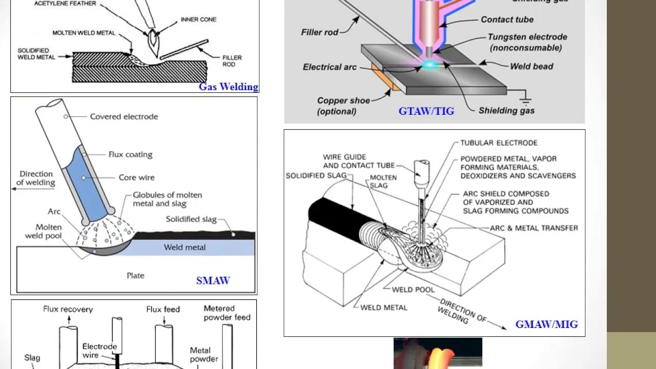
Manual Metal Arc Welding: Shielded metal arc welding, also known as manual metal arc welding, flux shielded arc welding or informally as stick welding, is a manual arc welding process that uses a consumable electrode covered with a flux to lay the weld. Suitable for all positions of welding on ferrous and non-ferrous materials.
MIG Welding: MIG sometimes referred to as Gas Metal Arc Welding, is type of metal welding (GMAW). In this method, an electric arc forms between a consumable electrode that can be replaced and the workpiece, causing them to melt and fuse together. Requires a shielding gas to prevent oxidation in the case of MIG welding or airborne pollutants from damaging the weld.
TIG Welding:
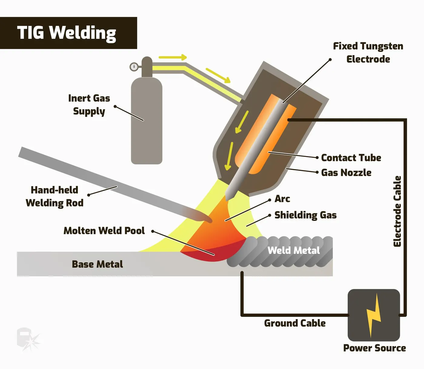
The arc between the electrode and the base plate is produced by this arc method using a non-consumable tungsten electrode. To guard against oxidation or other ambient pollution, an inert shielding gas is utilised. On thin parts, this procedure can be employed automatically; however, for thicker parts, a wire, rod, or consumable must be introduced.
Submerged Arc Welding:
This frequently-used arc welding process uses a continuously-fed consumable electrode and a blanket of fusible flux which becomes conductive when molten and provides a current path between the workpiece and the electrode. The flux also prevents spatter and sparks while suppressing ultraviolet radiation and fumes.
The method of submerged arc welding is typically automated or mechanical and is said to be highly productive. A single wire is used in the process's most basic implementation.
The size of the available power source typically dictates the maximum wire diameter that can be used when choosing the right wire diameter for a welded junction. Although 1,000 amps is the typical power supply for this operation, lower power sources may be employed. Direct current with the electrode positive (DC+) will operate in the 300 to 900 amp range through a 3/32-in.-diameter wire through a 5/32-in.-diameter wire.
Plasma Arc Welding:
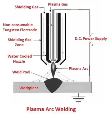
An electric arc that forms between an electrode and the torch nozzle is used in this technique. A "plasma" is created when the electric arc ionises the gas in the chamber, which is typically argon. The arc is then compressed and directed to the workpiece via a fine bore copper nozzle, allowing the plasma arc to be isolated from the shielding gas (which is usually made from a mixture of argon and hydrogen).
Q 5. What is the 3-2-1 principle?
Answer: Locating the component to be machined, punched, bent, or stamped in relation to the work platform is a fundamental concern in metalworking (fixture). For instance, a CNC machine tool begins its operation at a certain location in relation to the fixture and moves forward from there. Therefore, the precision with which an item is positioned in the fixture has a significant impact on the accuracy with which it is machined.
It is essential to accurately locate every component inserted into the fixture, not just one. The dimensional tolerance that needs to be supplied to the completed parts increases with any difference in the part's placement on the fixture.
Additionally, not only do dimensional tolerances and surface finishes depend on how the item is supported and held in the fixture, but they also do. This is accurate since poor clamping or supporting can cause a part's deformation to be either temporary or permanent. To ensure repeatability from part to part, supporting and clamping techniques must be taken into account in addition to the method of location.
When mounting an item in a fixture for machining, we want to accomplish two things:
1. Exact the part's location at the specified coordinates.
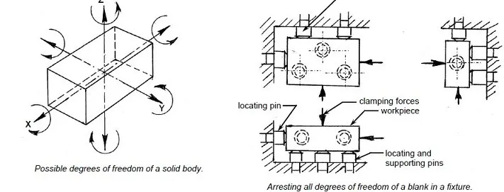
2. Limit each of the six degrees of freedom to prevent the part from moving.
The 3-2-1 principle, so named because it involves three steps that use three, then two, then one fixed points of known locations, is a widely used technique for achieving these two goals. It is also referred to as the "six point approach" because that equals six fixed points.
Three mutually perpendicular planes, or datum planes, are introduced, one at each of the three steps of the 3-2-1 technique. These three planes specify the workpiece's location, and they totally restrain the part along with opposing clamping forces.
The 3-2-1 method is a work-holding principle where three pins are placed either on the XY, YZ, or ZX axes of the first principle plane. Additionally, there are two pins on the second plane that are parallel to the first, and one pin on the plane that is perpendicular to both the first and second planes at the same time. The goal is to limit the workpiece's movement along each of the three axes.
Q 6. Define Body coordinate system?
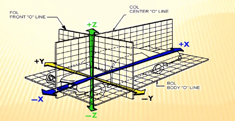
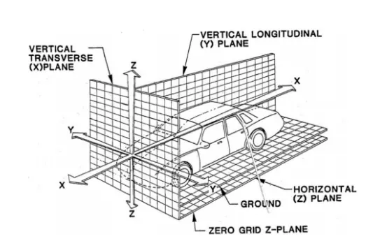
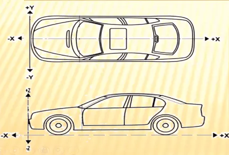
Answer: Body Co-ordinate System (BCS) is a reference system used to define the position of a point in space in either two or three dimensions. It consists of a collection of points, lines, and surfaces. It is frequently used in the automotive sectors for designing products and processes as well as drawing parts. In the auto industry, it is also referred to as body line and car line. The front centre of an automobile is where the BCS OX is defined, and this location denotes the length of the car. Underneath the car's underbody, the coordinate system OZ shows the vehicle's height, while the coordinate system OY shows its breadth.
Q 7. Elaborate Body plane system & its essentials.
Answer: The reference planes used to establish the GD&T of all car elements and components are called body planes in the automotive car depicted in the above figure. The grids in the above graphic demonstrate how these planes are mutually perpendicular to one another. Bodyline dimensions are the measurements taken from body planes to components.
The body coordinate system has been widely used in the automotive industry for drawing of body parts. product and process design. A coordinate system is a reference system consisting of a set of points, lines and surfaces, used to define the positions of points in space in either two or three dimensions. In general BCS is also called as car line and Body line.
The origin of the body coordinate system (OX) is defined at the front center of a vehicle, it indicates a length of car and the coordinate system (OZ) is below its underbody indicates height of car, and the coordinate system (OY) its starting point is the center of car body indicates width of car.
Importance:
- It defines the exact position of each product in the vehicle w.r.t. a fixed origin.
- It ensures faultless design for assembly.
- All the design are carried out relative to the bodyline.
- It aims are to create a standardized system.
- Due to these all its helps in proper quality check.