Week 2:- BiW Fixture Basics Challenge
1. Project execution activity:
Project activities are those basically are being processed or being practiced in general project of BIW begins. Project activities are task from start to end of project. There are various step involved in project. Below fig. show flow chart of project activities.
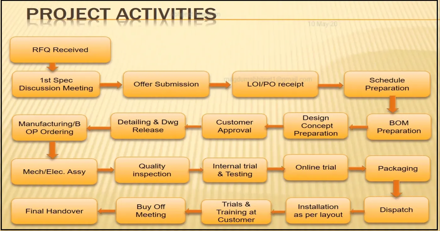
RFQ:
In BIW fixture design project begins. It starts with basic requirement or RFQ that we receive from customer.
1st specification discussion meeting & offer submission:
In this the documents related technical offer, commercial offer, project execution, timeline required to complete the project are prepared.
PO/LOI: Once we submitted offer customer will study the offer at the same time he will get offer from different supplier & vendor. He compares these technical offers & based on cost whichever suit best for his requirement. Then he will release LOI or PO with its terms & conditions as stated earlier.
Schedule Preparation: In project each activity depends on previous activity. So if previous activity has not completed on time it will cause delay in next activity date is fixed so that it will move further.
BOM Preparation: BOM preparation is listing down of part list which includes bought out parts, vendor parts, and consumable items with qty.
Design concept preparation: Further step is to design a concept.
Customer approval: As design concept ready then it is send to customer for its approval. It is also known as design approval process (DAP).
Detailing & Dwg. release: In detailing all assemblies broken down into its child parts. Parts of assembly are segregated into std. as well as manufactured.
Manufacturing & B/O ordering: Manufacturing department will receive all dwg to start manufacturing of items like mylar, blade, riser, base frame.
Mechanical & electrical assembly: After qc check, parts are available for assembly. A station is integration of all mechanical as well as electrical assembly.
Internal trial & testing: After approval of qc team, Internal trials & testing started.
Online training: After successful of trial next step is online training. In online training has two mode manual & automated.
Packaging: After trial get successful, customer give approval to dispatch system. To dispatch whole system needs to disassemble station wise & pack properly.
Dispatch: All material transported at customer site through trucks, container, and ships or by air.
Installations: All system is assembled & installed at customer end as per layout approved initially in DAP.
Trial & training at customer end: Once installation is done trial start at customer end.
Buy off meeting: Once training is completed there is buy off meeting between customer & project team with discussion on if there other things need to be incorporated, anything missing that described in LOI/PO or offer submission.
Final handover: Once all points raised by customer will be closed then all will go for final handover.
2. Types of joining processes:
The durability and performance of any structure is largely depends on quality & design of components joints. Whole structure can’t be made in one piece. Two fundamental option for joining material & components.
- Metallurgical joining
- Mechanical joining.
Metallurgical joining: In welding two or more parts are heated & melted or forced together, causing the joined parts to function as one. In some welding method filler material is added to make the merging of materials easier. Examples of metallurgical joining are:
Welding
Brazing
Soldering
Adhesive Bonding
Diffusion Bonding etc.
Mechanical joining:
Mechanical joining is a process for joining parts through clamping or fastening using screws, bolts or rivets. Advantages of mechanical joining include versatility, ease of use, and the option to dismantle the product in cases where regular maintenance requires it. The ability to join dissimilar materials is another benefit. Examples of mechanical joinings are
Mechanical fastening
Self piercing riveting
Hemming & seaming process
3). Resistance welding & its application in automotive sector:
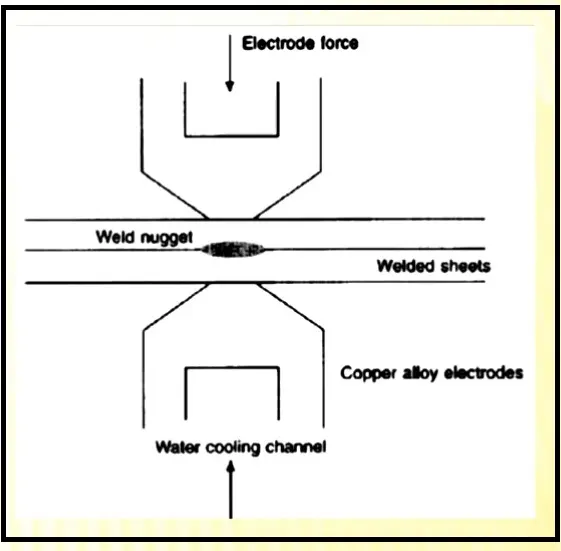
- Resistance welding is technology widely used in manufacturing industry for joining sheet metal & component.
- The weld is made by conducting a strong current through metal combination to heat up & finally melts metal at localized points predetermined by the design of electrodes and or the work piece to be welded.
- A force is always applied before, during & after application of current to confine the contact area at weld interface & in some workpiece to forge the wokpiece. Below fig. shows resistance welding technique.
Types of resistance welding:
- Resistance spot welding
- Resistance seam welding
- Resistance projection welding.
1). Resistance spot welding-
Resistance spot welding widely used in BIW joining processes. The process is used for joining sheet materials & uses shaped copper chromium or zirconium alloy electrode to apply pressure & convey electrical current through the workpiece. Heat is developed mainly at interface between two sheet, eventually causing material being welded to melt, forming a molten pool & weld nugget.
Following are advantages of resistance spot welding.
- Short weld time & hence high weld speed
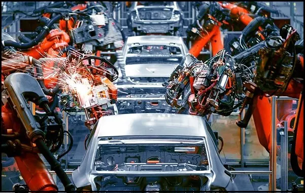
- Highly adaptable to automation & robotic technique. Below figure show robot used in automotive industry for spot welding. Typical BIW contains 500 weld. RSW is automated and used in the form of robotic spot welding in automotive industries to weld the sheet metals to form car body. Below figure illustrate typical application of spot welding using robots.
2).Resistance seam welding:
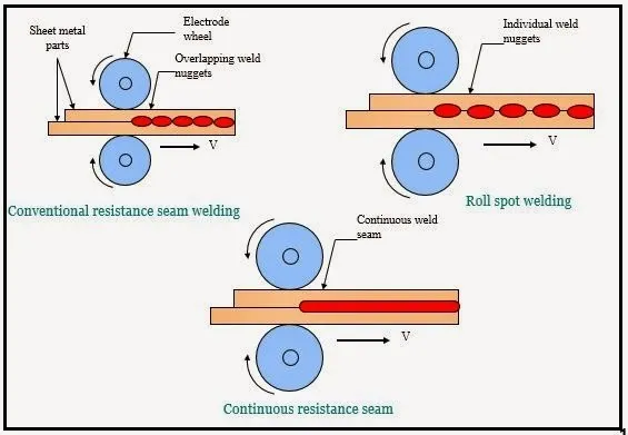
Resistance seam welding is welding process for joining metal sheets in continuous, often leak tight, and seam joints by directly applying opposing forces with electrode consisting of rotary wheel. It differs from flash welding in that flash welding typically welds the entire joint at once and seam welding forms the weld progressively, starting at one end. The current & the heat generation are localized by peripheral shapes of electrode wheel Seam welding is mostly applied in manufacturing of containers radiators & heat exchangers etc.
3).Resistance projection welding:
Projection welding is process for joining metal components or sheets with embossment by directly applying opposing forces with electrode specially designed to fit the shape of workpieces.
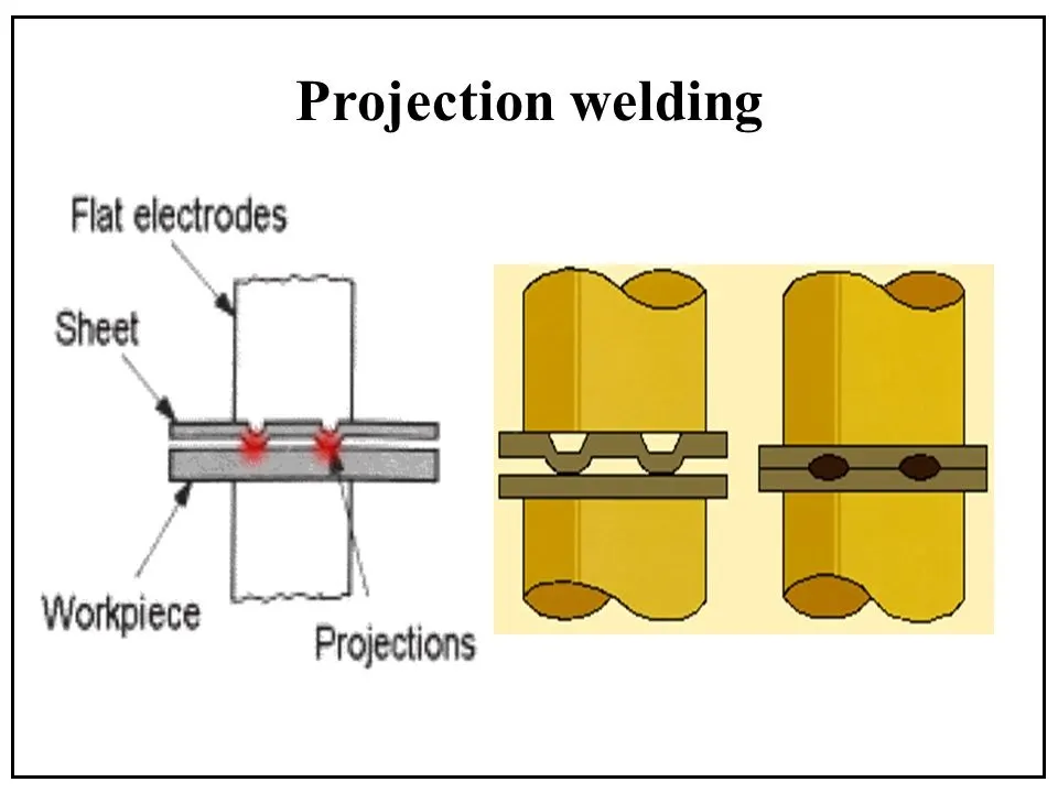
It used for mechanical fixing of auto body structure e.g. to weld nut. In BIW body there will be many welded nut, stud, bolt that need to be welded on sheet. It will use further stages for fastening process.
4. Fusion welding & types of fusion welding with its application in automotive sector:
In fusion-welding processes, heat is applied to melt the base metals. In many fusion welding processes, a filler metal is added to the molten pool during welding to facilitate the process and provide strength to the welded joint.
Types of fusion welding:
Arc welding: The most popular type of fusion welding is arc welding. The process involves either consumable or non consumable electrode rod or wire. Arc welding lives up to its namesake by relying on an electric arc to join two or more objects. This process can be categorised into two different types; consumable and non-consumable electrode methods.
a).Manual metal arc welding or Shielded Metal Arc Welding (SMAW):
Also known as manual metal arc welding (MMA or MMAW), flux shielded arc welding or stick welding is a process where the arc is struck between the metal rod (electrode flux coated) and the work piece, both the rod and work piece surface melt to form a weld pool.
b).Gas shielded metal arc welding or metal inert gas welding or MIG:
Metal inert gas (MIG) is an arc welding technique in which consumable electrode is used to weld two or more workpieces. MIG welding are most common arc welding processes, in which arc forms between consumable wire electrode & workpiece leading them to melt & join.
c) Gas- shielded tungsten arc welding or TIG:
Tungsten inert gas welding, also known as gas tungsten arc welding (GTAW), is an arc welding method that uses a non consumable tungsten electrode to weld two or more workpieces.
d). Plasma arc welding:
The Plasma arc welding (PAW) is similar to GTAW or gas tungsten welding. In this kind of welding process, the arc will generate among work part as well as the tungsten electrode.
e). Submerged Arc Welding:
The Submerged arc welding (SAW) can be extensively utilized within an automatic welding method. In this kind of welding process, an electrode is completely submerged by the granular coating of flux, and this flux can be an electric conductor which will not oppose the electric supply.
Automotive application of arc welding:
- Arc welding is used to weld the chassis parts in automotive industry.
- Arc welding is used to weld body parts in automotive industry. Low heat input welding of thin steel sheets prevention of burn through due to excessive heat input is important in the welding of car body parts of thin sheets.
- TIG welding is used to join thin stainless steel parts & various piping parts in automobile industry.
- Rebuilding: MIG welding is used for repairing work in automobile industry.
5). 3-2-1 principle:
Degrees of freedom: The degree of freedom defines as the capability of a body to move. Consider a rectangular box, in space the box is capable of moving in twelve different directions (six rotational & six axial).
6 translational degrees of freedom: +X, -X, +Y, -Y, +Z, -Z.
And 6 rotational degrees of freedom:
- Clockwise around X axis (CROT-X).
- Anticlockwise around X axis (ACROT-X).
- Clockwise around Y axis (CROT-Y).
- Anticlockwise around Y axis (ACROT-Y).
- Clockwise around Z axis (CROT-Z).
- Anticlockwise around Z axis (ACROT-Z).
Each direction of movement is counted as one degree of freedom. i.e. a body in space has twelve degree of freedom.
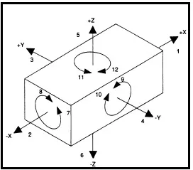
Above figure shows a body in space & its possible direction of movement. The body can move two directions along the each axis of three mutually perpendicular axes; also can rotate about this axis either clockwise or anticlockwise. There are twelve degree of freedom for body in space.
Locating: the positional & dimensional relationship between workpiece & cutting tool.
Locator: the device to establish & maintain the position of the workpiece in work holders such as jig & fixture to ensure repeatability of work holder.
The best & most effective method of part location is 3-2-1 principle. Holding fixtures used in assembly operations often follow a 3-2-1 locating scheme to position parts. Under this scheme, three locators position a part in a primary plane or direction (e.g., high/low). Two locators then position the part in a secondary direction (e.g., in/out), leaving one locator for the tertiary direction (e.g., fore/aft). This approach fixes the part in 3-dimensional space and satisfies the six degrees of freedom constraint.
(3) minimum plane: Three locator blocks to establish part plane. Three locator or supports are placed under the workpiece. Three locators are usually positioned on primary locating surface. This restricts one axial movement downward, & 4 radial movements. Together, the three locators restrict five degrees of freedom.
(2) Round locating pin in a round hole that defines location in four directions (4 ways) perpendicular to the plane previously established. This restricts four axial movements.
(1) Round locating pin in slot that defines two of the other pin (2-way). This restricts two axial movements.
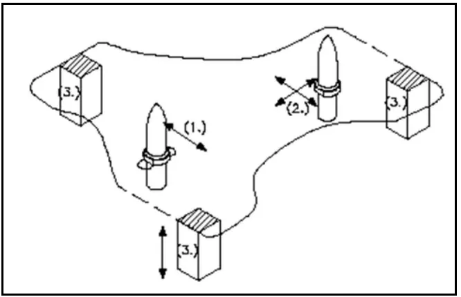
The better way of understanding of 3-2-1 principle that considers 12 degrees as of 6 degrees of freedom. It include clockwise & anticlockwise as one rotation. Movement in +ve & -ve direction as one translation motion. So we have three translation motion in x, y, z axis & three rotational motion about x, y, z axis
In this, (3) means restricting three degree of freedom as translation motion in z axis i.e. upward & downward, two rotational motion about x & y axis.
Secondly, (2) means restricting two degrees of freedom. Translation motion in x (i.e. +ve or –ve)
& y direction i.e. (+ve or –ve)
& (1) means restricting one degrees of freedom i.e. rotational motion about z axis clockwise or anticlockwise. So car panel or body cannot move in any direction with or without application of external force so properly fixed in fixture. This is basic concept of designing fixture.
6. BODY COORDINATE SYSTEM:
The body coordinate system has been widely used in the automotive industry for drawing of body parts, product & process design. A coordinate system is a reference system consisting of a set of points, lines & surfaces, used to define the positions of points in space in either two or three dimensions. In general BCS is also called as car line & body line.
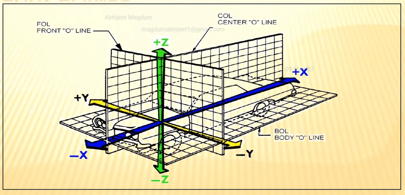
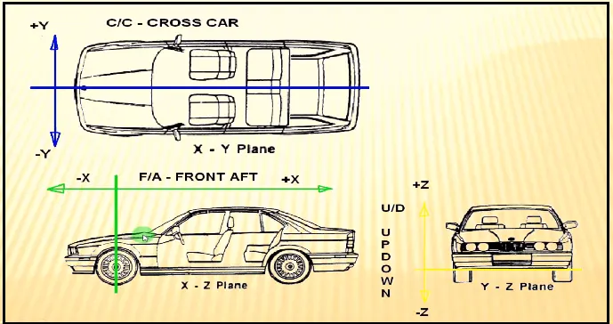
These datum schemes provide a reference system for all part surfaces and features using body coordinates. Figure below illustrates a typical body coordinate system. This system replaces the traditional X, Y, and Z directional designations with fore/aft (X), in/out (Y), and up/down or high/low (Z). The 0,0,0 point of the car is the front, lower, and center position.
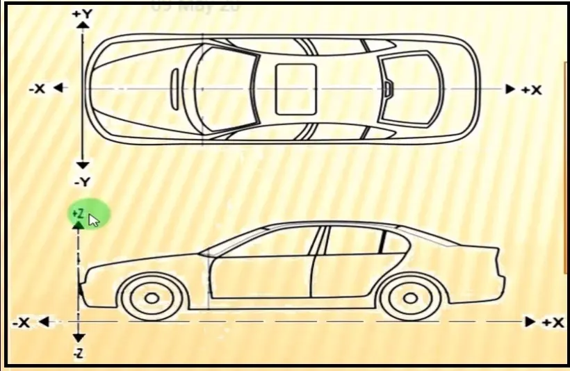
VEHICLE ORIENTATION: All vehicle product drawings are identified numerically relative to three vehicle planes described and shown below.
X= longitudinal direction (fore & after-F/A) or (Front O line-FOL).
Y= transverse direction (Cross car-C/C) or (Centre O line-COL).
Z= Vertical direction (Up & down- U/D) or (Bottom O Line-BOL).
7. Body plane system & its essentials:
Body planes are the reference plane in an automotive car. These planes are used to define the GD & T of all car parts in a automotive domain.
Body planes are three mutually perpendicular imaginary planes. These are generally considered to be present at the driver position or sometimes at the engine location or at the front end of the car depending on the customer.
The measurements from the body planes to the parts are called as body line dimension.
These body planes are called as
FOL Front “O” line.
COL Centre “O” line
BOL Body “O’ line
The measurement along FOL or X-axis is called as F/A Front aft.
The measurement along COL or Y-axis is called as C/C Cross car.
The measurement along BOL or Z-axis is called as U/DUP down.
In below figure origin is somewhere below driving sheet as it depends or changes from customer to customer. But axis system is commonly same.
Bodyline dimensions are essential for the reasons stated below,
- It defines the exact position of each product in the vehicle w.r.t. a fixed origin.
- It ensures flawless design for assembly.
- While designing lines, all the designs are carried out relative to the bodyline, viz, fixture, turn table etc.
- It assists in easy location of different parts in a vehicle.
- It aims in creating a standardized system.
- It assists in quality checks.