Week 2:- BiW Fixture Basics Challenge
Q-1 what is process of project execution activities ?
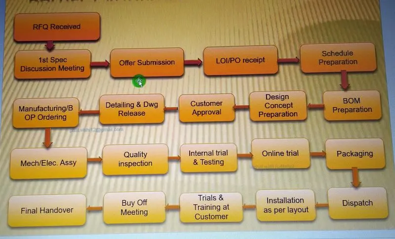
- Above image shows the process of project execution activities.
The various steps involve are described below.
1) RFQ recieved : This is first step in any project. RFQ stands for REQUEST FOR QUOTATION. In this the customer specifics this requirments , specifications etc in form of documents or data. also
customer specifies its technical offer , commercial offer , how the project will be executed , timeline to complete the project.
2) 1st spec disscussion & offer submission : In this the documents related to technical offer , commerial offer , project execution , project timeline to complete the project is prepared. The time
required for 3D design , analysis of design , drawing & detailing , manufacturing , assembly & commisioning etc is considered. The cost of operation is also considered.
3) LOI / PO reciept : The customer will the study the offer submitted , he will also take quotations from others. The customer will study all the offers , compare offers & select the best offer which
suits. The customer will generate PO means purchase order to start the work.
4) Schedule preparation : After recieving the PO the project officially starts. The timeline is fixed so there should plan to beat the deadline & to complete the project. All the activities are taken into
account like PO reciept , 1st meeting , design data analysis , 3D design preparation & stimulation etc.
5) BOM preparation : Bill of material is prepared for the project like the BO parts , grippers , cylinders , motors etc which are required.
6) Design concept preparation : The customer gives data or specifications for the design. Based on that data the design process is start which fulfills all the customer requirements.
7) Customer approval : After designing the concept the approval of customer is required. Customer checks the design fullfills the requirement or not according to the technical offer. By doing the
necessary changes final approval is taken from the customer.
8) Detailing & DWG release : After the approval from customer DWG is released which shows detail specifications of all the parts required like dimensions , qty , specifications etc.
9) Manufacturing BOP ordering : The BO parts like motors , cylinders , sensors , grippers etc required for manufacturing are ordered as per design specifications.
10) Mechanical & electrical assembly : Once the parts are received they go for prior quality control checking. In this all the parts are checked as per the specifications. After QC checking the
mechanical & electrical assemblies are prepared as per requirements.
11) Quality inspection : After the assembly again the quality is checked this time all the dimensions , positional accuracy , co-ordinates are checked by using CMM machine.
12) Packaging & dispatch : The assemblies are packed in proper manner because in transportation the fixture will get damaged hence it distorts the geometry of the fixture & also the functionality
of the fixture. Once the packaging is done the assembly is dispatched to the customer's address.
13) Installation as per layout : Layout is space defined for the parts like fixtures , robots , according to functionality , application , process , sequence etc. The layout is done in very initial level
& according to that installation is done.
14) Trials & traning at customer : Production trials are taken at customers end. In technical offer we have specifed the quality benchmarks for the fixture , the capability of the fixture for production
15) Buy of meeting & final handover : After the trail & training customer check all the prescribed things in the offer are done or not. Sometime customer want some addtion work also , so according
to the requirement all the points are closed & after that the project is handovered to the customer.
Q-2 What are types of joining process ?
- Joining process are the process of joining two metals parts . Also defined as joining of two metal parts either temporarily or permanently.
- Joining processes include welding, brazing, soldering, mechanical fas- tening, and adhesive bonding. Mechanical fastening can be used to provide either temporary orpermanent joints, while adhesive bonding, welding, brazing, and soldering processes are mainly used to provide per- manent joints.
- There are three types of joining , Joining processes are typically divided into three categories: Mechanical joining, welding, and adhesive bonding. Medical devices are manufactured using a variety of materials, from metals to polymers to ceramics, and can be joined using all three methods.
1. Mechanical joining :
- Mechanical joining includes bolting, riveting, caulking, shrink fitting, and folding, all of which join workpieces by using mechanical energy. Metallurgical joining includes fusion welding, pressure welding and brazing/soldering which use different energies.
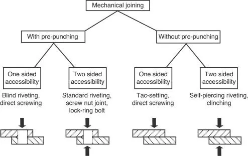
Mechanical joining – also called joining by forming – has become interesting for the automotive industry due to the request to reduce fuel consumption and thereby emissions.
In order to reduce weight on the car body, the usage of lightweight materials in the body-in-white application has increased. This includes aluminium, high-strength steel alloys, polymers, and composites. Here the different type of mechanical joining becomes important.
All mechanical joining methods are cold forming techniques. One general benefit for all mechanical joining methods is the mobility of the material after joining. At the same time mechanical joining offers an impressive strength.
Mechanical joining is divided up into two main groups:
Without fastener
With fastener (riveting)
Advantages of mechanical joining
- No thermal structural transformation of work pieces
- Numerous choice of material of rivets, sizes, forms etc.
- High strength capacity
- Mobility of material after joining
- Easy to control quality
- Good environmental behavior – no emission or polution
Disadvantages of mechanical joining
- Can be difficult or impossible to repair joints
- Many rivets are patented and may mean higher cost
Riveting
Riveting is the general term for joining with rivets / fasteners. You can find many types of riveting where we have described some of them below.
The principle of riveting is to join two or more plates mechanically by a joint. The joint is placed in a hole in the plates and forced mechanically to deform and thereby lock the plates.
Self-piercing riveting (SPR)
The principle is that it fastens together two or more sheets of material mechanically with a self-piercing rivet. The rivet pierces the top sheet and the joining is achieved when the rivets pierces the bottom sheet partially, deforms the material into the die, and thereby forms a mechanical interlock. Often a layer of adhesive is used to keep the sheets in place while riveting.
Advantages of the self-piercing riveting method
- Working with un-weldable material or material that is very difficult to weld
- Working with dissimilar materials
- When protective coatings need as little damage as possible
Disadvantages of the self-piercing method
- The result doesn’t give a perfectly flush surface
- Attention in design needs to be on the possibility of corrosion due to the possible accumulation of water or moisture in the gaps between rivet and sheets
The challenges working with Self-piercing riveting (SPR) method
- To find the best suitable rivet in form, size, and material
- To obtain the correct level of penetration of the rivet
- To obtain the perfect level of penetration of the rivet
- To predict the static and dynamic behavior
Blind Riveting
The blind riveting method is very often used in aircraft industry, shipping, but also in the electronics industry. Some call the rivets “blind rivets” others “hollow rivets”.
Advantages of Blind Riveting
- Very fast to install
- Can be installed from single side
Disadvatanges of Blind Riveting
- The tail shows on the back
Punch Riveting
The joint is created by the deformation of the die-side and thereby locking the rivet by filling the ring grove.
Clinching
The joint is produced at the clinched point directly out of the sheet material components – meaning without fastener. The clinching method can be used for lightweight sheet materials such as low-density metals, and nonmetals. Conventional clinching can be used for joining metal–metal combinations. Some metal–non-metal pairs can only be connected by hybrid clinching or modified clinching.
When talking about clinching you divide them up into “round” and “square” clinching.
Clinch riveting
Clinch riveting is a combination of the clinch process and the riveting.
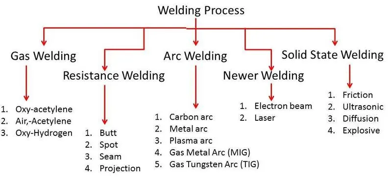
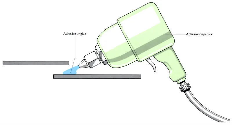
Q-3 What is resistance welding & its application in automotive sectors?
• Spot welding is often selected for joining sheet metal fabrications, stamping and assemblies
because it is fast, reliable and economical. However, numerous design considerations can affect
the quality and cost of the weld, among them: size of the spot weld, accessibility, positioning,
materials and thicknesses being joined, and the number of spots needed to attain the desired
strength.
• Often, spot welding is the method of choice for assembly of entire enclosures, cabinets and multi
part assemblies.
• It is always useful to consult with the metal former in the design stage when questions arise
regarding the part design, application of spot welding or, control of spot welding cost for a particular
design.
• Number of welds, weld size, and location are decided by evaluating strength requirements of
application
• Low carbon steel is most suitable for spot welding. Higher carbon content or alloy steels tend to
form hard welds that are brittle and could crack
• Aluminum can be welded using high power and very clean oxide free surfaces.
• Aluminum, tin and zinc need special preparation inherent to the coating metals
• Adequate access for spot welding should be considered
• It is best to choose the same spot weld size, to minimize setups and increase throughput.
• The mating parts can be self-jigged for easy location prior to welding. This can be done by lancing
one part and locating in a corresponding slot in the other part; or by boss type extrusion, weld
buttons, in part locating to a slot in the other. This type of design can often eliminate the need for
external fixtures.
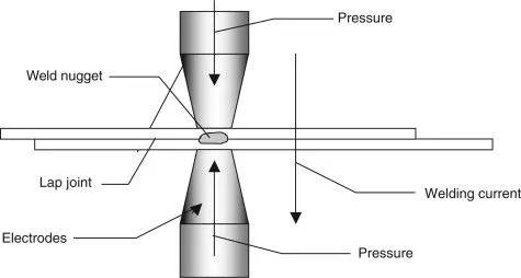
• Ideally, equal thicknesses of two sheet metal parts to be joined produces an evenly distributed
weld nugget within the two layers. When this is not practical, materials of different thicknesses can
also be joined and produce a centered weld nugget by using a larger electrode on the thicker
member.
• At a ratio above about 3-to-1 (thickest to thinnest member), spot welding becomes difficult. At this
point, another joining method should be considered--for example, projection welding.
Applications :
- Resistance welding is widely used in automotive industries.
- Projection welding is widely used in production of nut and bolt.
- Seam welding is used to produce leak prove joint required in small tanks, boilers etc.
- Flash welding is used to welding pipes and tubes.
Q-4 What is fusion welding & types of fusion welding & its application in automotive sector ?
- Fusion welding is process which uses heat to join or fuse two or more materials by heating them to melting point. The process may or may not require the use of filler material. External application
of pressure is not required for fusion welding process.
- Fusion welding process can be grouped according to source of heat , for example electric arc , gas , electrical resistance & high energy.
1. Shielded metal arc welding (SMAW).
- The term "arc-welding" describes the process of fusing metal sections together by
way of heat generated with an electrical spark, or "arc".
The process that will be described in this series of programmes is known as
"Shielded Metal-Arc Welding" or "SMAW". The process is performed manually, that
is, a welder has to physically manipulate the welding action, by "hand". For this
reason the process is also known as "Manual Metal Arc-Welding" or MMAW.
SMAW is mostly associated with the welding of "mild carbon-steel", low alloy steel
and certain other "weld-able materials".
In essence the process of arc welding relies upon an electric current flowing in a
"closed circuit" or "loop". The current is caused to jump across a gap, created
between an electrode and the "work", or the "base metal" (sometimes referred to
as "parent metal").
When a current jumps over a gap a "spark" occurs and heat is created.
The temperature reached inside an arc is in the region of 6000˚C. Metal in
direct contact with the arc melts and fusion takes place within the spark
area.
An "electrode", also known as a welding-rod (or welding wire), made from the
same (or similar) material as the base metal (work piece), is used to direct the
current onto the base metal. The electrode burns away (melts) and deposits
metal into the welding joint.
Welding rods (electrodes), used with SMAW processes, are coated with "flux"
that burns away during the "arcing" process.
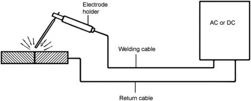
- HOW DOES THE "SHIELDED METAL ARC PROCESS WORK?"
The temperature generated within the arc is sufficient to cause most metals to melt.
The most commonly welded metal, using the SMAW process, is "mild-steel" (also
called "low carbon-steel).
Within the arc "fusion" occurs between the "base-metal" and the electrode. The
electrode, which has a metal core of similar metal to the base-metal, "melts" into
the weld adding "filler" into the joint.
- In the "fusion process", the flux coating that surrounds the electrode, burns
away and in this way creates a "shielding gas" which envelopes the "molten
metal".
This "shield" of gas prevents oxygen, in the atmosphere, from entering the material.
In other words the gas prevents the metal from "oxidising" whilst it is in the molten
state.
Flux also mixes with the molten material causing "impurities to rise to the surface of
the weld-bead. A hard "temporary protective layer" known as "slag", forms upon
the surface of the weld-bead as the metal cools.
Slag protects the weld during cooling, but has to be removed before further welding
can take place upon an existing bead. A "chipping hammer" is used for removing
slag.
2. Metal inert gas (MIG).
- It is also known as Gas Metal Arc Welding.
- In Gas Metal arc welding,
- If gas used is inert gas like Helium, Argon, then it’s called
- Metal Inert Gas (MIG) Welding.
- If gas used is reactive gas like CO2, O2, then it’s called
- Metal Active Gas (MAG) Welding.
- It is a high deposition rate welding process.
- The metal wire is fed from a spool.
- This is a semiautomatic welding process.
- MIG welding is a gas shielded metal arc welding process using the heat of an electric arc between a continuously fed, consumable electrode wire and the material to be welded.
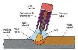
- Metal is transferred through a protected arc column of inert
gas to the work.
- A wire of copper coated mild steel is fed continuously from a reel
through a gun with melting rate up to 5 m/min.
- Current through wire ranges from 100 to 400 A depending upon
the diameter of wire.
- The welding machine is a dc constant voltage machine.
3. Tungsten inert gas welding (TIG).
- Gas Tungsten Arc Welding (GTAW) also known as Tungsten Inert Gas welding (TIG) is an electric
arc welding process that produces an arc between a non-consumable electrode (tungsten which does not
melt due to its high melting point) and the work piece to be welded. The weld is shielded from the
atmosphere by a shielding gas that forms an envelope around the weld area. However, a filler metal is
usually used in the process . The weld area is protected from atmospheric contamination by an inert
shielding gas (argon or helium), and a filler metal is normally used.
- Manual gas tungsten arc welding is often considered the most difficult of all the welding processes
commonly used in industry. Because the welder must maintain a short arc length, great care and skill
are required to prevent contact between the electrode and the workpiece. hand while manipulating the
welding torch in the other .
- Similar to torch welding, TIG normally requires two hands, since most applications require that the
welder manually feed a filler metal into the weld area with one .
TIG is most commonly used to weld thin sections of stainless steel and non-ferrous metals such
as aluminum, magnesium, and copper alloys. The process grants the operator greater control over the
weld than competing processes such as shielded metal arc welding and gas metal arc welding, allowing
for stronger, higher quality welds.
- Gas Tungsten Arc Welding(GTAW) is most commonly used to weld stainless steel and nonferrous
materials, such as aluminum and magnesium, but it can be applied to nearly all metals, with a notable
exception being zinc and its alloys. Its applications involving carbon steels are limited not because of
process restrictions, but because of the existence of more economical steel welding techniques, such
as gas metal arc welding and shielded metal arc welding. Furthermore, GTAW can be performed in a
variety of other-than-flat positions, depending
on the skill of the welder and the materials being welded.
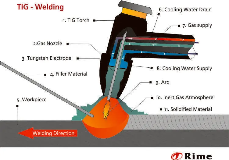
- Working principle:
An arc is established between the end of a tungsten electrode and the parent metal at the joint line. The
electrode is not melted and the welder keeps the arc gap constant. The current is controlled by the
power-supply unit.
A filler metal, usually available in 1 m lengths of wire, can be added to the leading edge of the pool as
required. The molten pool is shielded by an inert gas which replaces the air in the arc area.
Argon and helium are the most commonly used shielding gases.
The process may use direct current electrode positive, direct current electrode negative or alternating
current. The chart above indicates the operating characteristics of each of these current types.
DCEN or “straight polarity” is used for welding most materials other than aluminium. The electrode
tip geometry is generally a sharp point with a small blunted end since most of heat balance is on
melting of the base material.
DCEP or “reverse polarity” is rarely used since it results in low penetration. Also the constant
bombardment of the tungsten electrode by electrons in the DCEP mode degrades the electrode.
Alternating current(AC) is used primarily to weld aluminium, which has a tenacious oxide surface
layer. Although the diagram above states that there is a 50% cycle from DCEN to DCEP, it is possible
through solid state electronics to vary the amount of time at each polarity and also the current at each
polarity.
High-quality welds in metals such as aluminium, stainless steels, Nimonic alloys2 and copper in
chemical plants; sheet work in aircraft engines and structures; Mainly thin sheets.
Nimonic2.
4. Plasma arc welding (PAW).
- The PAW (Plasma arc welding) method is related to GTAW (gas tungsten arc welding). This arc can be formed among the metal as well as an electrode. The major difference among the PAW and GTAW is that in PAW, the welder is capable in placing the electrode in the torch’s body; so this will allow the PAW to be divided from the protecting gas.
- Afterward, the plasma is fed throughout a nozzle which will compress the arc to force the plasma away at high speed as well as temperature. The plasma arc method utilizes a non-consumable tungsten electrode & an arc can be formed by strengthening the plasma throughout a bore nozzle. This arc welding can be productively applied to every metal that can be connected with the help of the gas tungsten arc welding technique.
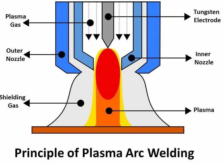
- Plasma ARC Wielding Working Principle.
The plasma arc welding is method wherever a coalescence is generated with the temperature which is developed from a special setup between a tungsten alloy electrode and the water-cooled nozzle (Non transferred ARC ) or between a tungsten alloy electrode and the job (transferred ARC). In this type of winding, there are three types of gas supplies being utilized namely plasma gas, shielding gas, and a back-purge gas. Plasma gas supplies throughout the nozzle turn into ionized. The shielding gas supplies throughout the external nozzle & protects the join from the environment. Back-Purge gas is mainly used when particular materials are being used.
Automotive applications of arc welding :
- Used to weld the chassis part in an automobile.
- Arc welding wire for automotive steel sheets.
- To weld the body parts in automotive industry.
- TIG welding is used to join thin stainless steel parts & various piping parts in automotive.
- MIG welding is used in repairing in automotive industry.
Q-5 What is the 3-2-1 principle ?
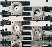
What is it?
A fundamental concern in metalworking is locating the part to be machined, punched, bent, or stamped relative to the work platform (fixture). For example, a CNC machine tool starts its process at a specific point relative to the fixture and proceeds from there. Hence, the accuracy with which a part is machined is quite dependent on the accuracy with which it is positioned in the fixture.
Accurate locating of not just one part, but each and every part that is loaded into the fixture is crucial. Any variation in part location on the fixture adds to the dimensional tolerance that must be assigned to the finished parts.
Additionally, the method of supporting and securing the part in the fixture affects not only dimensional tolerances, but surface finishes as well. This is true because improper supporting or clamping can temporarily or permanently deform the part. Hence, techniques for supporting and clamping must be considered together with the method of locating in order to assure repeatability from part-to-part.
Locating of a part to be machined is a three-step process:
1. Supporting
2. Locating (positioning)
3. Holding (clamping)
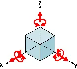
The Locating Process: Degrees of Freedom
In order to completely specify the position in space of a three-dimensional
object (such as the cube that’s shown), we refer to six coordinates:
- Translational position along the X-axis
- Translational position along the Y-axis
- Translational position along the Z-axis
- Rotational position about the X-axis
- Rotational position about the Y-axis
- Rotational position about the Z-axis
These six coordinates are known as the six degrees of freedom of a three-dimensional object. As the double-headed arrows indicate, the translational and rotational positions can vary in either direction with respect to each of the three axes.
To completely prevent movement, all six degrees of freedom must be restricted.
The Locating Process: 3-2-1 Method
We have two objectives when mounting a part in a fixture for machining:
1. Accurately position the part at the desired coordinates.
2. Restrict all six degrees of freedom so that the part cannot move.
A widely used method of accomplishing these two objectives uses the 3-2-1 principle, so-called because it entails three steps that employ three, then two, then one fixed points of known location. Since that adds up to six fixed points, it’s also known as the six point method.
In the three steps of the 3-2-1 method, three mutually perpendicular planes, called datum planes, are introduced, one at each step. These three planes define the workpiece position, and together with opposing clamping forces fully constrain the part. Let’s take a look at the details of the 3-2-1 method.
First Plane
Geometry tells us that three points are required to define a plane. This is the "3" in 3-2-1. So, three specific points are used to define the first plane. Fewer than three points cannot define a plane, and in the real world dimensional tolerances mean that four or more points will not be coplanar. A real-world, less than ideally perfect part placed on four or more reference points will, in fact, rest on only three of the points due to its less than perfect surface. Different parts may rest on different combinations of three points, resulting in variation between finished parts. A stool can be used to illustrate this concept. A two-legged stool would certainly be unstable. A three-legged stool sits rock-solid. A four-legged stool is often found to rock. In the illustration, a three dimensional part, represented by a cube, is placed on a datum plane defined by three support points. The part’s six degrees of freedom have now been reduced to three. It can still move along the X or Y axes, and it can still be rotated about the Z axis. (The part cannot move along the Z axis because it is held against the plane by clamping force.
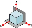
Second Plane
A second plane, if it is perpendicular to the first, can be defined by two points, the "2" in 3-2-1. The part is now constrained to one degree of freedom: movement along the Y axis. (The part cannot move along the X or Z axes because it is held against the planes by clamping force.)
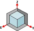
Third Plane
A third plane, if it is perpendicular to both of the first two planes, can be defined by one point, the "1" in 3-2-1. The part is now entirely constrained. It cannot move along or rotate about the X, Y, or Z axes. (Remember that the part is held against each of the three planes by clamping force.
Machined is Best
It’s best if the workpiece surfaces intended to contact the support points are machined. Cast surfaces are usable, but then tend to create tolerance problems. Machined holes are the number one choice. Two machined holes can be used to eliminate all but one degree of freedom.
Repeatability
Repeatability
Repeatability is a paramount concern. It means that each part should be nearly identical to each other part coming off the same fixture. "Nearly identical" actually has a specific, quantifiable meaning: key dimensions of all parts produced on the same fixture must fall within defined tolerances.
In order to stay within tolerances, it’s best if the workpiece surfaces intended to contact the support points are machined. Cast surfaces are usable, but they tend to create tolerance problems. Machined holes are the number one choice, because two machined holes can be used to eliminate all but one degree of freedom.
The next best feature to use for consistent locating is machined surfaces at right angles. The "machined surface" desired here can simply be a tab or small flat specifically included for locating purposes.
Repeatability is achieved through application of the 3-2-1 method to the three aspects of the locating process:
1. Supporting
2. Locating (positioning)
3. Holding
Supporting
- The part is supported from "below" with reference to the Z axis. (Introduction of the first reference plane.)
- Gravity positions the part against the support locator.
- Provide adjustable auxiliary support points as needed to prevent deflection.
- Vertical location with respect to the fixture is now established
- The part is positioned horizontally, in the X-Y plane. (Introduction of the second and third reference planes.)
Holding
- The part is clamped against fixed locators. Therefore, a known and unvarying position of the part is maintained with respect to the X, Y, and Z axes.
- One strap clamp or clamp arm will restrict the workpiece in three dimensions due to friction between the workpiece and clamp. However, friction alone may not be enough to prevent the workpiece from moving during machining.
- Cutting forces will not move a properly supported and clamped part.
Locating
- The part is positioned horizontally, in the X-Y plane. (Introduction of the second and third reference planes).
Summary: Clamping Rules of Thumb
- Define three reference planes on the workpiece and fixture.
- Provide one opposing clamping force opposite each plane to restrict movement.
- When in doubt, rely on additional cylinders to take up uncertainty.
Mechanical and Hydraulic Workholding
Holding a workpiece in place can be done in a variety of different manners. For those just getting started or even those with vast experience in manufacturing, choosing the right method is not always easy. What are the benefits of each method? What are the disadvantages? How do I get started? What types of components do I need? How do they work together? How do I know it is going to work? The next issue of Enerpac University will answer these questions and many more as we present a guide to mechanical and hydraulic workholding, and even offer a combination of the two that incorporates the best features of both
Q-6 Define body co-ordinate systems ?
- Body coordinate system
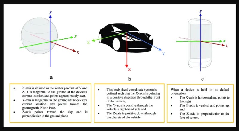
- In general BCS is also called as car line or body line.
- Car line are the grid lines shown on the fixture , which virtually represent the same location in the BIW. All the car line on fixture display the coordinate at corner for referance with these lines one can
easily relate the location in BIW .
- Maintaining x , y , z co-ordinates in fixture is very important factor.
- We should try that the co-ordinates of locating & clamping points should not be in three decimel , they must be in whole number or single decimel.
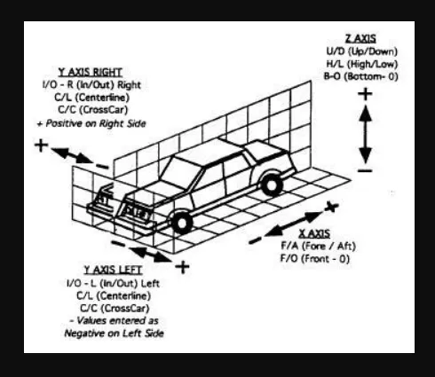
Q-7 Elaborate body plane system & its essential.
- Body planes are three mutual perpendicular imaginary planes. These are reference planes in automotive cars which are used to define GD & T of all parts in automotive domain.
- The measurement from body planes to parts are called bodyplane dimensions.
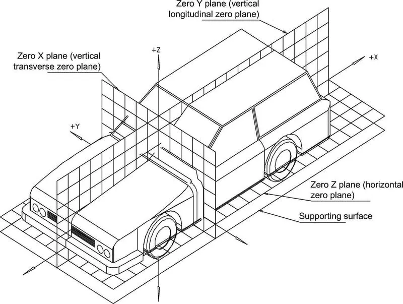
- Bodylines dimensions are essential for below ressons :
1. It defines exact position of each product in the vehicle w.r.t a fixed origin.
2. It ensures flawness design in assembly.
3. It assist in easy location of diffrent parts in the vehicle.
4. It aims in creating a standarized system.
5. It assist in quality check.
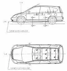
- Below images shows use of planes to define length , width & height of any vehicle.