Week 2:- BiW Fixture Basics Challenge
Chllenge-2 Week 2-BIW fixture Basics Challenge
Q1. What is the process of project execution activity?
Project execution entails carrying out the previously devised plan. It entails carrying out all of the activities that were planned in the previous processes of the project cycle. The project activities are carried out in accordance with the plans, sequence, and procedures established in order to meet the project's requirements. The goal of project implementation or execution is to achieve the desired results.
Project Execution Process Flow Chart
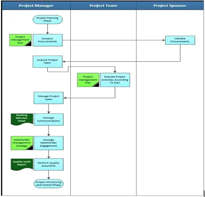
The objectives of the project execution process are to:
- Make sure that activities being taken out follows the management plan.
- Assemble the teams involved, advance and maintain it during the lifecycle of the project
- Create deliverables using the project plan, assess processes and plans involved to deliver
the overall output. - Ensure that the project team is managed effectively so that their efficiency is maximized and all issues are properly addressed.
- Ensure that there is no gap in the communication channels to enable information to bereceived and responded on time.
- Guarantee that excellence project execution is undertaken to ensure that quality is obtained.
Conclusion
To make the project plan a reality and deliver the expected results, all actors in the project execution process must carefully and effectively carry out all activities. As a result, this information is critical for project managers and other stakeholders directly involved in project implementation.
Q2. What are the types of joining processes?
- Resistance spot welding
- Resistance Projection welding
- Resistance seam welding
- Arc welding (Manual metal arc welding, Metal inert gas (MIG) welding, Tungsten
- inert gas(TIG welding), Submerged arc welding, Plasm arc welding)
- Mechanical Fastening
- Self-piercing riveting
- Hemming process
- Adhesive Bonding
Q3. What is resistance welding & its application in the automotive sector?
Resistance Welding commonly divided in three types
I. Resistance spot welding
It is used to join sheet metal and shaped copper-chromium or zirconium alloy electrode used to apply the pressure and convey the electrical current through the workpieces. Heat is developed mainly at the interface between two sheet and interface material will be melted. By the application of force sheet will be joined together. It take short time to complete leads in very fast process with very good strength.
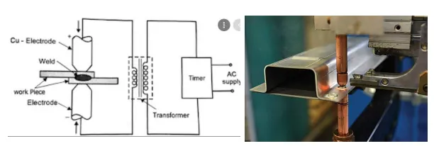
II. Resistance Projection welding
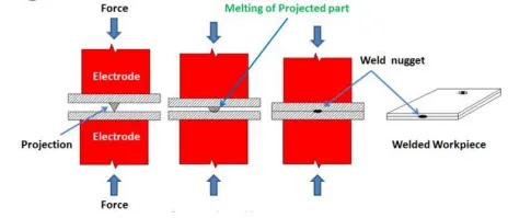
It is used for joining sheet metal component with embossments by directly applying opposing forces with electrode specially design to fit the shape of the workpiece. Large deformation will
take place in the projection part of the workpiece involving high.
III. Resistance seam welding
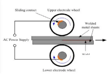
It is sheet metal joining operation in continuous flow for long space. Under this welding the opposing force applied through the electrodes consisting of rotary wheel. Mostly, it is used in
container manufacturing, radiators and heat exchangers etc.
Q4. What is fusion welding & types of fusion welding with its application in the automotive sector?
Fusion welding is a method of joining or fusing two or more materials by heating them to their melting points. A filler material may or may not be required for the process. External pressure is not required for fusion welding processes, with the exception of resistance welding, which requires significant contact pressure during welding for sound joining. A heat-affected zone is formed in the material as a result of the high temperature phase transitions inherent in these processes. Having said that, there are five distinct types of fusion welding, including the following.
Classification
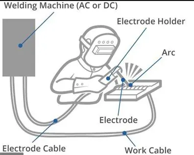
Arc welding is one of the types of fusion welding. Arc welding is a method of joining two pieces of metal together that uses an intermediate filler metal. This is accomplished by completing an electrical circuit to generate an electrical arc. The centre of this electrical arc is 3593 °C. This electrical arc is formed at the filler metal's tip. As the arc melts the metal, it is moved along the gap between the metals by either a person or a machine, forming a bond. Arc welding can also be done underwater, making it an ideal solution for offshore welding projects.
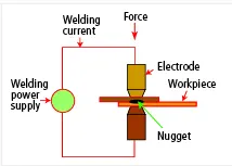
Resistance welding is performed using two electrodes. Each comes into contact with one of the pieces being joined. The two parts of metal are then pressed together between the electrodes and an current is passes through them. The pieces of metal begin to heat up at the point where they come into contact. The current is passed through the metal until it is hot enough that the two pieces melt and conjoin.
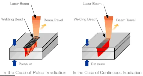
Conduction welding also known as laser beam welding or radiation welding, is a highly precise form of fusion welding. "Laser" is an acronym for Light Amplification by Stimulated Emission of Radiation. The laser emits light in bursts called pumps. These bursts are aimed at the seam of the metals desired to be conjoined. As the laser bursts it is guided along the seam. These intense bursts melt the metal. The two metals when melted mix with each other. Once it has cooled the seam created is a strong bond. Lasers are efficient because they can be configured to make multiple welds at once. The laser beam can be split and sent to multiple locations greatly reducing the cost and amount of energy required. Laser beam welding finds applications in the automotive industry.
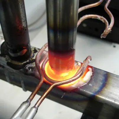
Induction welding is a form of resistance welding. However, in this no points of contact between the metal being welding and the electrical source or the welder. In induction welding a coil is wrapped around a cylinder. This coil creat a magnetic field across the surface of the metal inside. This magnetic field flows in the opposite direction of the magnetic field on the inside of the cylinder. This process heats the metal and causes the edges to melt together. Induction welding is distinguished from all other types of fusion welding because it is the only one in which there is no direct contact between an object’s surface and the heat source.
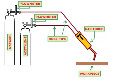
Oxyfuel Welding
It is a type of chemical-based fusion welding. Oxyfuel welding process involves the use of a flame for heating and join surfaces, with oxygen as the fuel source. The oxygen, which is the basis on which oxyfuel welding works. The oxygen fuels the fire to create a hot flame in excess of 4,500°F. Oxyfuel welding typically uses a combination of oxygen and a flammable gas to create a hot flame to join objects.
Applications
The Fusion welding has been a key factor of in the creation of modern civilization due to its major application in many area. Besides bolts and rivets, there are no other practical method for joining pieces of metal securely. The Fusion welding is performed in the manufacturing of many system everyday items including airplanes, cars, and structures.
Q5. What is the 3-2-1 principle?
Any 3D body/part have three axis along x-axis, y-axis and z-axis. It can move along any of these axes or any of its movement can be released to these three axes. At the same time the body can also rotate about these axes too. So total degree of freedom of the body along which it can move is six. For processing the body it is required to restrain all the degree of freedom (DOF) by arranging suitable locating points and then clamping it in a fixed and required position. The basic principle used to locate the points is desirable below. Locating a part to be machined involves mainly three steps: Supporting, Positioning, and Clamping.
Two main purposes of placing a part on a jig/fixture are:
- Accurately positioning the part at the required coordinates.
- Restricting all six degrees of movement so that the part cannot move.
An extensively used method for obtaining these objectives is the 3-2-1 principle or six degrees of freedom for part location.
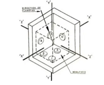
The 3-2-1 method is a work-holding principle where three pins are located on the 1st principle plane, i.e., either XY, YZ, ZX. And two pins are located on the 2nd plane perpendicular to the 1st plane, and at last, one pin on the plane is mutually perpendicular to the 1st and 2nd planes. The aim is to constrain the movement of the workpiece along all three axes.
Q 6. Define body coordinate system?
Body co-ordinate system (BCS) is reference system consisting of a group of points, lines and surface and same is used for the defining the position of point in space in either two or three
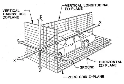
dimension. It is widely used in the automobile industries for drawing of parts, product and process design. It is also known as car line and body line in the automobile industries. The origin of the BCS, OX is defined at the front center of a vehicle, it indicates length of the car. The co-ordinate system OZ is below its underbody indicates height of car and the coordinate system OY indicts width of the car.
Q7. Elaborate body plane system & its essentials.
Body planes are the reference planes in an automotive car presented in the above Figure and used to define the GD&T of all car parts/components. These plane are mutually perpendicular to each other as seen the above figure with the grids. The measurements done from the body planes to parts known as bodyline dimensions.
Why it is required
- It define the exact position of each product in the vehicle w.r.t. a fixed origin.
- It ensures faultless design for assembly.
- All the design are carried out relative to the bodyline.
- It aims are to create a standardized system.
- Due to these all its helps in proper quality check.
********************************************************End of report************************************88