Week 2:- BiW Fixture Basics Challenge
1) What is the process of project execution activity?
- In projection activity there are many steps involved to finish a particular project. The steps involved are
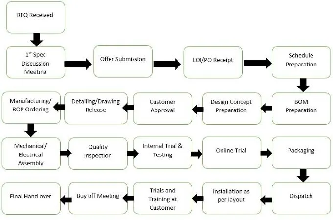
Fig: Process of Project execution activity
a)RFQ
- Request for quotation(RFQ) is first sent by the customer. In this quotation there will be specification about the project with technical and commercial offer mentioned. It also mentioned about how to carry out the project and in how much time required to finish it.
b) 1st spec discussion & offer submission:
- In this the quotation submitted by by the customer is carefully analyzed. Their offer, the execution of project, time required for completion is analyze. Then the buyer will discuss about the execution like drawing, 3D design , the process of manufacturing it ,assembly ,extra charge etc are considered and prepare an offer which is sent to customer.
c) LOI/PO :
- The offer which is sent to customer is analyze by them and purchase order (PO) is generated. The customer will receive n number of offers from the buyers and they choose only one from them which is best from customers perspective.
d)Schedule preparation:
Official project will start once PO is received from customer. A date is fixed to finish the project so as to beat that deadline to complet the project. All the steps are taken into consideration such as 3D design, design simulation, meetings, assembly and etc. All this step will be given time limit to complete and by calculating time for each step or task a deadline is set for completing the project. And if any task cannot be completed within specified time period then a new scheduled is prepared as a backup.
e) BOM Preparation:
- Bill of materials(BOM ) is all the parts that will required for completion of that project.
f) Design concept preparation:
- Customer gives the data required for design in quotation. Base on this data actual design process initialize which satisfy the requirement of customer.
g) Customer approval:
- Once design is ready it requires customer approval for next step to follow. Customer checks the design and will ask if some additional work need to be done. Once all the additional work us completed green light is given by customer.
h) Detailing and DWG release:
- Once design is approved CAD file(DWG) is generated which will have all the details like part dimension ,specifications of each part.
i) Manufacturing BOP ordering:
- Parts required during assembly and manufacturing such as different grippers ,sensors , etc are ordered.
j) Mechanical/electrical assembly:
- Parts received will first go to incoming quality to check if the parts parts are within sepcification or not. Once quality checking is complete mechanical/electrical assembly is design as per requirement.
k) Quality check:
- Once assemblies are ready it is again check to see if it is within specified dimensions, accuracy , etc using CMM.
l) Internal trial,testing & online trial:
- In internal trial fixture is tested if it can perform the operations that it design for . So simulation is done at an initial stage to check fixtures different operations perform like clamping, welding etc.
- In an online trial all the operations are perform on automatic mode and its sequence is observed by customer for the approval for online trial.
m)Packaging & Dispatched:
- The packaging of the assembly should be done properly such that it does not farm the fixture during transportation. If the packaging does not done properly there might be chance that fixture may get damage that can lead to damaging geometry and functionality of the fixture. So it is too priories to do packaging properly before sending it to customer.
n) Installation as per layout:
- Installations at the customer end should done properly. If not done properly then it can alter the functioning,accuracy, sequence of process , etc.
o) Trial & training at. customer:
p) Buy off meeting & final handover:
2) What are the types of joining processes?
- There are two types of joining processes mainly metallurgical and mechanical joining process.
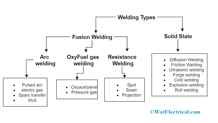
Fig : Different types of welding process
1) Metallurgical joining Process:
- In this process part is join by fusion of part material or fusing different material to join the part like welding , soldering etc.
There are many types of metallurgical process use for joining they are:
a) Welding:
- In welding process the material to be join is melted with the help of electrode and fused together . The heating effect is generated by electric arc through electrode such that the metal is melted along with the electrode or filler metal and the melted mixture solidifies upon cooling to form joint.
- As the electrode moves over the work piece area that's needs to be join, heat is generated through electric arc enough to melt both the electrode and the work piece area. The molten metal will now fuse together to form weld. To protect fusion of metal from surrounding unwanted gases the electrode outer surface contains flux which also melts and protect from outside of the weld area and prevent from corrosion.
- During welding process the microstructure of the welded area gets alter due to high temperature as a result the tensile strength and toughness reduces. Also residual stress develop during cooling which further reduces strength of weld area. For this welding process should be done properly and uniformly . The heating should be uniform during welding and the mixture of metal also should be uniform . Also cooling rate need to be optimize in order to reduce residual stresses.
b) Brazing
- Brazing is a process in which two workpiece are joined together with the help of filler metal. In this the filler metal will melt and acts as a gluing agent between two workpiece. Two workpiece that need to be join are not melted at all only filler metal is melted. In this process temperature should be high enough to melt filler but not the workpiece. Therefore filler metal used in this process will have low melting point than that of workpiece. Flux is used to prevent any unwanted gases present during melting of filler and preventing the joint from getting oxidation or corrosion. The joint is stronger in this process because filler metal can go through small spaces by capillary action. Melting point of filler metal is more than 450℃ .
c) Soldering
- Soldering is a joining process which is similar to brazing process only difference is that soldering process takes place at low temperature than brazing. Here also the filler metal is use to joining two parts but not melting the workpiece. Here also flux is use which will cover the weld surface to prevent oxidation but the flux covering need to clean once weld is cool down to prevent corrosion. The melting temperature of the filler metal is less than 450℃.
d) Adhesive Bonding:
- In adhesive bonding workpiece is join with the help of chemicals known as adhesive. It can be use to join composite like polymer matrix, metal to metal, metal to polymer, ceramics and so on. It does not require any heating or melting it completely depends on chemical reaction of adhesives. It has vey high tensile stress , compression stress, shear stress but it very weak when comes to peeling . To overcome this issue the surface area for adhesive is increase. For proper bonding of adhesive surface needs to be clean, surface area should be large enough for proper bonding , also surface on which adhesive is applied is made rough .
e) Diffusion Bonding
- It is a solid state joining process , can be use to join metals,ceramics and even two different material. Parts which is to be join are place in contact to each other then external pressure is applied from both the sides such that the two contacted surface will diffuse to form a joint. The surface is heated at elevated temperature (50%-90% of the absolute melting point.
2) Mechanical joining
- The best example of mechanical joining is using nut and bolts through threaded hole area in the workpiece. Other examples are screw, rivet caulking etc. The joints are temporary or permanent depending on requirements. The disdvantage is that the hole in the workpiece is exposed to failure of the workpiece itself. So while designing a mechanical joint we we must take failure of workpiece into consideration.
3) What is resistance welding and its application in automotive sector?
- Resistance welding is a type of joining process in which two metal parts are join with the help of resistance to current flowing through electrode which generates heat and pressure is applied to join properly. In this process filler metal is not required and also no flux or inert gases is required which makes it less costly process.
- The advantage of using resistance welding is that it can be use to weld thick materials with ease. It is a automated process of joining which makes welding faster than other process. It can be use to join two dissimilar metal and is more environmental friendly. Because of it high production rate capabilities this process is use in automotive , aerospace industries and many other industries where production rate is very high.
Types of resistance welding application:
a) Spot Welding
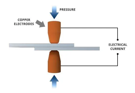
Fig: Spot welding process
- Spot welding is a type of resistance welding proce in which electrode is use to melt a particular spot to weld tow parts together without required any filler metal. The workpieces is join with the help of two shaped copper alloy electrodes which concentrate the current into a spot and simultaneously joining they two work piece. The work piece is held together from the pressure exerted by two electrodes for a define period of time.
- This method is mostly used for welding various sheet metal in the industry. Care must be taken while using spot welding because of heating done is more than required or pressure applied is more there is a chance the work piece can develop hole instead of joint.
b) Seam Welding
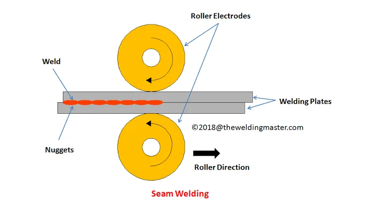
Fig: Seam welding process
- Seam welding process is same as spot welding , only difference is that instead of rod shape electrode it use roller shape electrode which apply the required pressure and the current to the work piece. In this process roller electrode rolls over the work piece at an constant speed and pressure . The welding done on this process can be seam or spot with equal spacing between them. This process is much faster than spot welding. This is used to make leak proof containers.
c) Projection welding
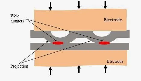
Fig: Projection welding process
- Projection welding is same as spot or seam welding process ie electrode will melt the work piece by resistance to current and along side pressure will be applied along side . The difference is that projection or raise section is made on one or both work piece where weld nugget will form . Projection are made by stamping, embossing etc. It is a modified form of spot welding which is spots are already projected on work piece and only at the projection electrode will melt the metal.
4) What is fusion welding & types of fusion welding with its application in the automotive sector?
- In Fusion welding process it makes use of electrode which when comes on close contact with work piece heat is generated which melts both electrode and the work piece and welds the two work piece. It involves two or more metals which will fused to form a weld. Unlike resistance welding fusion welding does not required any pressure against the workpieces for proper joining.
- Types of fusion welding are
a) Shielded Metal Arc Welding (SMAW)
- SMAW is also known as flux shielded arc welding or manual metal arc welding or also stick welding. It makes use of electrode which will consume when comes in contact with work piece.
- This process uses either AC or DC electric current from power supply which produces electric arc when electrode comes in close contact with work piece. When electrode comes in contact with the metal work piece electric arc is form which produces heat which melts both the electrode and work piece and fused together along with that the flux coating around the electrode also melts and forms a layer of slag around molten metal area and shield the weld area from contaminated gases which can alter microstructure of weld which leads to reduction in strength of weld.
- This process can be use for various thickness of metal. It is often used for heavy duty work involving industrial iron and steel, like carbon steel and cast iron, as well as work involving low and high alloy steels and nickel alloys.
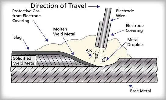
Fig: SMAW Process
b) Metal inert gas welding(MIG)
- MIG is also known as metal active gas welding (MAG) . In this process also a consumable electrode is used which produces electric arc when comes close to the work piece and melting both electrode and work piece and forming a weld. The electrode dose not have flux but in MIG it uses inert gases during welding process as shielding from other contaminated gases present in atmosphere.The electrode dose not have flux but in MIG it uses inert gases during welding process as shielding from other contaminated gases present in atmosphere. This process generally use direct current as power source but alternate current can be use. Process can be automated or semi-automatic.
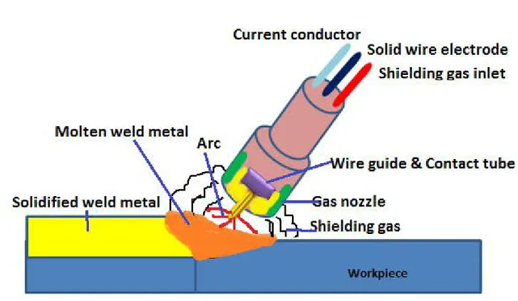
Fig: Metal inert gas welding process
c) Tungsten inert gas welding (TIG)
- Tungsten inert gas welding is all known as Gas tungsten arc welding is unlike other fusion process, in this it make use of a non consumable electrode which produces an electric arc which melts the base metal workpieces and joining them. Since the electrode is non consumable it does not contains any flux but during process it uses inert gas around welding to prevent from oxidation . This process is use for joining thin metal sheets in automotive and aerospace industries. For joining thick sheets it makes use of consumable electrode .
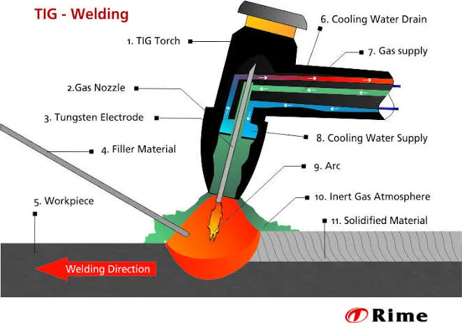
Fig: TIG welding process
Application of fusion welding:
- TIG is used join thin sheets steel with perfection .
- Both MIG and TIG processes are use for automobile restoration for small or heavy duty work.
- MIG is generally used in automotive and aerospace industries because it is easy to use, process is fast and dependable and also automatic.
- TIG is use for joining pipes in automotive industry like exhaust system and etc.
5) What is the 3-2-1 principle?
- The part that is too be machined should be located precisely such that when CNC will start to machining fixture holds the work piece precisely throughout the operation or else tolerance might get affected and part may get deform. Also if clamping of part is not done properly it can affect the final surface. Hence we use 3-2-1 principle for properly locating the part before machining.
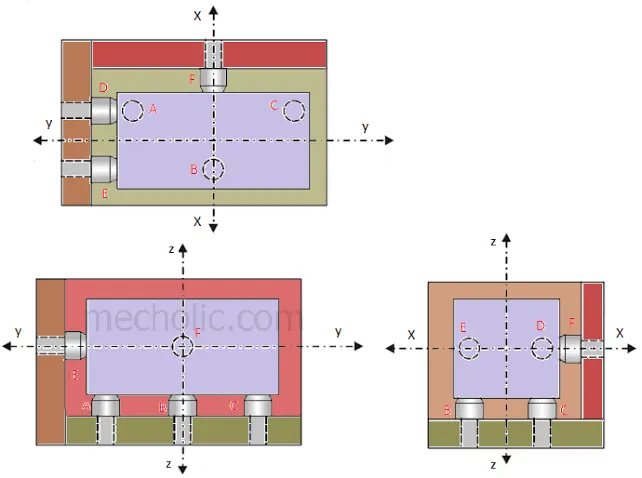
Basic principles of fixture design
- Locating point
- Locating the points is very necessary fir properly functioning the process. The setup should be smooth such that the loading and unloading of work piece should be fast and less time consuming. With use of guide pins ensures that work piece is loaded smoothly.
- Foolproof
- Foolproof design of jigs and fixture ensures that work piece is loaded as planned and not any other manner.
- Reduction of idle time
- Design of jigs anfmd fixtures are such that the loading , unloading, machining, clamping is done smoothly without any interruption.
- Weight of jigs and fixture
- Jigs and fixture should be easy to handle, aquire less space and less costly without loosing its rigidity.
- Jigs provided with feet
- Sometimes jigs are provided feet so that it can be placed firmly on table.
- Materials for jigs and fixture
- Jigs and fixture are made up material like stainless steel, cast iron, high carbon steel to avoid wear and tear.
- Clamping device
- Clamping device should be such that it should hold the workpeiece firmly even under stress and strain during operation.
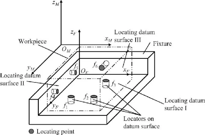
3-2-1 Principle
- For locating a part which will undergo machining involves 3 steps, they are supporting, positioning and clamping
- Two reasons for putting workpiece on jigs and fixture are
a) Precisely locating the workpeiece to be machined with desired coordinates
b) Restrict six degrees of freedom so that part cannot moved.
- Most extensively and cost effective method use for locating the points is 3-2-1 principle.
- In this principle three pins are located in 1st principle plane on either XY,YZ,XZ. Two pins are located in 2nd principle plane perpendicular to 1st plane and one pin is located in 3rd plane mutually perpendicular to both the plane.
Design objective of jigs and fixture
- Before designing jigs/ fixture the designer should consider the following
- Tool should be easy to operate thereby increasing the efficiency.
- Tool should be foolproof such that it prevent wrong position of workpeiece while loading.
- The manufacturing cost should be as low as possible.
- Quality of parts produced should be consistent .
- The tool should be safe to work around.
6) Define Body coordinate system?
- Body coordinate system is the reference point system which is a set of points or lines or surfaces is use to define the exact position of points in 2D or 3D.
- Body coordinate system in fixture design is known as car line or body line.
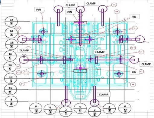
- Cat lines or body lines are the grid lines which is shown on the fixture is virtual representation of the same point in BIW . The car lines in the fixture shows the coordinate corner for the reference. With the. help of these lines anyone can relate the location in BIW.
- It is possible to make a fixture by using single coordinate hole provided in the fixture as this point represents the car line coordinates. Coordinates of body is mentioned near the hole.
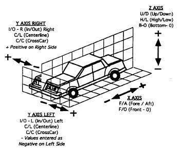
- It is important that we maintained the X,Y and Z coordinates in the fixture.
- Also it is important that the coordinate points of location and clamping are not in three decimal . The points should be as a whole number or max with one decimal . If these coordinates points are properly maintain the base structure of BIW is automatically maintain.
7) Elaborate Body plane system & its essentials.
- Body planes are imaginary plane which are mutually perpendicular to each other which are used as reference plane on automotive car. Also these plane is use to define geometric dimensions and tolerances .
- Bodyplane dimension is the measurement from body planes to part.
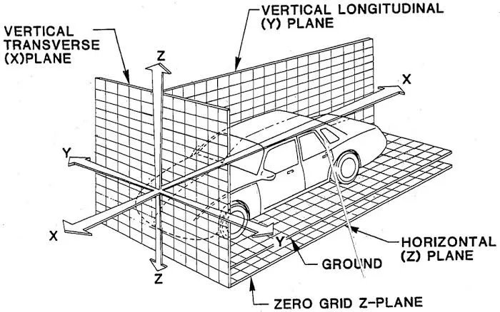
- Bodyline dimension is important for reasons mentioned below
1) It exactly defines the position of each part present in a vehicle with respect. to fix origin.
2) It ensures defect free design in assembly.
3) It helps in locating any part in the vehicle.
4) It helps in improving quality.
5) It aims to make system standardize.