Week 3:- BiW Fixture Design Methodologies Challenges
1) What is Design methology?
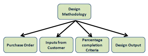
- Design methology is basically the steps involving in the concept of designing. stages of fixture design. In the concept of design we have to take some majors into consideration and then start the process of designing. Design methology consists of four major categories they are purchase order, input from customer, percentage completion criteria and design output.
- Purchase order
- PO is generally confirmation given by the customer against the quotation.
- Input from customer
- Input from the customer is the details given by the customer of the design and how to execute that particular design operation.
- Percentage completion criteria
- Percentage completion criteria is actually the schedule of each stages required to complete a particular project within given time period.
- Design output
- Design output in BIW fixture design is giving the part details file to the customer ie 3D, 2D and also the Bill of Material. All small details of the part is submitted to the customer end.
2) What are the inputs required from the customer to start designing a Fixture?
- To design a fixture the inputs required from the customer are
- Functional Requirement
- Functional requirement is the function that will perform by the fixture design like welding, riveting , etc. It is given by the financial department.
- Preferred Standard components
- It is basically the standard components required for the customer or they already have it. We need to design according to the standard components of the customer already has it then a lot of time and effort is saved since we do not have to design the components.
- Car products
- Car products is a data file such as 3D file or read file which is use to learn different kind of geometrical. tolerances and Principle locating points . Such that it helps in identifying the clamping edge and fixing proper position.
- Layout
- It is the layout of the whole assembly line to study the process and the flow.
- Ergo data
- It is the data required for manual operators. It provides the maximum or minimum height of platform for operator to each fixture . It also provides loading height, safety operating zones etc.
- Weld study
- Weld study is the study of different welding guns and where the welding need to be done on part.
- Standard detailing template
- It is the standard detailing given by the company. Detail template is given by the company to make details of components and its dimensions.
3) What is the inputs we get from "Car products"?
- Car products is a data file such as 3D file or read file which is use to learn different kind of geometrical. tolerances and Principle locating points . Such that it helps in identifying the clamping edge and fixing proper position.
The inputs we get in car products are
- GD&T
- It stand for geometric dimensions and tolerances. In gives the best position for locating the pins. How the components will going to rest and also clamp, and gives slide stroke information of each station.
- Part list
- There are many assemblies that takes place and each assembly will be required different parts.
- Part list generally means that what type of assembly is going to be and what kind of parts will be required for that assembly.
- Part list will have part names or part numbers and each part will have different names or number.
- The revision
- In revision one component will have 21 divisions, so that means the cost and the patent will be revise for 21 times. Division of tool means that tool as a device 30 times. That is pre-production fixture is revise 30 times .
- Part thickness
- Part thickness is an important because parts with different thickness will be required different gun in the assembly.
- Cad files of car parts
- It is basically a 3D part that is required from all CAD parts.
- Clamp plan
- Clamping is very important for holding the component firmly and steady during process. The design can be change slightly but the clamp data cannot be change from the given data.
- Product assembly process sheet
- It takes into consideration that what kind of products will be used in a particular assembly for the component.
4) What is the clamp plan?
- Clamping is very important for holding the component firmly and steady during process. The design can be change slightly but the clamp data cannot be change from the given data.
- Clamp plan consists of a clamp unit and a pin unit. The data is more detailed such that it gives exact location of the Y and Z coordinates. By just inputting these coordinates one can start designing from there itself.
- From the given plan data the clamp position should not be alter at any circumstances.
- The design can be change a little bit but the clamp or the pins position should remain unchanged.
- Once cannot change the position of the clamp without asking or discussion with other engineers. Because changing position of clamp without asking can lead to tool damage or components damage.
5) What is the purpose of Layout?
- It is the layout of the whole assembly line to study the process and the flow.
- A layout will give all the information of fixtures and robots that is where are they placed and how they will going to work.
- It will have a circle area around the robot called trap area of that particular robot. This trap area gives the information about robot that , robot will work only around that confined area.
- If any chages is to be made on the layout we have to seek customer permission .
- The layout will give informations like
- Flow of parts
- It will give information on how the components will move from one station to another.
- Station pitch
- It is the distance between the two station.
- Robot station
- It gives information like where the robot will be position or placed in the station.
- Accessories like tool changer and tip dresser
- Accessories like tool changer and tip dresser are placed at a particular location at our a robot. So when there is change in any operation the tip of the robot is change according to requirement.
- Sub assembly links
- In sub assembly links it gives how. a particular fixture or assembly fixtures are link to assembly line.
- Loading / unloading sequence and height
- Loading or unloading sequence/ height is given and the platform height.
6) What is ergo data?
- It is the data required for manual operators. It provides the maximum or minimum height of platform for operator to each fixture . It also provides loading height, safety operating zones etc.
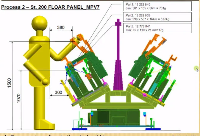
- Ergonomics is the study of. human movement and posture.
- Ergo data will provide information like loading/ unloading height , safety zone for operator to work , etc.
- Ergo data is used when manual operators are required in an assembly operation. So this is important to follow the standard ergo data and every country have their own standard to follow . In this the minimum height , session is given for the operator also minimum distance of operator form the fixture is provided.
- It provides the distance of the safety zone to work around the fixture ie it will give the minimum distance that an operator will have to stay away from the weld gun.
- Minimum height is mentioned in the ergo data because during operation, operator will have to bend for the whole operation that will affect the back of the operator also if the height is more than operator cannot see the ongoing operation properly and his hands will be over his shoulder which will affect his shoulder too.
- So ergo data is provided to make operator a bit comfortable which makes operator more efficient which will reduce the operation time.
7) What do you understand by weld study?
- Weld study is the study of different welding guns and where the welding need to be done on part.
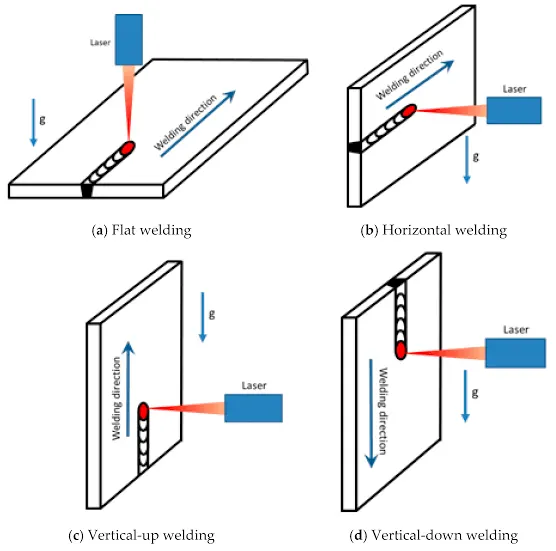
- Weld study includes
- Weld gun details
-
Weld gun is use for welding process, different types of weld guns are available depending upon requirement and also it can be semi automated or automated.
- Weld matrix and weld points
- Weld points are those point in which welding will take place. It provides the exact coordinates for welding to take place.
- Geo weld points and Re-spot weld points
- Weld matrix and weld points are given in the form of spheres on data sheet. The sphere are either green or red in color.
- Geo weld points are red in and the operation will take place in geo station.
- Re-spot weld points are green in color and the welding process will take place in Re-spot stain.
8) What are the criteria for percentage completion in the designing stage? Explain it in detail.
- Percentage completion criteria is actually the schedule of each stages required to complete a particular project within given time period.
- Percentage completion criteria followed in the designing process are
- 0%-25% Input and concept design
- 25%-40% Concept approval and simulation
- 40%-85% Design freezing and detailing
- 85%-100% Check and final dispatched
Input and concept design - 0- 25%
- There is very limited time given for designing the fixture . Exactly 4 days are given for completing 25% of the work.
Concept approval and simulation. 25-40%
- The concept of design will get approval and then the design simulation is also check between 25%- 40%.
Design freezing and detailing. 40%- 85%
- Once the design got the approval the design is freeze or the design got finalize. Once finalize extra details are added which will be necessary and the design is finalize for one last time.
Check and final dispatched. 85%- 100%
- This is the final stage wherein the final quality check is done and then the final dispatch is done to the customer.
9)Brief about "Output" in design.
- Design output in BIW fixture design is giving the part details file to the customer ie 3D, 2D and also the Bill of Material. All small details of the part is submitted to the customer end.
- Unitize tools
- In Unitize tools it requires two drawing sheets ie key sheet and layout sheet. Unitized tools are the fixture tools like the welding fixture, clamp unit, pin unit , rest unit etc and how all these units are placed.
Key sheet- This sheet consists of index of units and. their location in the tool base. So it will give the exact position and the location of the index unit on the tool base.
Layout sheet- It consists of detailed drawing. of individual units to. include all the components.
- Non Unitize tools
- Non utilize tools are those which can stand alone . These tools details are on the layout sheet. The tools are stands, tool changes, etc.
10) What do you understand by structuring a design tree? How does it reduce errors during the design process.
- Design tree is a process in which all the assemblies are given a proper name also the parts or the components that go in that assembly are also name according to a specific standard. This standard differs from customer to customer also the design tree is different.
- Since the standard of design tree differs from one company to another or from one customer to another so they give a template on how to follow their specific standard of structure of design.
- In the design tree a part is given a particular name so to easily identify from which zone it belongs to our from which station or even from assembly or unit.
-By doing this it will avoid any complications during manufacturing and inspection. So structuring a design tree is use to avoid confusion that might arise during manufacturing process or during inspection.
- If the parts are not name properly or the assemblies are not name properly or the structure of design tree is not proper then it will create confusion during manufacturing and leads to error .
- If the parts are name properly then we can easily identify a particular part from which zone or station or assembly or unit it belongs to. It also helps in identifying the quantity of the parts that are being used in the assembly.
11) What are units? Mention 5 types of units.
- U nits are of two types Unitize tools and non Unitize tools.
- A unitized tools are those which are part of the multiple unit or those which have multiple tools inside it. Unitized tools are of two types simple units and complex units.
- Non Unitize tools are unit itself ie they don't have to do any function in process but to keep any component stable like gripper or stand.
1) Simple units
- This unit is very simple in design and the approach of designing and manufacturing it is also very simple like rest unit.
Rest unit
- This unit is normally used for components to rest. There is no upper clamping to it nor any force applied on components. Also there is noscylider. attached to it but it has riser blades and some rest mylers.
Fixed pin unit
- This unit has a pin which is fixed and cannot be moved.
Retract pin unit
- This unit is just opposite to fixed unit ie it can be moved up and down it a certain distance.
Rough locator unit
- This unit is use for loading and unloading of panels.
Sensor unit
- This unit is use for checking a particular panel or components is present or not.
Base unit
- Base unit is where other units will be mounted.
2) Complex units
- The design of such units are very complex like slide unit, etc.
Slide unit
- In these type of units there is inclusion of sliding mechanism
Dump unit
- This unit acts as a storage unit. It consists of conveyor on which the components are dump.
12) Describe fixed pin unit and their purpose?
- Fixed pin unit is a specially design unit use for locating the car panel with the help of pin.
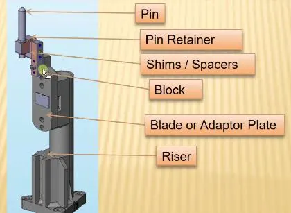
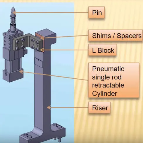
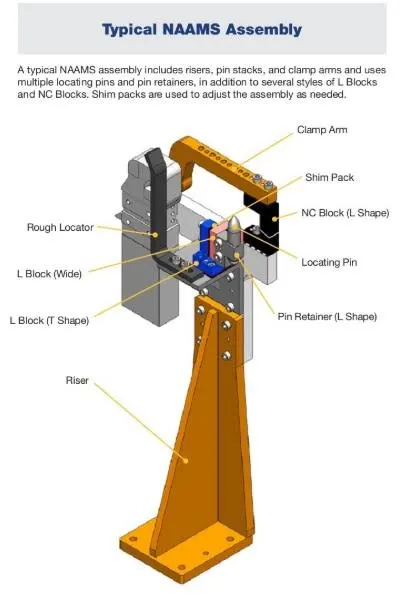
- Fixed pin unit consists of a pin, pin retainer , shims or spacer , bock , blade or adaptor plate and riser .
- Pin is used for locating the panel.
- Here pin retainer is used for holding the pins.
-Shims are used for adjusting the design to manufacturing deviation. Mostly in industries the shims used are very thin or small in size.
- Block is used for the accommodation of shims as per requirement.
- Risers are used to raise or give height to the fixture assembly.
- Retractable pin unit design is located in the car panel with the help of pin such that it will have the same function as that of fixed pin unit. But the retractable unit is mounted on retractable pneumatic cylinder. The pneumatic cylinder is responsible for up and down movement.
13) What are the different parts of fixed unit?
- A fixed unit consists of shims, riser , blocks and sensor unit.
- Shims
- Shims used in fixed unit is small or thin with tapered or wedge shape material. It is generally used to fill small gaps or spaces in between the objects. Shims are used to provide support, to make adjustments for better fit also to provide level surface.
- Riser
- In fixed unit risers are generally used for mounting toggle clamp, rest , location pin and clamp Mylers. There can be more than one risers used in fixed unit mounting clamps , rest and locating pin. Risers are generally made up of plate fabrication or plate and tube welding together or even single gas cut plate.
- Block
- Blocks are versatile such that it can be machined to form any desired fixture components. Since the blocks comes as a blank block there are many possibilities to make fixture components.
- Sensor unit
- Sensor unit is used to sense the car panel by means of electrical signals.
14) What is the purpose of making rest unit & describe its parts?
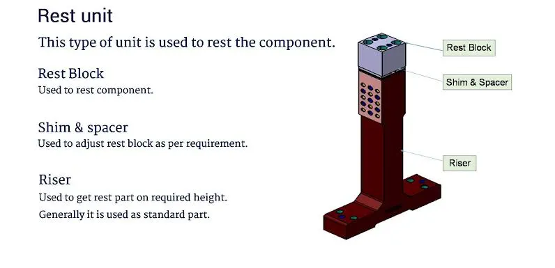
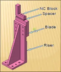
- This unit is used for resting or to support the. car panel . At consists of NC block , shims and risers.
- NC Block
- Blocks are versatile such that it can be machined to form any desired fixture components. Since the blocks comes as a blank block there are many possibilities to make fixture components.
- Shims
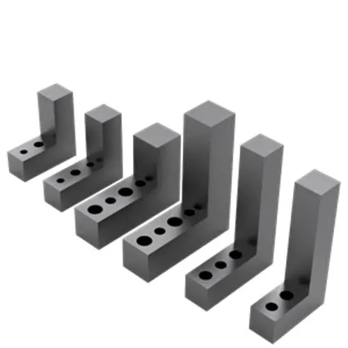
- Shims used in fixed unit is small or thin with tapered or wedge shape material. It is generally used to fill small gaps or spaces in between the objects. Shims are used to provide support, to make adjustments for better fit also to provide level surface.
- Riser
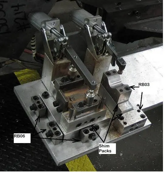
- In fixed unit risers are generally used for mounting toggle clamp, rest , location pin and clamp Mylers. There can be more than one risers used in fixed unit mounting clamps , rest and locating pin. Risers are generally made up of plate fabrication or plate and tube welding together or even single gas cut plate.
15) What are the basic fundamentals to design a sensor unit?
- A sensor unit is used to detect car panel if loaded or not be by using electrical signals . The signals are then sent to PLC( Programmable logic controller) which will decide to execute the next process or not.
Fundamentals of sensor unit
- Before any process to execute first the panel should be sensed by the sensor .
- Each panel which is loaded should be sensed by two or more sensor and its is preferred that the sensor are placed diagonally opposite ends of panels.
- Depending upon the size of the panel the number of sensors are differs.
- If the panel size is small than only one sensor is enough for the panel detection .
- If the panel size is large than two or more sensors are use for the detection.
There are many types of sensors used in fixture operation they are
- Proximity sensor
- Proximity sensors are used to detect the components which are very close as its range is from 5mm to 10mm. This sensor is also use in mobile phones.
- Laser sensor
- Laser sensors are use when the parts to be detected are at far distance such that other sensors cannot detect it.
- Photo electric sensor
- This sensor is used if there is presence or absence of components. It can be used to provide distance of components , it makes use of light transmitter or infrared and . Photoelectric receiver.
16) What is a Rough locator unit and what are the basic fundamentals to consider while designing it?
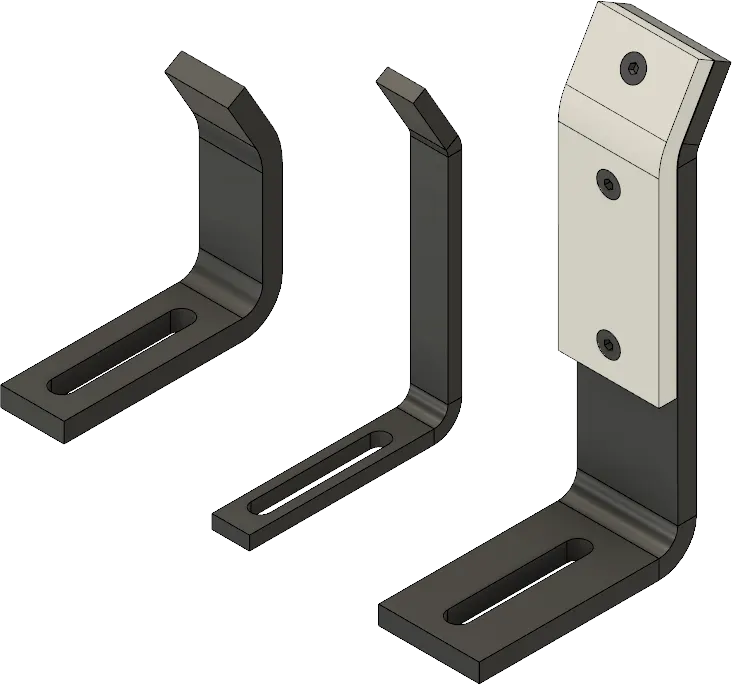
- Rough locators are use for loading and unloading of panels. This is very useful as it helps in loading the parts with proper orientation.
Fundamentals of rough locators
- The rough locators has to be placed at the edge of the car panel or the component which needs to be guided.
- Rough locators are placed such a way that they should not touch the panel or component while loading or unloading otherwise they will get damage.
- Rough locator are placed at an angle where the panel edge. is supposed. to be.
- The panel that is to be loaded has to come from top to bottom and then unloading from reverse direction.
- The rough locators should be design in such a way that it should have two slots that will help in mounting for easy adjustments.
17) What is a Base unit and described its part?
- A base unit is design such a way that all other units can be mounted on it like pin unit , clamp unit , rest unit, rough locators , etc and also some tools like pneumatic valve box , trunking cable pathe , etc are also mounted on base unit.
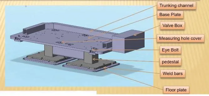
Different parts of the base unit are
- Valve box
- A valve box supplies air to all the pneumatic cylinders on the base unit with the help of solenoid valves in it.
- Measuring hole cover
- It is used for measuring purpose.
- Eye bolt
- It is used to drag the entire unit and relocate .
- Pedestal
- This pedestal is used for standing the entire unit.
18) What is a dump unit and what are its function?
- Dump units is used when there is some limitations to perform some operation in simple units. In this the panel is in open position and we have to able to remove it.
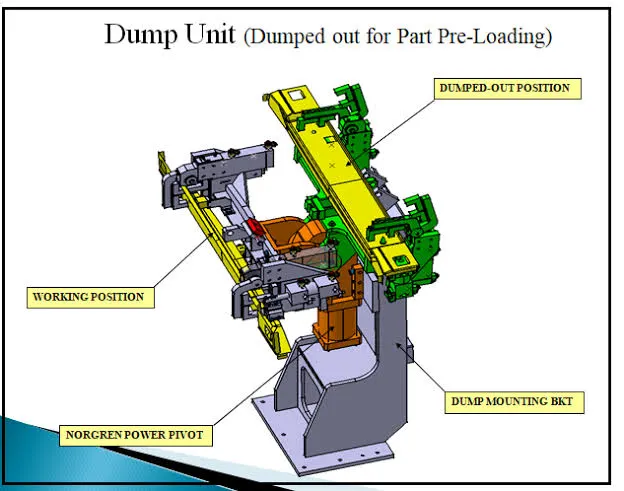
Functions of dump unit
- It ensures that the panel is rested properly while welding operation is being done and also restrict its motion.
- It also ensures that the rotation is restricted of the panel by using pins, side blocks , magnets , etc.
- It also make sure that there is enough clamping force in the cylinders such that it does not move during welding operation.
- Shims in the dump unit should be in correct proportion for the panel adjustments.
19) What is a slide unit? Mention where slide units are commonly used.
- Slide unit is generally used when there is space constraints or when we cannot use any different types of units to design the entire assembly. That's when we use slide unit.
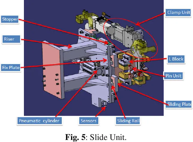
- Slide unit is mostly used where there is less space and places where accessibility is less
- Slide unit is used when there are many small panels closed to each other and there is less space as required for the panels for resting, locating by 2 pins , clamping , sensors , etc. So to overcome from this issue a slide unit is used on which pin uni, clamp unit, rest unit, etc are mounted on it. With the help of guide rails , guide blocks , cylinder , locking mechanisms, stop blocks and sensors it will slide. When a particular panel is to be welded then the slide will move forward starts welding , upon completing the process the slide will move back and gets lock to its positioned.