Week 2 Bevel Gear Challenge
AIM :-Perform a grid dependency test for the Bevel gear simulation for mesh sizes of 6,5 and 4 mm
Grid dependency test :- it is to investigate how the solution depends on the grid size by running the simulation with refined mesh that is finer the mesh, higher is the accuracy of the result but with additional cost on computation time and computational power. Since, solutions are interpolated at the nodes to get an approximate result, higher the number of nodes and elements higher is the computational time and power required to complete the simulation.
So, the grid dependency test helps in determining optimal mesh size where the accurate result could be obtained keeping in the mind the cost of time and power. Since the result obtained are approximate,
Refining mesh further would result in negligible per cent change is the result but only increase the computational cost.
case setup
- import the given cad model into ansys workbench, simplify the geometry which leads to less simulation time and better results at required portion using space claim
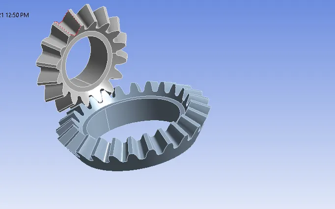
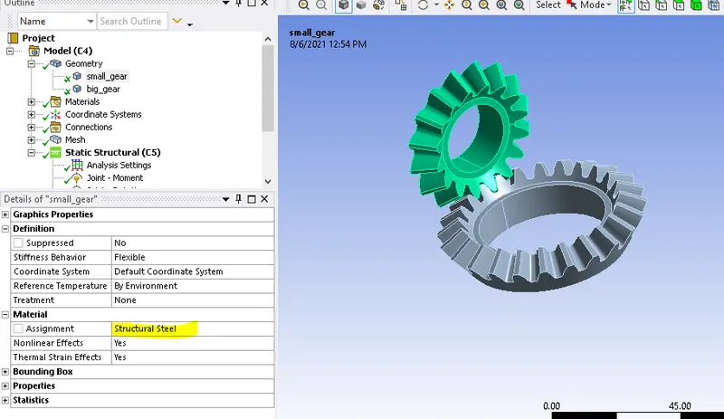
- Rename the components as small_gear & big_gear , assign structural steel as material.
- properties of material
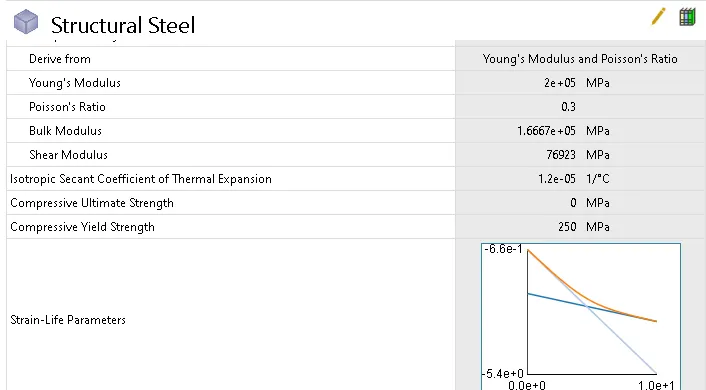
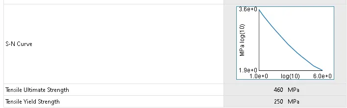
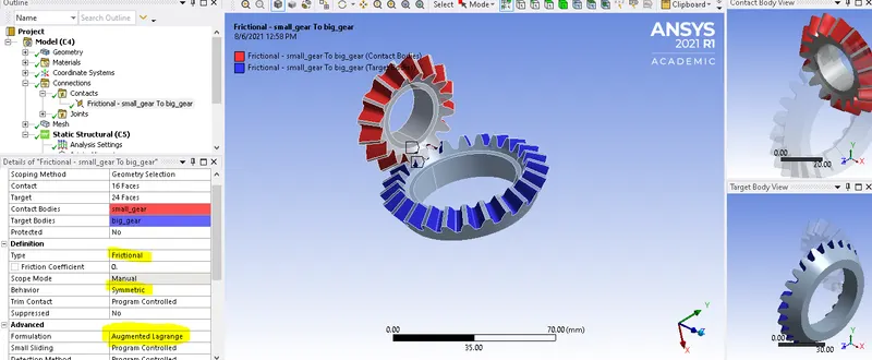
- Contacts - Friction less contacts were setup between two gears. To avoid unnecessary complexity select necessary faces that comes into contact during simulation.
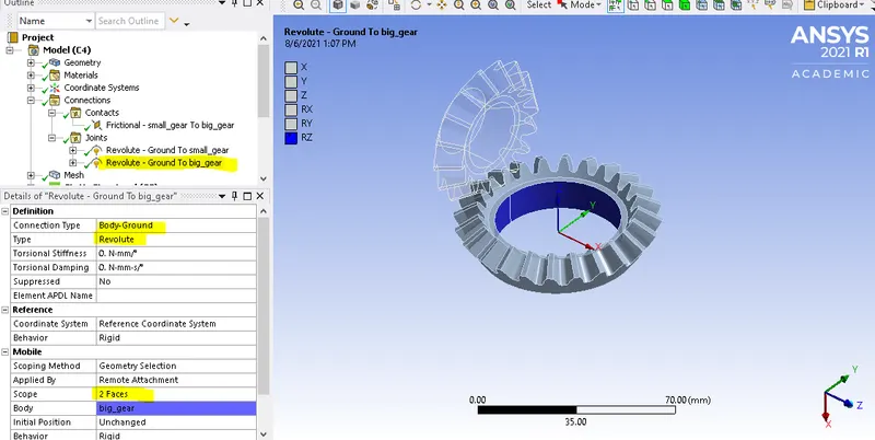
- Joints - Revolute joints are setup between two gears w.r.t. ground.
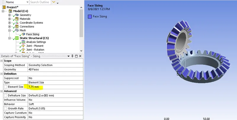
- Mesh - generated mesh for total body of components with an element size of 6mm , but our main focus is on gear tooth surface so to get better results refine thoose surfaces with an element size of 1.75mm using Face sizing option
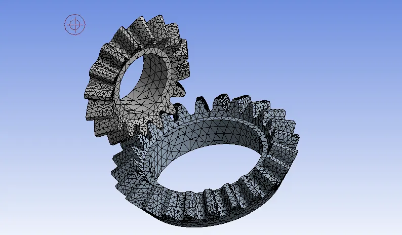
- Analytical settings - this analysis setup for 6 steps, this doesn't control time step, but it is only indication of points where boundary conditions change. the time step is auto controlled by minimum ,initial maximum and time steps.
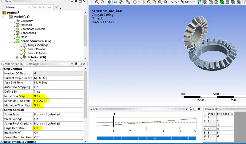
- Boundary conditions
A joint rotation is given to one revoution joint in increment of 20 degree for 6 steps.
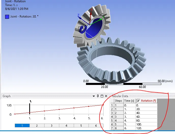
this joint rotates against a moment load (100 N-mm) in the other revolute joint.
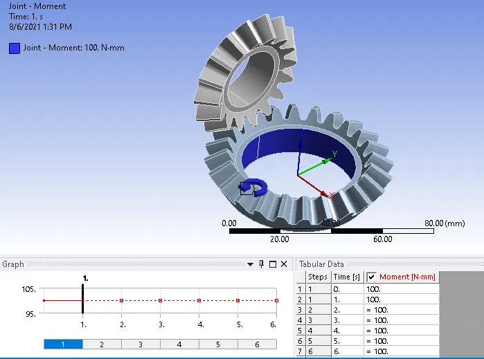
- Follow the same procedure for case -2 with an element size of 5mm and for case -3 with an element size of 4mm.
RESULTS
case 1- element size of 6 mm
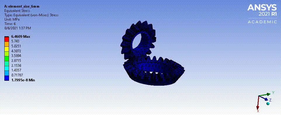
Equivaent stress
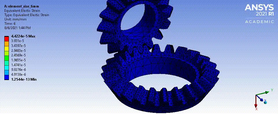
Equalent elastic strain
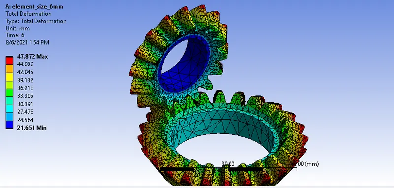
Total deformation
case 2 - element size of 5 mm
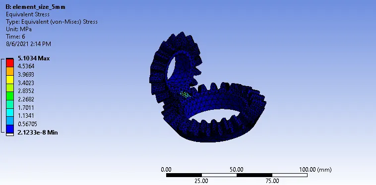
Equivaent stress
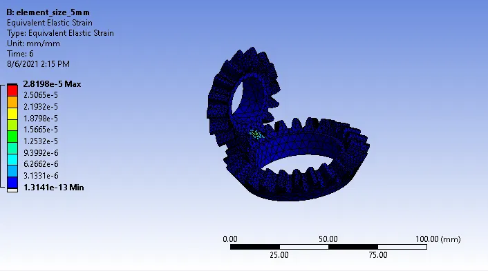
Equalent elastic strain
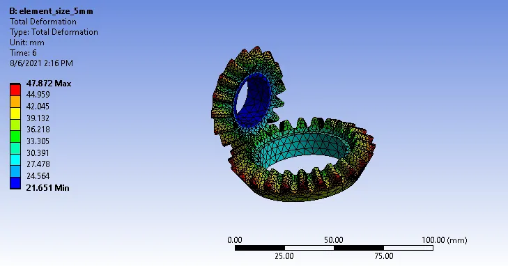
Total deformation
case 3 - element size of 4 mm
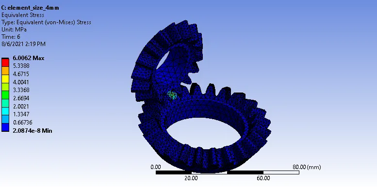
Equivaent stress
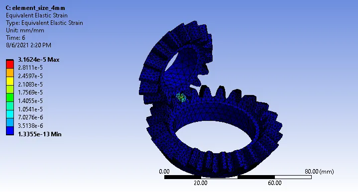
Equalent elastic strain
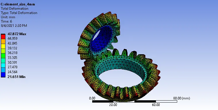
Total deformation
COMPARISION OF 3 CASES RESULTS
| mesh size (6mm) | mesh size (5mm) | mesh size (4mm) | |
| Equivaent stress (MPA) | 5.8607 | 5.104 | 6.0062 |
| Equalent elastic strain | 3.0727e-5 | 2.8198e-5 | 3.1624e-5 |
| Total deformation (mm) | 47.872 | 47.872 | 47.872 |
| no.of. nodes | 41581 | 42595 | 44232 |
| no.of. elements | 25257 | 25858 | 26855 |
| computational time | Low | Medium | High |
CONCLUSION
- Total deformation (47.872) is same all 3 cases , it mans mesh size won't shows effect on total deformation.
- percentage change of Equalent elastic strain is almost similar in all 3 cases
- Equivaent stress value changes with element size reduce in mesh size leads to accurate simulation results.
- Selection of mesh size depends on lot of factors like, computational time, accuracy of result, type of application and so on..
- before selecting the mesh size consider the above mentioned factors.
Google link
https://drive.google.com/file/d/1jMFkbfzbTNg-HNkga57Zg9FpVc_1pP7m/view?usp=sharing