Week 2 Bevel Gear Challenge
AIM: The aim of this week challenge is to perform a grid dependency test on bevel gears for various mesh sizes and explain the result for various stress and strain plots.
PROCEDURE:
GRID DEPENDENCY TEST:
Whenever you are going to find a numerical solution through discretization of a governing differential equation then your solution will be dependent upon number of grid points that are used to arrive at the solution.Generally when you increase the number of grid points the solution will be more accurate but the disadvantage is that it will result in increase of computational cost.So the main aim of this test is to find the appropriate number of grid where on furthur increasing the grid number there will only be a significant change in the end result and the computation time can be controlled based on the appropriate grid size.
step 1: Open the ansys workbench module and select the static structural analysis.
step 2: right click the geomentry tab and select import geomentry --> browse --> select the file --> open.
step 3: Now click on the geomentry tab and select edit geomentry in space claim option
step 4: Now remove the material near the center hole of the gear to optimize the design.
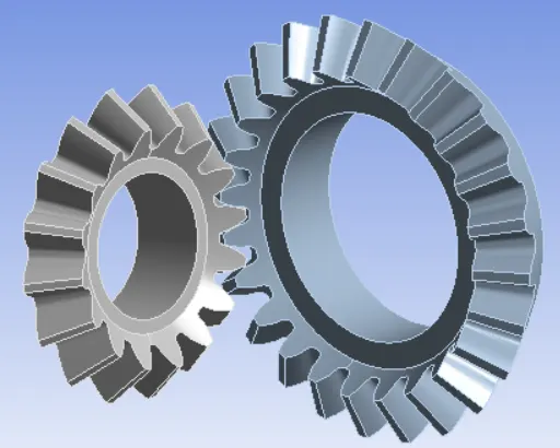
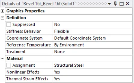
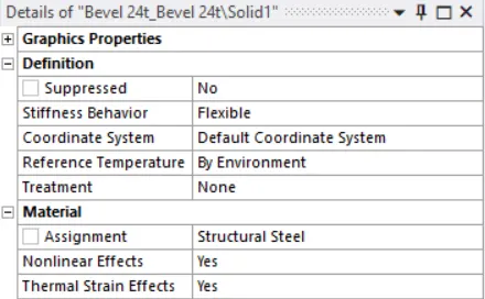
step 5: Now assign the material structural steel to both the gears.
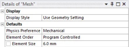
step 6: Now change the mesh size of the element to 6mm and mesh the model.
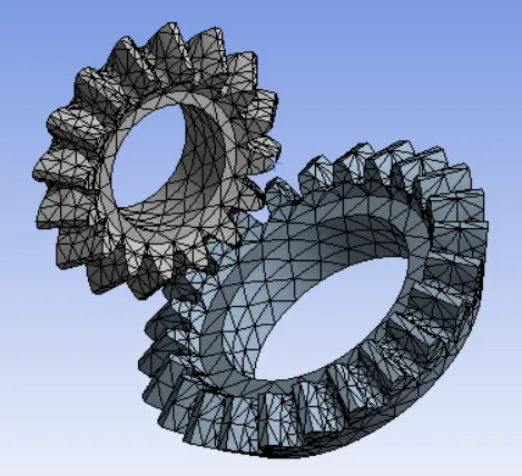
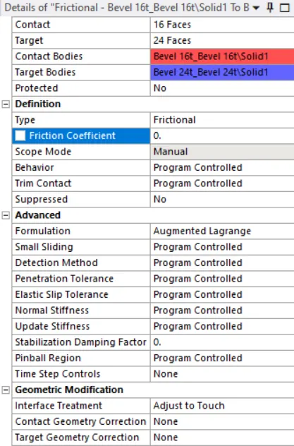
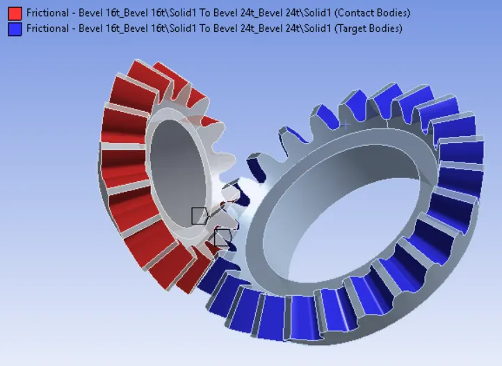
step 7: Now create the contact between two contact.
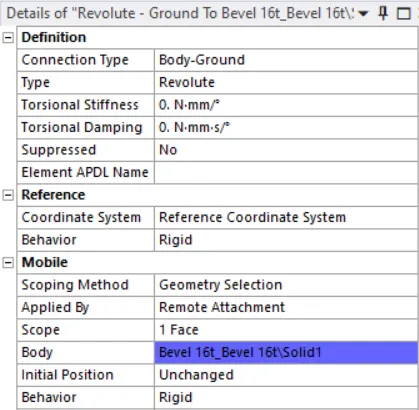
step 8: Now create a revolute joint for both the gears.
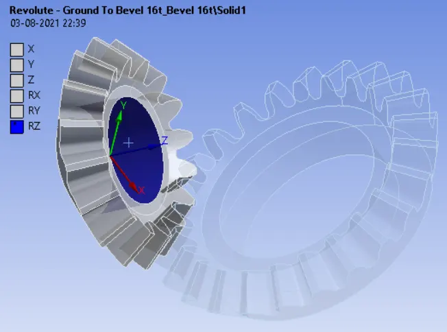
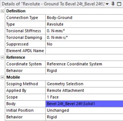
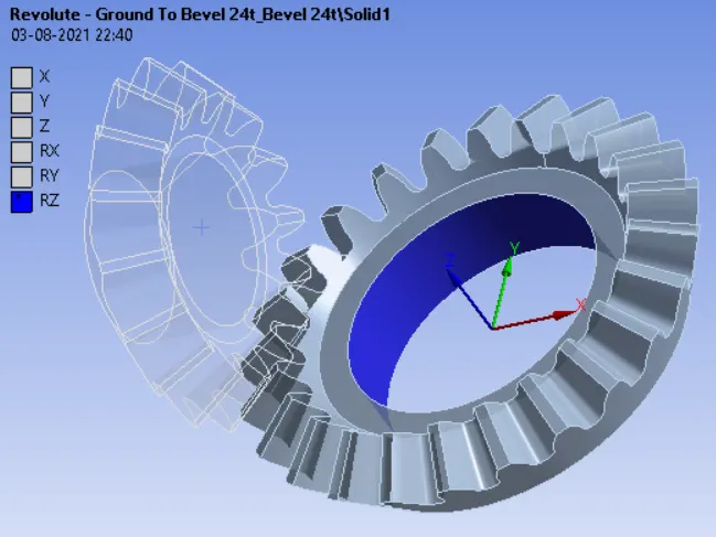
step 9:Now change the analysis settings and ON the large deflection.
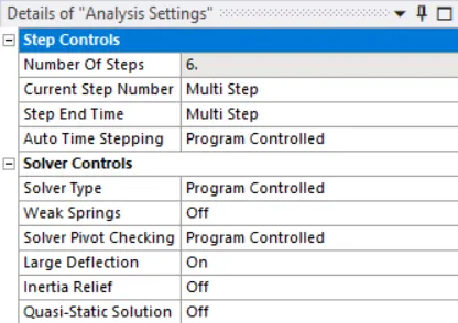
step 12: Now run the simulation.
step 13: Now include the total deformation,Equivalent stress and stress intensity in output files.
Step 14: Now repeat the simulation by changing the mesh size to 5mm and 4mm
Step 15: Compare the result plot and give a detailed explanation.
OUTPUT RESULT:
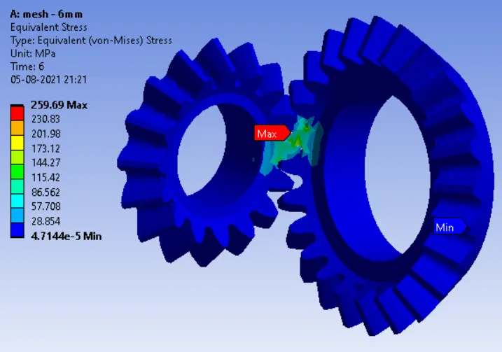
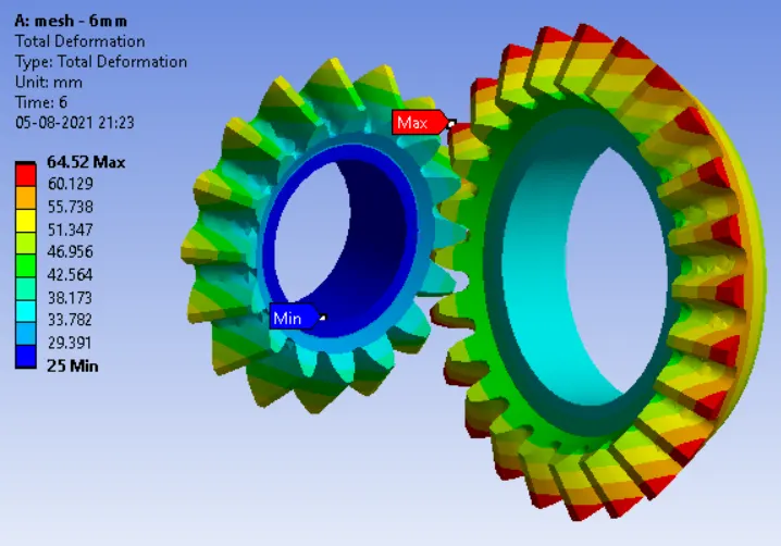
1. 6MM MESH
EQUIVALENT STRESS:
TOTAL DEFORMATION:
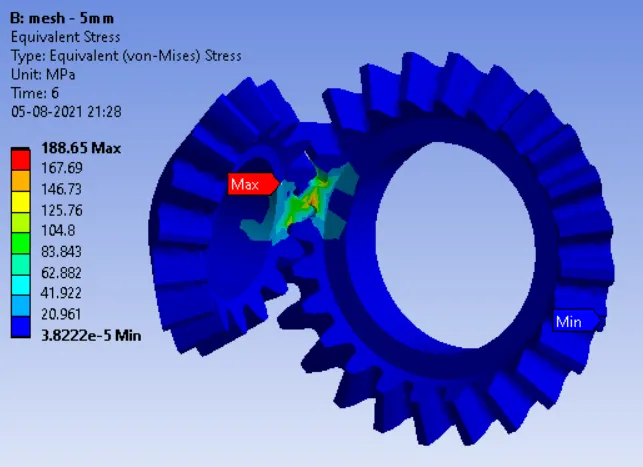
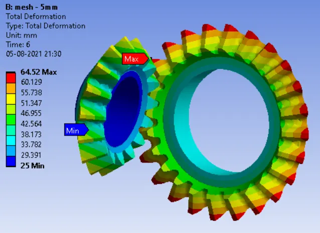
2. 5MM MESH
EQUIVALENT STRESS:
TOTAL DEFORMATION:
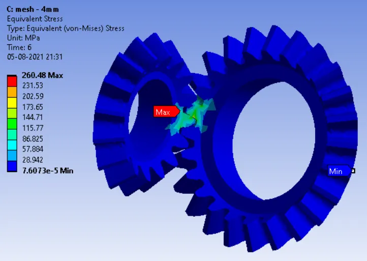
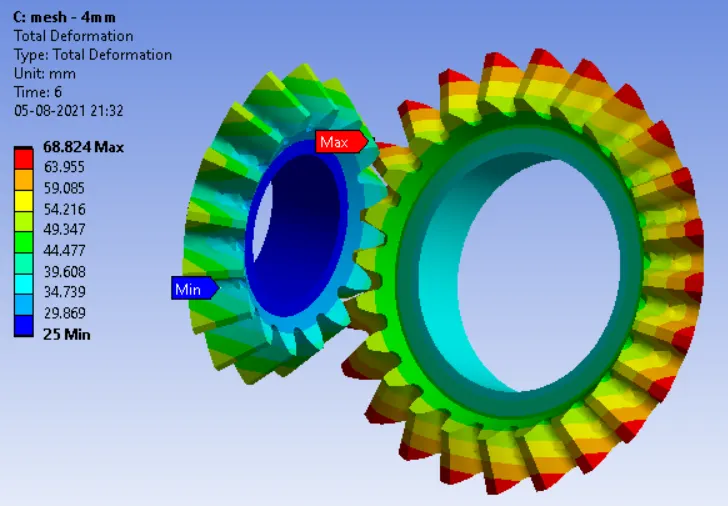
3. 4MM MESH
EQUIVALENT STRESS:
TOTAL DEFORMATION:
CONCLUSION:
| Equivalent Stress in Mpa | Total Deformation in mm | |||
| MIN | MAX | MIN | MAX | |
| 6mm mesh | 4.71E-05 | 256.69 | 25 | 64.52 |
| 5mm mesh | 3.82E-05 | 188.65 | 25 | 64.52 |
| 4mm mesh | 7.60E-05 | 260.48 | 25 | 68.82 |
Based on the result we got from the above simulation, the total deformation is same for 6mm and 5mm mesh and there is a slight increase in 4mm mesh.The equivalent stress for the 6mm and 4mm mesh are almost similar but there is a drastic decrease in the 5mm mesh which may be due to the element formulation at that point.When i tried with 4.8mm the equivalent were about 266 Mpa.From the range of 4.8 to 4.9mm the stress are lowering to 188Mpa.