Week 2 Bevel Gear Challenge
GRID DEPENDENCY TEST ON BEVEL GEAR SIMULATION
AIM :
To perform stress analysis on the bevel gear with grid dependency test of different mesh sizes of 6 mm, 5 mm, 4 mm.
GRID DEPENDENCY TEST:
Generally, analysis is carried out in ansys after the generation of mesh, as the mesh gets finer the results become accurate. In order to get fine results in the Ansys, the, mesh size has to be refined, while doing so, the no .of. Elements and no.of.nodes also increases, which will probably increase the computational time and cost of computation.
To overcome this, we are implementing grid dependency test here, where it will set the mesh size on the workpiece to be analyzed, to a default one on the basis of the geometry, where we can still get the accurate and accepting results, while implementing the grid dependency test here the computational time and cost of the computation decreases. Further refinement of this generated mesh can also provide the accurate results but slightly, which will actually increase the computational time.
So, the purpose of performing grid dependency test is to start with the coarse mesh to provide a solution and then we can refine the mesh to finer or smaller meshes to get the optimum results
PROCEDURE :
- At first open the ansys workbench and then click on the static structural analysis method and rename to bevel gear simulation
- Next we need to upload the material from the engineering data sources to our desired material , here we used structural steel
- Then upload the geometry provided , so in this is case we are particularly focused on the stress and strain analysis or behaviour on the gear tooth , so we are removing the unwanted portion of the gear in the ansys spaceclaim software
- After uploading the geometry , we then need to update the mechanical model , by specifing the connections
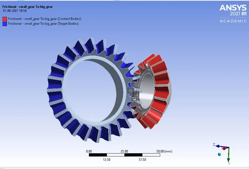
- So in general , the ansys software itself recognizes certain contacts between the bodies , we are mainly focused on all the tooth of the gears , selecting the gear tooth manually and setting up for connection .
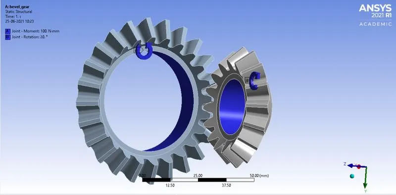
- Then , attach revolute joints between the gears so that it can rotate according to the joint load we are providing with .
- Once after setting up the contacts, we are now setting up the analysis setting where we need to solve the problem by means of time
- We are imposing the tabular values as the input to run the simulation as the basis of time substeps
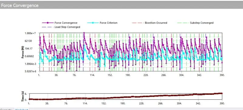
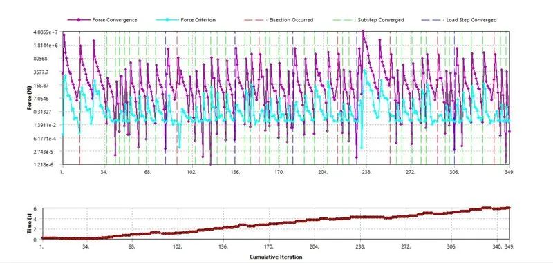
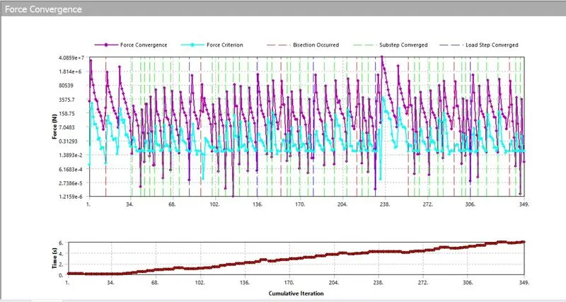
- So the solver will run the simulation and analyse for 6 sec and accordingly to our time steps , to check whether the force convergence and force criterion meets to complete one load cycle , to confirm that the solution is valid
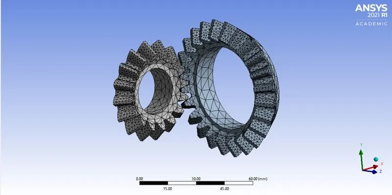
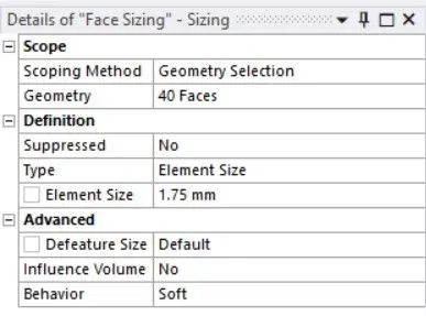
- Now we are creating a mesh of tetrahedral of required sizing ( 6,5,4mm) and the face sizing of 1.75 mm applied on the face of the gear tooth .
- After generating the mesh , we are now creating a joint load on target bodies and contact bodies , target body ( big gear ) is imposed with 100 Nmm moment to run in clockwise direction , and the contact body( small gear ) to rotation of 120 degrees as splitted in to 6 parts of 20 degrees in the anticlockwise direction
- After setting up the analysis settings and mesh sizes , we are now inserting the desired post – processing parameters to solve for , total deformation ,von-misses stress and strain .
GEOMETRY :
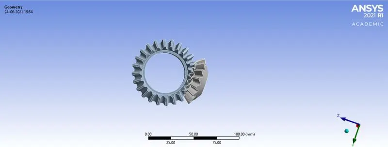
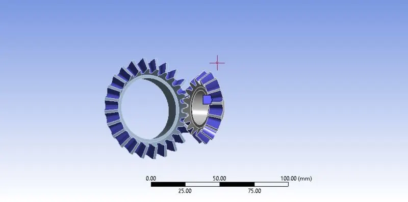
The provided geometry had been modified in spaceclaim accordingly .
CONNECTIONS :
The geometry had been provided with boundary conditions for the analysis by means of contacts and joints
CONTACTS :
As we are very specific in the contacts as the analysis should be carried out on all the tooth , and we have provided the contacts manually to all the gear tooth.
JOINTS :
Joints have been provided to carry out the simulation and loads have to be provided based on the type of support .
MESH :
Analysis has to be carried out after the generation of mesh . in this case we have 3 cases of mesh .
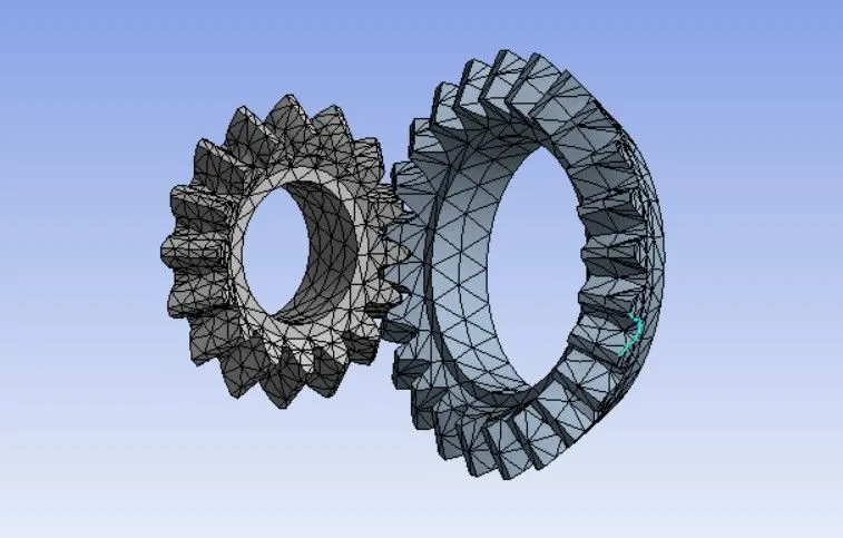
Similarly. we are introducing Face sizing, here we are concentrating mainly on the tooth , so we are setting up the face mesh of a default value mesh of 1.75 mm.
CASE 1 :
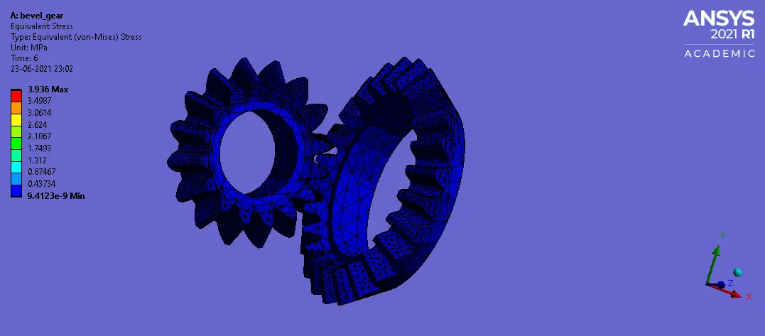
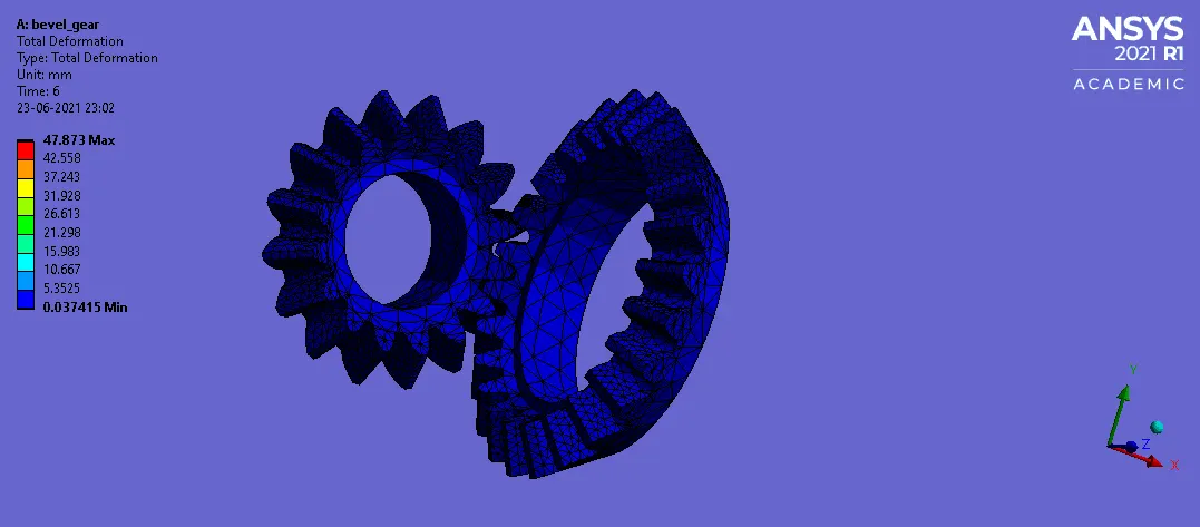
MESH SIZE : 6 mm
MATERIAL USED : structural steel
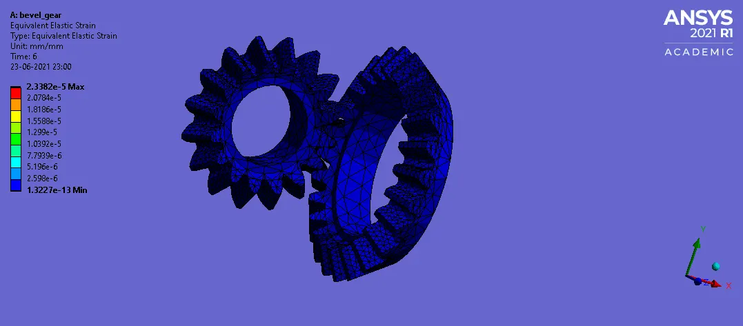
ELASTIC STRAIN ( VON _ MISSES ) :
EQUIVALENT STRESS ( VON - MISSES ) :
TOTAL DEFORORMATION :
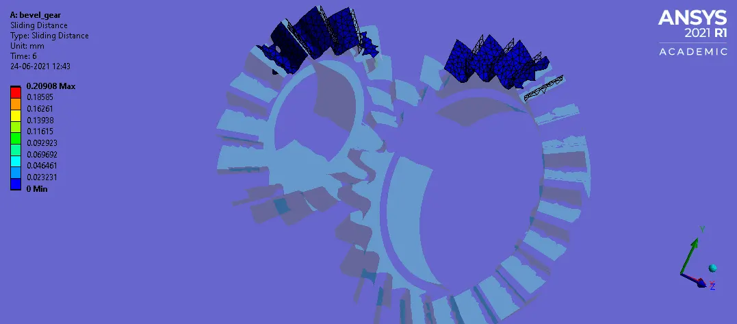
CONTACT SLIDING :
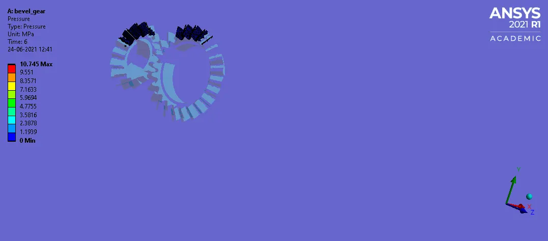
PRESSURE :
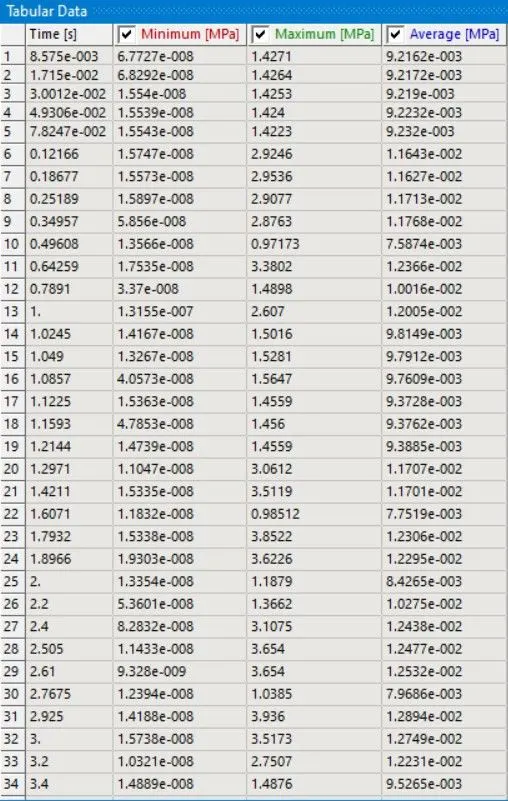
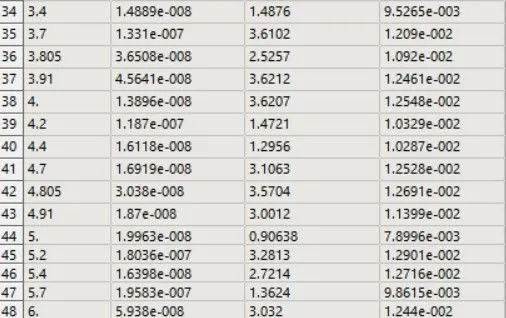
STATISTICS :
EQUIVALENT STRESS :
CONVERGENCE PLOT :
CASE 2 :
MESH SIZE : 5 mm
MATERIAL USED : STRUCTURAL STEEL
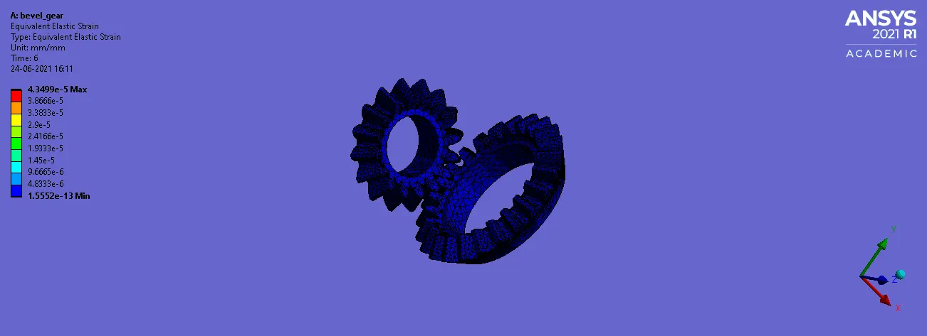
ELASTIC STRAIN ( VON - MISSES ) :
EQUIVALENT STRESS ( VON - MISSES ) :
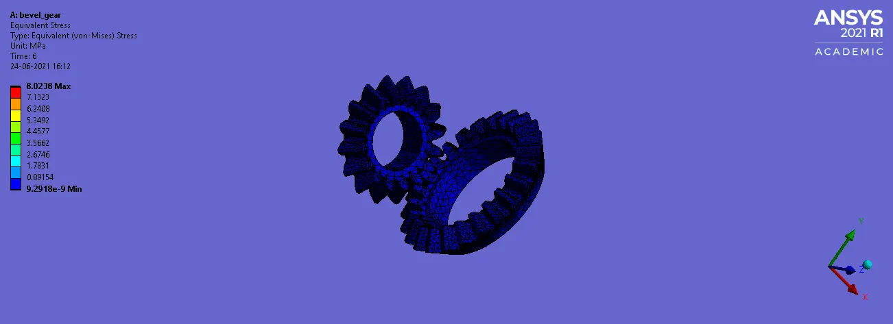
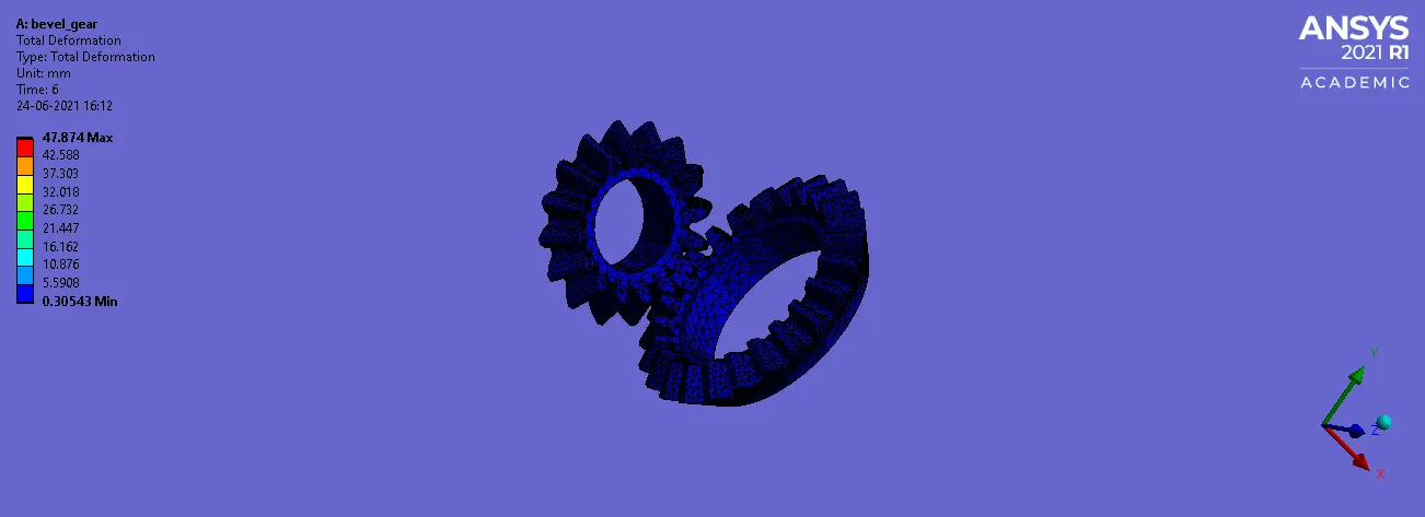
TOTAL DEFORMATION :
FORCE CONVERGENCE PLOT :
CASE 3
MESH SIZE : 4 mm
MATERIAL USED : STRUCTURAL STEEL
ELASTIC STRAIN ( VON -MISSES ) :
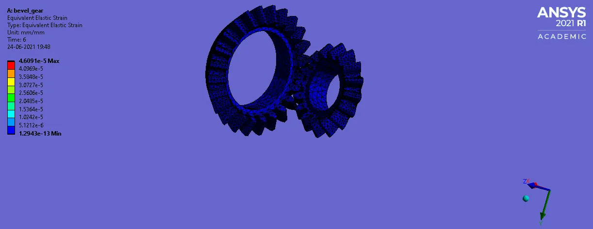
EQUIVALENT STRESS ( VON - MISSES ) :
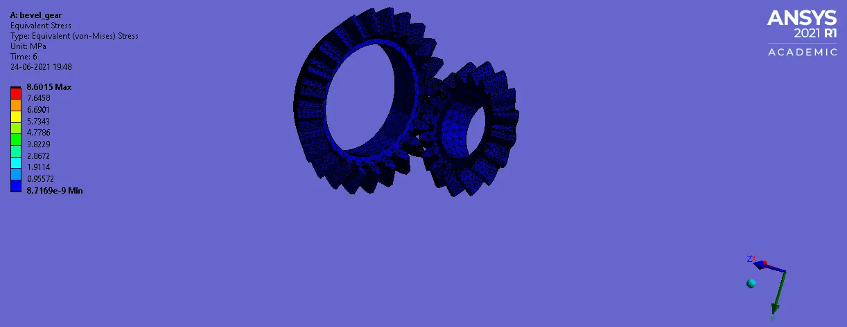
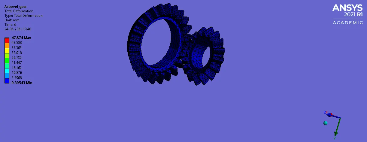
TOTAL DEFORAMTION :
FORCE CONVERGENCE PLOT :
CONCLUSION :
From the above simulations , we come to conclude that , when using grid dependency test for the simulation it shows accurate results on further refinement of the mesh provided accurate results , on this analysis on 6,5,4 mm mesh in the simulation we come to conclude that when using 6 mm mesh , the stress acting on the gear is less than the other two mesh sizes .